Page 86 of 1306

Actual work procedures are explained using a DTC as an example. Be careful so that not only the DTC, but
all of the data listed above, are cleared from the ECM memory during work procedures.
NVIS (Nissan Vehicle Immobilizer System Ð
NATS)
NEEC1601
SEF515Y
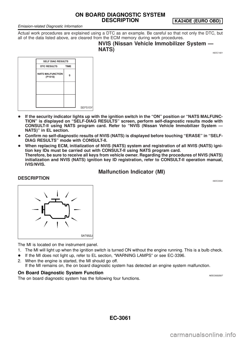
+If the security indicator lights up with the ignition switch in the ªONº position or ªNATS MALFUNC-
TIONº is displayed on ªSELF-DIAG RESULTSº screen, perform self-diagnostic results mode with
CONSULT-II using NATS program card. Refer to ªNVIS (Nissan Vehicle Immobilizer System Ð
NATS)º in EL section.
+Confirm no self-diagnostic results of NVIS (NATS) is displayed before touching ªERASEº in ªSELF-
DIAG RESULTSº mode with CONSULT-II.
+When replacing ECM, initialization of NVIS (NATS) system and registration of all NVIS (NATS) igni-
tion key IDs must be carried out with CONSULT-II using NATS program card.
Therefore, be sure to receive all keys from vehicle owner. Regarding the procedures of NVIS (NATS)
initialization and NVIS (NATS) ignition key ID registration, refer to CONSULT-II operation manual,
IVIS/NVIS.
Malfunction Indicator (MI)
DESCRIPTIONNEEC0032
SAT652J
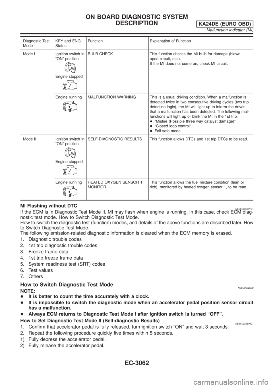
The MI is located on the instrument panel.
1. The MI will light up when the ignition switch is turned ON without the engine running. This is a bulb check.
+If the MI does not light up, refer to EL section, ªWARNING LAMPSº or see EC-3396.
2. When the engine is started, the MI should go off.
If the MI remains on, the on board diagnostic system has detected an engine system malfunction.
On Board Diagnostic System FunctionNEEC0032S07The on board diagnostic system has the following four functions.
ON BOARD DIAGNOSTIC SYSTEM
DESCRIPTION
KA24DE (EURO OBD)
Emission-related Diagnostic Information
EC-3061
Page 87 of 1306

Diagnostic Test
ModeKEY and ENG.
StatusFunction Explanation of Function
Mode I Ignition switch in
ªONº position
Engine stopped
BULB CHECK This function checks the MI bulb for damage (blown,
open circuit, etc.).
If the MI does not come on, check MI circuit.
Engine running
MALFUNCTION WARNING This is a usual driving condition. When a malfunction is
detected twice in two consecutive driving cycles (two trip
detection logic), the MI will light up to inform the driver
that a malfunction has been detected. The following mal-
functions will light up or blink the MI in the 1st trip.
+ªMisfire (Possible three way catalyst damage)º
+ªClosed loop controlº
+Fail-safe mode
Mode II Ignition switch in
ªONº position
Engine stopped
SELF-DIAGNOSTIC RESULTS This function allows DTCs and 1st trip DTCs to be read.
Engine running
HEATED OXYGEN SENSOR 1
MONITORThis function allows the fuel mixture condition (lean or
rich), monitored by heated oxygen sensor 1, to be read.
MI Flashing without DTCNEEC0032S0701If the ECM is in Diagnostic Test Mode II, MI may flash when engine is running. In this case, check ECM diag-
nostic test mode. How to Switch Diagnostic Test Mode.
How to switch the diagnostic test (function) modes, and details of the above functions are described later. How
to Switch Diagnostic Test Mode.
The following emission-related diagnostic information is cleared when the ECM memory is erased.
1. Diagnostic trouble codes
2. 1st trip diagnostic trouble codes
3. Freeze frame data
4. 1st trip freeze frame data
5. System readiness test (SRT) codes
6. Test values
7. Others
How to Switch Diagnostic Test ModeNEEC0032S08NOTE:
+It is better to count the time accurately with a clock.
+It is impossible to switch the diagnostic mode when an accelerator pedal position sensor circuit
has a malfunction.
+Always ECM returns to Diagnostic Test Mode I after ignition switch is turned ªOFFº.
How to Set Diagnostic Test Mode II (Self-diagnostic Results)
NEEC0032S08011. Confirm that accelerator pedal is fully released, turn ignition switch ªONº and wait 3 seconds.
2. Repeat the following procedure quickly five times within 5 seconds.
1) Fully depress the accelerator pedal.
2) Fully release the accelerator pedal.
ON BOARD DIAGNOSTIC SYSTEM
DESCRIPTION
KA24DE (EURO OBD)
Malfunction Indicator (MI)
EC-3062
Page 334 of 1306
Diagnostic ProcedureNEEC0298
1 INSPECTION START
With CONSULT-II
1. Turn ignition switch ON.
2. Select ªSELF DIAG RESULTSº mode with CONSULT-II.
3. Touch ªERASEº.
4. Perform ªDTC Confirmation Procedureº.
See previous page.
5. Is the 1st trip DTC P0605 displayed again?
With GST
1. Turn ignition switch ON.
2. Select MODE 4 with GST.
3. Touch ªERASEº.
4. Perform ªDTC Confirmation Procedureº.
See previous page.
5. Is the 1st trip DTC P0605 displayed again?
YesorNo
Ye s©GO TO 2.
No©INSPECTION END
2 REPLACE ECM
1. Replace ECM.
2. Perform initialization of NATS system and registration of all NATS ignition key IDs. Refer to EC-3231, ªNVIS (Nissan
Vehicle Immobilizer System Ð NATSº.
©INSPECTION END
DTC P0605 ECMKA24DE (EURO OBD)
Diagnostic Procedure
EC-3309
Page 454 of 1306

+Erasing the emission-related diagnostic information using CONSULT-II is easier and quicker than
switching the diagnostic test mode using the data link connector.
NATS (Nissan Anti-Theft System)
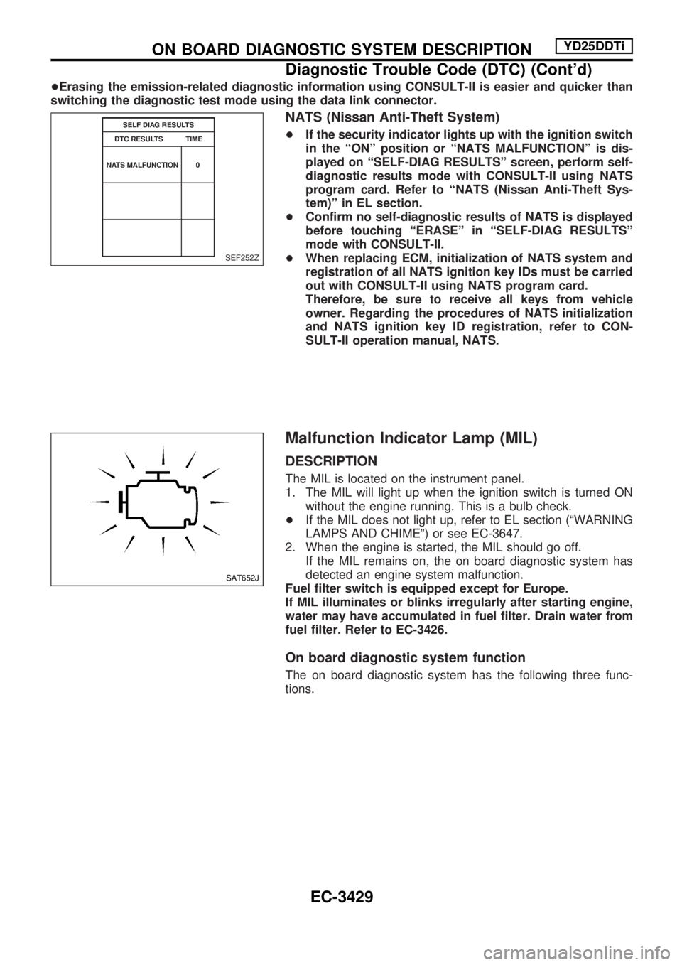
+If the security indicator lights up with the ignition switch
in the ªONº position or ªNATS MALFUNCTIONº is dis-
played on ªSELF-DIAG RESULTSº screen, perform self-
diagnostic results mode with CONSULT-II using NATS
program card. Refer to ªNATS (Nissan Anti-Theft Sys-
tem)º in EL section.
+Confirm no self-diagnostic results of NATS is displayed
before touching ªERASEº in ªSELF-DIAG RESULTSº
mode with CONSULT-II.
+When replacing ECM, initialization of NATS system and
registration of all NATS ignition key IDs must be carried
out with CONSULT-II using NATS program card.
Therefore, be sure to receive all keys from vehicle
owner. Regarding the procedures of NATS initialization
and NATS ignition key ID registration, refer to CON-
SULT-II operation manual, NATS.
Malfunction Indicator Lamp (MIL)
DESCRIPTION
The MIL is located on the instrument panel.
1. The MIL will light up when the ignition switch is turned ON
without the engine running. This is a bulb check.
+If the MIL does not light up, refer to EL section (ªWARNING
LAMPS AND CHIMEº) or see EC-3647.
2. When the engine is started, the MIL should go off.
If the MIL remains on, the on board diagnostic system has
detected an engine system malfunction.
Fuel filter switch is equipped except for Europe.
If MIL illuminates or blinks irregularly after starting engine,
water may have accumulated in fuel filter. Drain water from
fuel filter. Refer to EC-3426.
On board diagnostic system function
The on board diagnostic system has the following three func-
tions.
SEF252Z
SAT652J
ON BOARD DIAGNOSTIC SYSTEM DESCRIPTIONYD25DDTi
Diagnostic Trouble Code (DTC) (Cont'd)
EC-3429
Page 455 of 1306
Diagnostic Test Mode KEY and ENG. Status Function Explanation of Function
Mode I Ignition switch in ON
position
Engine stopped
BULB CHECK This function checks the MIL bulb for dam-
age (blown, open circuit, etc.).
If the MIL does not come on, check MIL cir-
cuit. (See EC-3647.)
Engine running
MALFUNCTION
WARNINGThis is a usual driving condition. When ECM
detects a malfunction, the MIL will light up to
inform the driver that a malfunction has been
detected.
Mode II Ignition switch in ON
position
Engine stopped
SELF-DIAGNOSTIC RESULTS This function allows DTCs to be read.
ON BOARD DIAGNOSTIC SYSTEM DESCRIPTIONYD25DDTi
Malfunction Indicator Lamp (MIL) (Cont'd)
EC-3430
Page 527 of 1306
Diagnostic Procedure
1 INSPECTION START
With CONSULT-II
1. Turn ignition switch ªONº.
2. Select ªSELF DIAG RESULTSº mode with CONSULT-II.
3. Touch ªERASEº.
4. Perform ªDTC Confirmation Procedureº, EC-3501, again.
5. Is the malfunction displayed again?
Without CONSULT-II
1. Turn ignition switch ªONº.
2. Erase the Diagnostic Test Mode II (Self-diagnostic results) memory.
3. Perform ªDTC Confirmation Procedureº, EC-3501, again.
4. Perform ªDiagnostic Test Mode II (Self-diagnostic results)º.
5. Is the DTC 0301 or 0901 displayed again?
Yes or No
YescGO TO 2.
NocINSPECTION END
2 REPLACE ECM
1. Replace ECM.
2. Perform initialization of NATS system and resistration of all NATS ignition key IDs. Refer to EC-3429. (Models with NATS)
3. Perform ªAccelerator Position Sensor Idle Position Learningº of ªBASIC SERVICE PROCEDUREº. Refer to EC-3427.
cINSPECTION END
DTC 0301 ECM 2, DTC 901 ECM 12YD25DDTi
EC-3502
Page 607 of 1306
Diagnostic Procedure
1 INSPECTION START
With CONSULT-II
1. Turn ignition switch ªONº.
2. Select ªSELF DIAG RESULTSº mode with CONSULT-II.
3. Touch ªERASEº.
4. Perform ªDTC Confirmation Procedureº, EC-3581, again.
5. Is the malfunction displayed again?
Without CONSULT-II
1. Turn ignition switch ªONº.
2. Erase the Diagnostic Test Mode II (Self-diagnostic results) memory.
3. Perform ªDTC Confirmation Procedureº, EC-3581, again.
4. Perform ªDiagnostic Test Mode II (Self-diagnostic results)º.
5. Is the DTC 0802 displayed again?
Yes or No
YescGO TO 2.
NocINSPECTION END
2 REPLACE ECM
1. Replace ECM.
2. Perform initialization of NATS system and registration of all NATS ignition key IDs. Refer to EC-3429. (Models with NATS)
3. Perform ªAccelerator Position Sensor Idle Position Learningº of ªBASIC SERVICE PROCEDUREº. Refer to EC-3427.
cINSPECTION END
DTC 0802 ECM 10YD25DDTi
EC-3582
Page 609 of 1306
Diagnostic Procedure
1 INSPECTION START
With CONSULT-II
1. Turn ignition switch ªONº.
2. Select ªSELF DIAG RESULTSº mode with CONSULT-II.
3. Touch ªERASEº.
4. Perform ªDTC Confirmation Procedureº, EC-3583, again.
5. Is the malfunction displayed again?
Without CONSULT-II
1. Turn ignition switch ªONº.
2. Erase the Diagnostic Test Mode II (Self-diagnostic results) memory.
3. Perform ªDTC Confirmation Procedureº, EC-3583, again.
4. Perform ªDiagnostic Test Mode II (Self-diagnostic results)º.
5. Is the DTC 0802 displayed again?
Yes or No
YescGO TO 2.
NocINSPECTION END
2 REPLACE ECM
1. Replace ECM.
2. Perform initialization of NATS system and registration of all NATS ignition key IDs. Refer to EC-3429. (Models with NATS)
3. Perform ªAccelerator Position Sensor Idle Position Learningº of ªBASIC SERVICE PROCEDUREº. Refer to EC-3427.
cINSPECTION END
DTC 0804 ECM 11YD25DDTi
EC-3584