2001 NISSAN PICK-UP fuel cap
[x] Cancel search: fuel capPage 41 of 1306
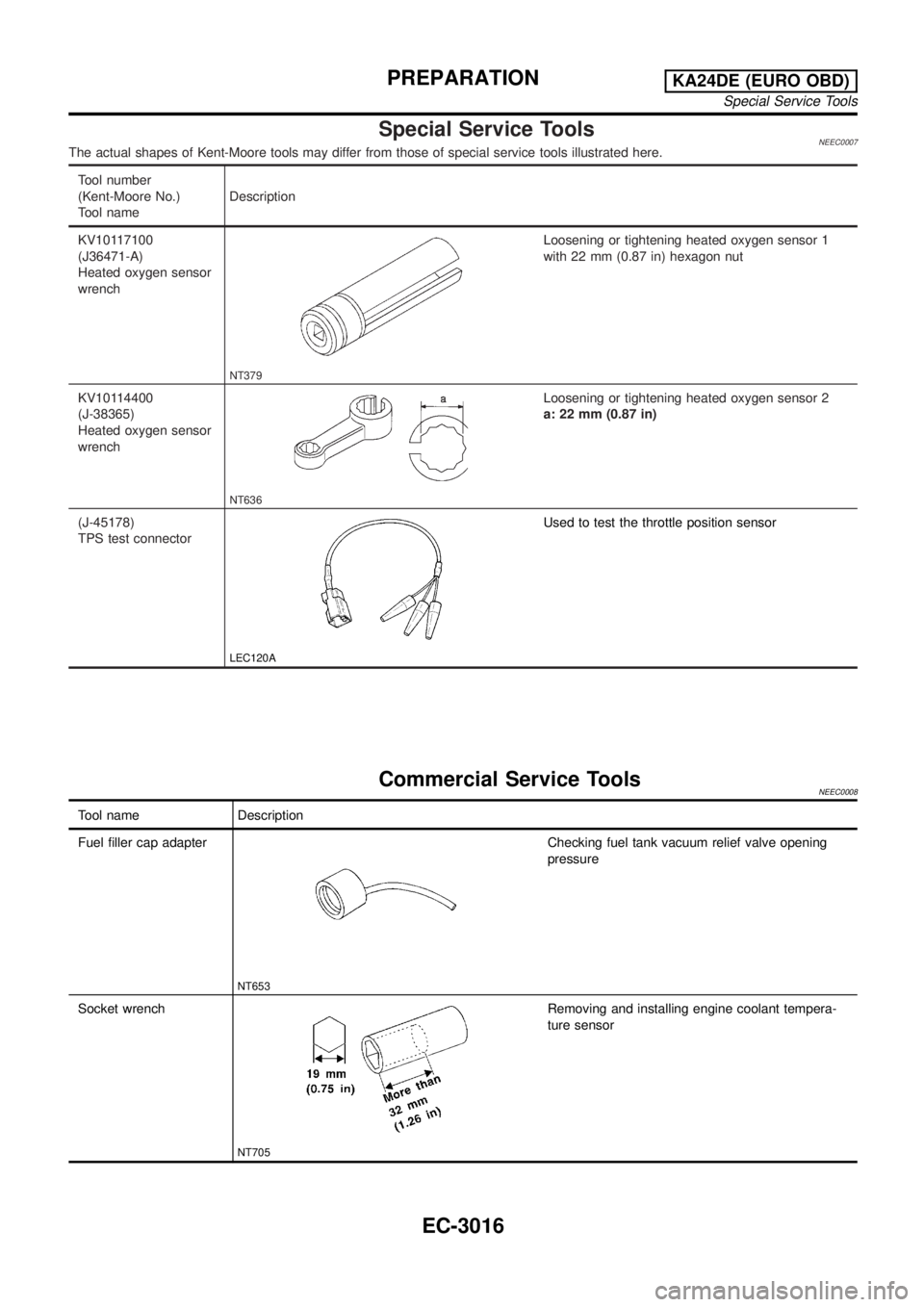
Special Service ToolsNEEC0007The actual shapes of Kent-Moore tools may differ from those of special service tools illustrated here.
Tool number
(Kent-Moore No.)
Tool nameDescription
KV10117100
(J36471-A)
Heated oxygen sensor
wrench
NT379
Loosening or tightening heated oxygen sensor 1
with 22 mm (0.87 in) hexagon nut
KV10114400
(J-38365)
Heated oxygen sensor
wrench
NT636
Loosening or tightening heated oxygen sensor 2
a: 22 mm (0.87 in)
(J-45178)
TPS test connector
LEC120A
Used to test the throttle position sensor
Commercial Service ToolsNEEC0008
Tool name Description
Fuel filler cap adapter
NT653
Checking fuel tank vacuum relief valve opening
pressure
Socket wrench
NT705
Removing and installing engine coolant tempera-
ture sensor
PREPARATIONKA24DE (EURO OBD)
Special Service Tools
EC-3016
Page 55 of 1306
SEF427N
SEF943S
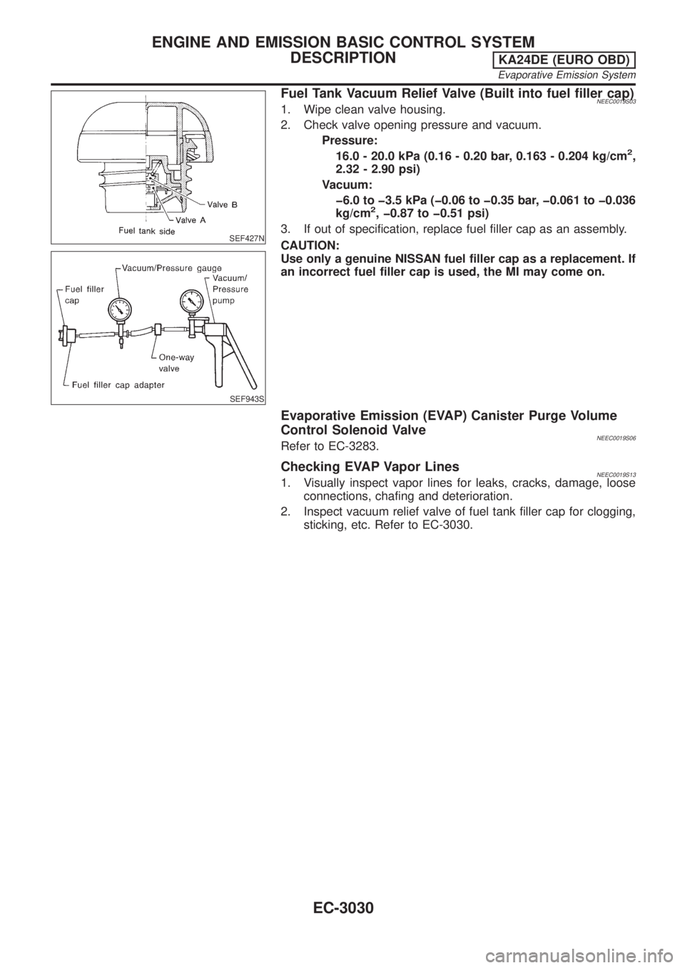
Fuel Tank Vacuum Relief Valve (Built into fuel filler cap)NEEC0019S031. Wipe clean valve housing.
2. Check valve opening pressure and vacuum.
Pressure:
16.0 - 20.0 kPa (0.16 - 0.20 bar, 0.163 - 0.204 kg/cm
2,
2.32 - 2.90 psi)
Vacuum:
þ6.0 to þ3.5 kPa (þ0.06 to þ0.35 bar, þ0.061 to þ0.036
kg/cm
2, þ0.87 to þ0.51 psi)
3. If out of specification, replace fuel filler cap as an assembly.
CAUTION:
Use only a genuine NISSAN fuel filler cap as a replacement. If
an incorrect fuel filler cap is used, the MI may come on.
Evaporative Emission (EVAP) Canister Purge Volume
Control Solenoid Valve
NEEC0019S06Refer to EC-3283.
Checking EVAP Vapor LinesNEEC0019S131. Visually inspect vapor lines for leaks, cracks, damage, loose
connections, chafing and deterioration.
2. Inspect vacuum relief valve of fuel tank filler cap for clogging,
sticking, etc. Refer to EC-3030.
ENGINE AND EMISSION BASIC CONTROL SYSTEM
DESCRIPTION
KA24DE (EURO OBD)
Evaporative Emission System
EC-3030
Page 59 of 1306
If results are unsatisfactory, perform Fuel Pressure Regulator
Check, EC-3034.
SEF718B
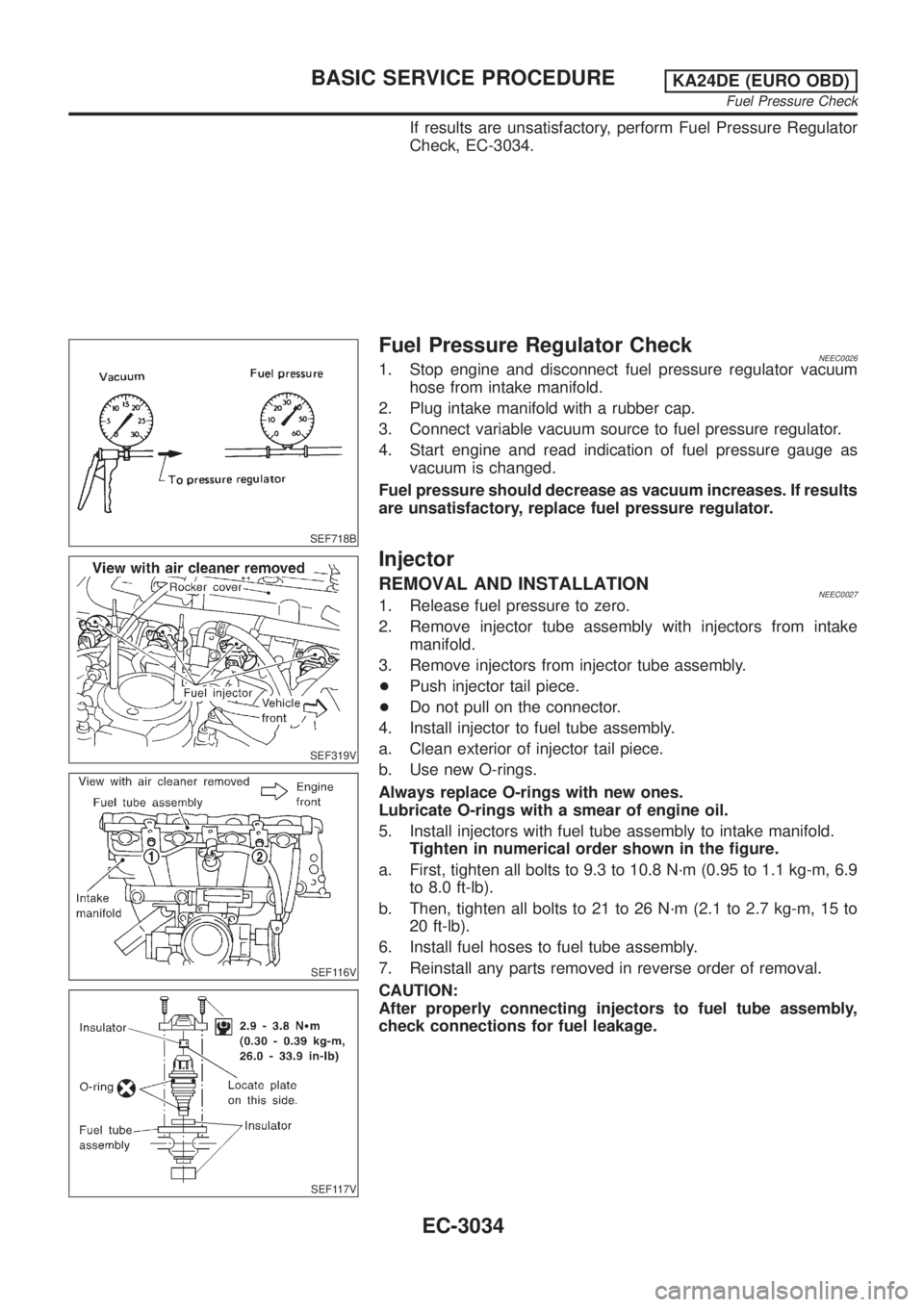
Fuel Pressure Regulator CheckNEEC00261. Stop engine and disconnect fuel pressure regulator vacuum
hose from intake manifold.
2. Plug intake manifold with a rubber cap.
3. Connect variable vacuum source to fuel pressure regulator.
4. Start engine and read indication of fuel pressure gauge as
vacuum is changed.
Fuel pressure should decrease as vacuum increases. If results
are unsatisfactory, replace fuel pressure regulator.
SEF319V
SEF116V
SEF117V
Injector
REMOVAL AND INSTALLATIONNEEC00271. Release fuel pressure to zero.
2. Remove injector tube assembly with injectors from intake
manifold.
3. Remove injectors from injector tube assembly.
+Push injector tail piece.
+Do not pull on the connector.
4. Install injector to fuel tube assembly.
a. Clean exterior of injector tail piece.
b. Use new O-rings.
Always replace O-rings with new ones.
Lubricate O-rings with a smear of engine oil.
5. Install injectors with fuel tube assembly to intake manifold.
Tighten in numerical order shown in the figure.
a. First, tighten all bolts to 9.3 to 10.8 N´m (0.95 to 1.1 kg-m, 6.9
to 8.0 ft-lb).
b. Then, tighten all bolts to 21 to 26 N´m (2.1 to 2.7 kg-m, 15 to
20 ft-lb).
6. Install fuel hoses to fuel tube assembly.
7. Reinstall any parts removed in reverse order of removal.
CAUTION:
After properly connecting injectors to fuel tube assembly,
check connections for fuel leakage.
BASIC SERVICE PROCEDUREKA24DE (EURO OBD)
Fuel Pressure Check
EC-3034
Page 60 of 1306

SEF500V
Fast Idle Cam (FIC)
COMPONENT DESCRIPTIONNEEC0502The FIC is installed on the throttle body to maintain adequate
engine speed while the engine is cold. It is operated by a volumet-
ric change in wax located inside the thermo-element. The thermo-
element is operated by engine coolant temperature.
For inspection refer to ªTROUBLE DIAGNOSIS-BASIC
INSPECTIONº, ªBasic Inspectionº, EC-3086.
Idle Speed/Ignition Timing/Idle Mixture Ratio
Adjustment
NEEC0028PREPARATIONNEEC0028S05+Make sure that the following parts are in good order.
a)Battery
b)Ignition system
c)Engine oil and coolant levels
d)Fuses
e)ECM harness connector
f)Vacuum hoses
g)Air intake system
(Oil filler cap, oil level gauge, etc.)
h)Fuel pressure
i)Engine compression
j)Throttle valve
k)EVAP system
+On models equipped with air conditioner, checks should be carried out while the air conditioner is
ªOFFº.
+When measuring ªCOº percentage, insert probe more than 40 cm (15.7 in) into tail pipe.
+Turn off headlamps, heater blower.
+Keep front wheels pointed straight ahead.
BASIC SERVICE PROCEDUREKA24DE (EURO OBD)
Fast Idle Cam (FIC)
EC-3035
Page 107 of 1306
MEF036D
IntroductionNEEC0036
SEF233G
SEF234G
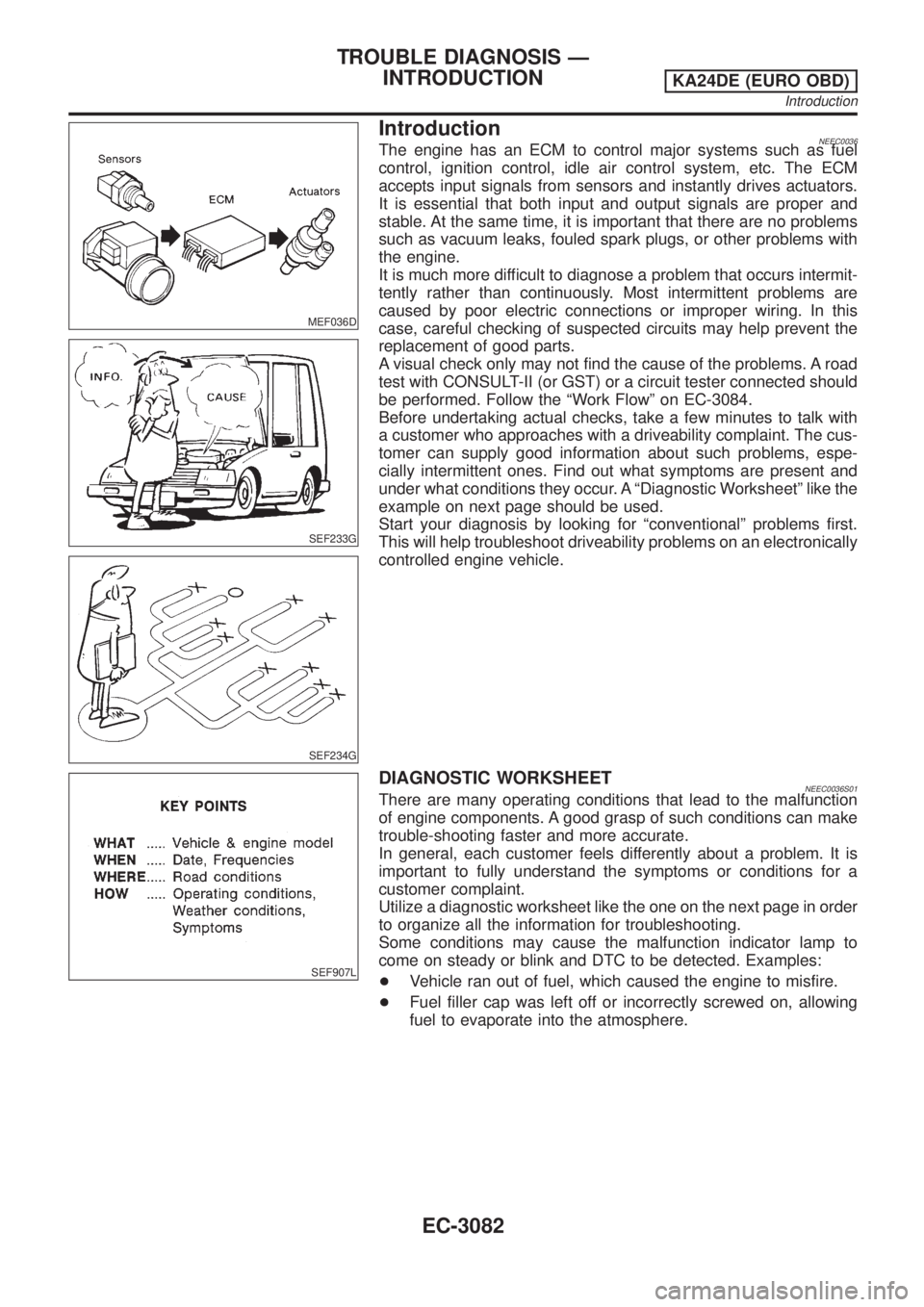
The engine has an ECM to control major systems such as fuel
control, ignition control, idle air control system, etc. The ECM
accepts input signals from sensors and instantly drives actuators.
It is essential that both input and output signals are proper and
stable. At the same time, it is important that there are no problems
such as vacuum leaks, fouled spark plugs, or other problems with
the engine.
It is much more difficult to diagnose a problem that occurs intermit-
tently rather than continuously. Most intermittent problems are
caused by poor electric connections or improper wiring. In this
case, careful checking of suspected circuits may help prevent the
replacement of good parts.
A visual check only may not find the cause of the problems. A road
test with CONSULT-II (or GST) or a circuit tester connected should
be performed. Follow the ªWork Flowº on EC-3084.
Before undertaking actual checks, take a few minutes to talk with
a customer who approaches with a driveability complaint. The cus-
tomer can supply good information about such problems, espe-
cially intermittent ones. Find out what symptoms are present and
under what conditions they occur. A ªDiagnostic Worksheetº like the
example on next page should be used.
Start your diagnosis by looking for ªconventionalº problems first.
This will help troubleshoot driveability problems on an electronically
controlled engine vehicle.
SEF907L
DIAGNOSTIC WORKSHEETNEEC0036S01There are many operating conditions that lead to the malfunction
of engine components. A good grasp of such conditions can make
trouble-shooting faster and more accurate.
In general, each customer feels differently about a problem. It is
important to fully understand the symptoms or conditions for a
customer complaint.
Utilize a diagnostic worksheet like the one on the next page in order
to organize all the information for troubleshooting.
Some conditions may cause the malfunction indicator lamp to
come on steady or blink and DTC to be detected. Examples:
+Vehicle ran out of fuel, which caused the engine to misfire.
+Fuel filler cap was left off or incorrectly screwed on, allowing
fuel to evaporate into the atmosphere.
TROUBLE DIAGNOSIS Ð
INTRODUCTION
KA24DE (EURO OBD)
Introduction
EC-3082
Page 130 of 1306
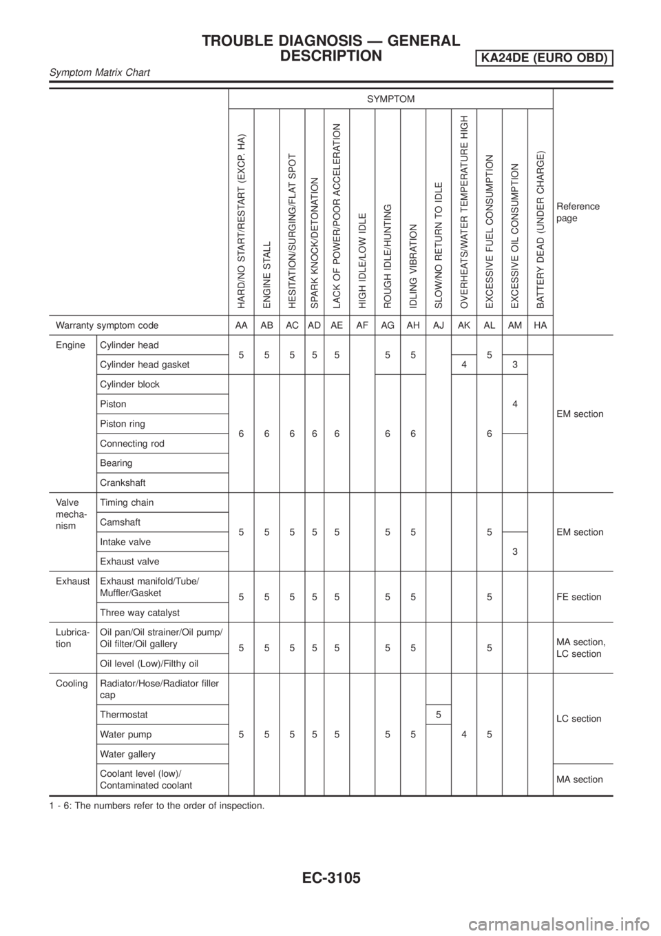
SYMPTOM
Reference
page
HARD/NO START/RESTART (EXCP. HA)
ENGINE STALL
HESITATION/SURGING/FLAT SPOT
SPARK KNOCK/DETONATION
LACK OF POWER/POOR ACCELERATION
HIGH IDLE/LOW IDLE
ROUGH IDLE/HUNTING
IDLING VIBRATION
SLOW/NO RETURN TO IDLE
OVERHEATS/WATER TEMPERATURE HIGH
EXCESSIVE FUEL CONSUMPTION
EXCESSIVE OIL CONSUMPTION
BATTERY DEAD (UNDER CHARGE)
Warranty symptom code AA AB AC AD AE AF AG AH AJ AK AL AM HA
Engine Cylinder head
55555 55 5
EM section Cylinder head gasket 4 3
Cylinder block
66666 66 64 Piston
Piston ring
Connecting rod
Bearing
Crankshaft
Valve
mecha-
nismTiming chain
5 5 5 5 5 5 5 5 EM section Camshaft
Intake valve
3
Exhaust valve
Exhaust Exhaust manifold/Tube/
Muffler/Gasket
5 5 5 5 5 5 5 5 FE section
Three way catalyst
Lubrica-
tionOil pan/Oil strainer/Oil pump/
Oil filter/Oil gallery
55555 55 5MA section,
LC section
Oil level (Low)/Filthy oil
Cooling Radiator/Hose/Radiator filler
cap
55555 55 45LC section Thermostat 5
Water pump
Water gallery
Coolant level (low)/
Contaminated coolantMA section
1 - 6: The numbers refer to the order of inspection.
TROUBLE DIAGNOSIS Ð GENERAL
DESCRIPTION
KA24DE (EURO OBD)
Symptom Matrix Chart
EC-3105
Page 245 of 1306
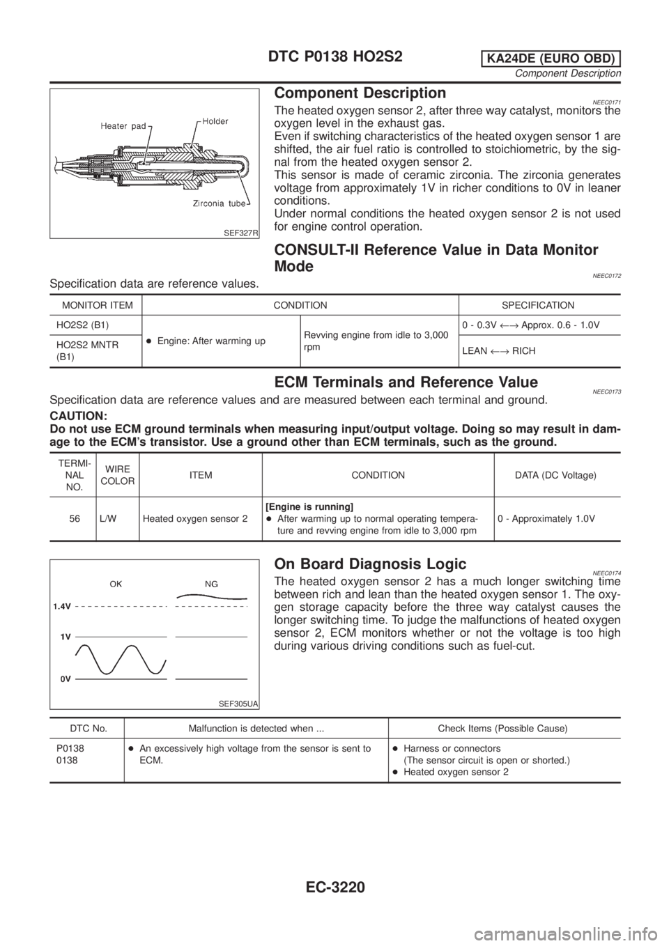
SEF327R
Component DescriptionNEEC0171The heated oxygen sensor 2, after three way catalyst, monitors the
oxygen level in the exhaust gas.
Even if switching characteristics of the heated oxygen sensor 1 are
shifted, the air fuel ratio is controlled to stoichiometric, by the sig-
nal from the heated oxygen sensor 2.
This sensor is made of ceramic zirconia. The zirconia generates
voltage from approximately 1V in richer conditions to 0V in leaner
conditions.
Under normal conditions the heated oxygen sensor 2 is not used
for engine control operation.
CONSULT-II Reference Value in Data Monitor
Mode
NEEC0172Specification data are reference values.
MONITOR ITEM CONDITION SPECIFICATION
HO2S2 (B1)
+Engine: After warming upRevving engine from idle to 3,000
rpm0 - 0.3V¨Approx. 0.6 - 1.0V
HO2S2 MNTR
(B1)LEAN¨RICH
ECM Terminals and Reference ValueNEEC0173Specification data are reference values and are measured between each terminal and ground.
CAUTION:
Do not use ECM ground terminals when measuring input/output voltage. Doing so may result in dam-
age to the ECM's transistor. Use a ground other than ECM terminals, such as the ground.
TERMI-
NAL
NO.WIRE
COLORITEM CONDITION DATA (DC Voltage)
56 L/W Heated oxygen sensor 2[Engine is running]
+After warming up to normal operating tempera-
ture and revving engine from idle to 3,000 rpm0 - Approximately 1.0V
SEF305UA
On Board Diagnosis LogicNEEC0174The heated oxygen sensor 2 has a much longer switching time
between rich and lean than the heated oxygen sensor 1. The oxy-
gen storage capacity before the three way catalyst causes the
longer switching time. To judge the malfunctions of heated oxygen
sensor 2, ECM monitors whether or not the voltage is too high
during various driving conditions such as fuel-cut.
DTC No. Malfunction is detected when ... Check Items (Possible Cause)
P0138
0138+An excessively high voltage from the sensor is sent to
ECM.+Harness or connectors
(The sensor circuit is open or shorted.)
+Heated oxygen sensor 2
DTC P0138 HO2S2KA24DE (EURO OBD)
Component Description
EC-3220
Page 252 of 1306
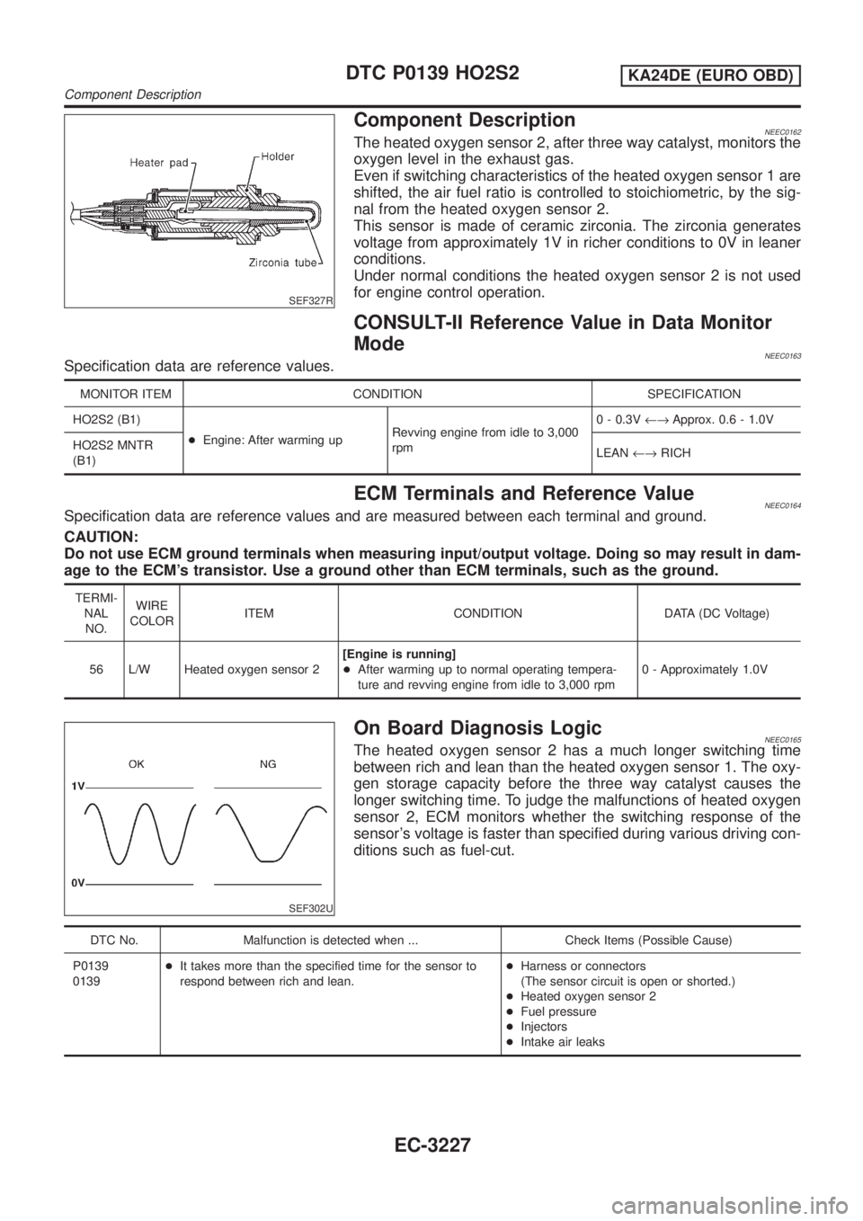
SEF327R
Component DescriptionNEEC0162The heated oxygen sensor 2, after three way catalyst, monitors the
oxygen level in the exhaust gas.
Even if switching characteristics of the heated oxygen sensor 1 are
shifted, the air fuel ratio is controlled to stoichiometric, by the sig-
nal from the heated oxygen sensor 2.
This sensor is made of ceramic zirconia. The zirconia generates
voltage from approximately 1V in richer conditions to 0V in leaner
conditions.
Under normal conditions the heated oxygen sensor 2 is not used
for engine control operation.
CONSULT-II Reference Value in Data Monitor
Mode
NEEC0163Specification data are reference values.
MONITOR ITEM CONDITION SPECIFICATION
HO2S2 (B1)
+Engine: After warming upRevving engine from idle to 3,000
rpm0 - 0.3V¨Approx. 0.6 - 1.0V
HO2S2 MNTR
(B1)LEAN¨RICH
ECM Terminals and Reference ValueNEEC0164Specification data are reference values and are measured between each terminal and ground.
CAUTION:
Do not use ECM ground terminals when measuring input/output voltage. Doing so may result in dam-
age to the ECM's transistor. Use a ground other than ECM terminals, such as the ground.
TERMI-
NAL
NO.WIRE
COLORITEM CONDITION DATA (DC Voltage)
56 L/W Heated oxygen sensor 2[Engine is running]
+After warming up to normal operating tempera-
ture and revving engine from idle to 3,000 rpm0 - Approximately 1.0V
SEF302U
On Board Diagnosis LogicNEEC0165The heated oxygen sensor 2 has a much longer switching time
between rich and lean than the heated oxygen sensor 1. The oxy-
gen storage capacity before the three way catalyst causes the
longer switching time. To judge the malfunctions of heated oxygen
sensor 2, ECM monitors whether the switching response of the
sensor's voltage is faster than specified during various driving con-
ditions such as fuel-cut.
DTC No. Malfunction is detected when ... Check Items (Possible Cause)
P0139
0139+It takes more than the specified time for the sensor to
respond between rich and lean.+Harness or connectors
(The sensor circuit is open or shorted.)
+Heated oxygen sensor 2
+Fuel pressure
+Injectors
+Intake air leaks
DTC P0139 HO2S2KA24DE (EURO OBD)
Component Description
EC-3227