2001 NISSAN PICK-UP fuel cap
[x] Cancel search: fuel capPage 295 of 1306
SEF928V
SEF853B
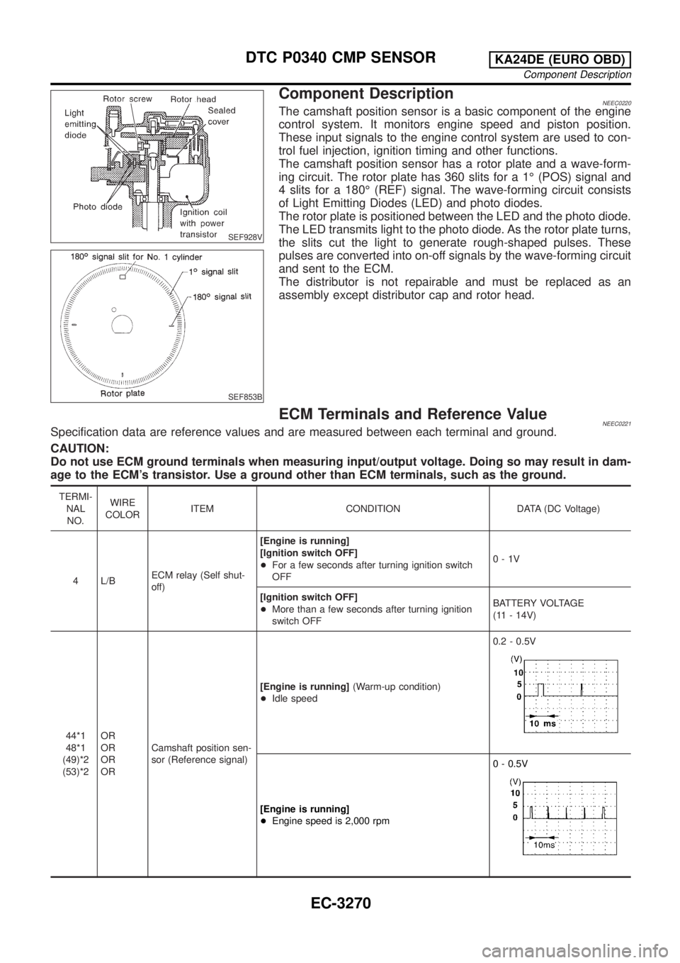
Component DescriptionNEEC0220The camshaft position sensor is a basic component of the engine
control system. It monitors engine speed and piston position.
These input signals to the engine control system are used to con-
trol fuel injection, ignition timing and other functions.
The camshaft position sensor has a rotor plate and a wave-form-
ing circuit. The rotor plate has 360 slits for a 1É (POS) signal and
4 slits for a 180É (REF) signal. The wave-forming circuit consists
of Light Emitting Diodes (LED) and photo diodes.
The rotor plate is positioned between the LED and the photo diode.
The LED transmits light to the photo diode. As the rotor plate turns,
the slits cut the light to generate rough-shaped pulses. These
pulses are converted into on-off signals by the wave-forming circuit
and sent to the ECM.
The distributor is not repairable and must be replaced as an
assembly except distributor cap and rotor head.
ECM Terminals and Reference ValueNEEC0221Specification data are reference values and are measured between each terminal and ground.
CAUTION:
Do not use ECM ground terminals when measuring input/output voltage. Doing so may result in dam-
age to the ECM's transistor. Use a ground other than ECM terminals, such as the ground.
TERMI-
NAL
NO.WIRE
COLORITEM CONDITION DATA (DC Voltage)
4 L/BECM relay (Self shut-
off)[Engine is running]
[Ignition switch OFF]
+For a few seconds after turning ignition switch
OFF0-1V
[Ignition switch OFF]
+More than a few seconds after turning ignition
switch OFFBATTERY VOLTAGE
(11 - 14V)
44*1
48*1
(49)*2
(53)*2OR
OR
OR
ORCamshaft position sen-
sor (Reference signal)[Engine is running](Warm-up condition)
+Idle speed0.2 - 0.5V
[Engine is running]
+Engine speed is 2,000 rpm0 - 0.5V
DTC P0340 CMP SENSORKA24DE (EURO OBD)
Component Description
EC-3270
Page 307 of 1306
7 CHECK IGNITION WIRES
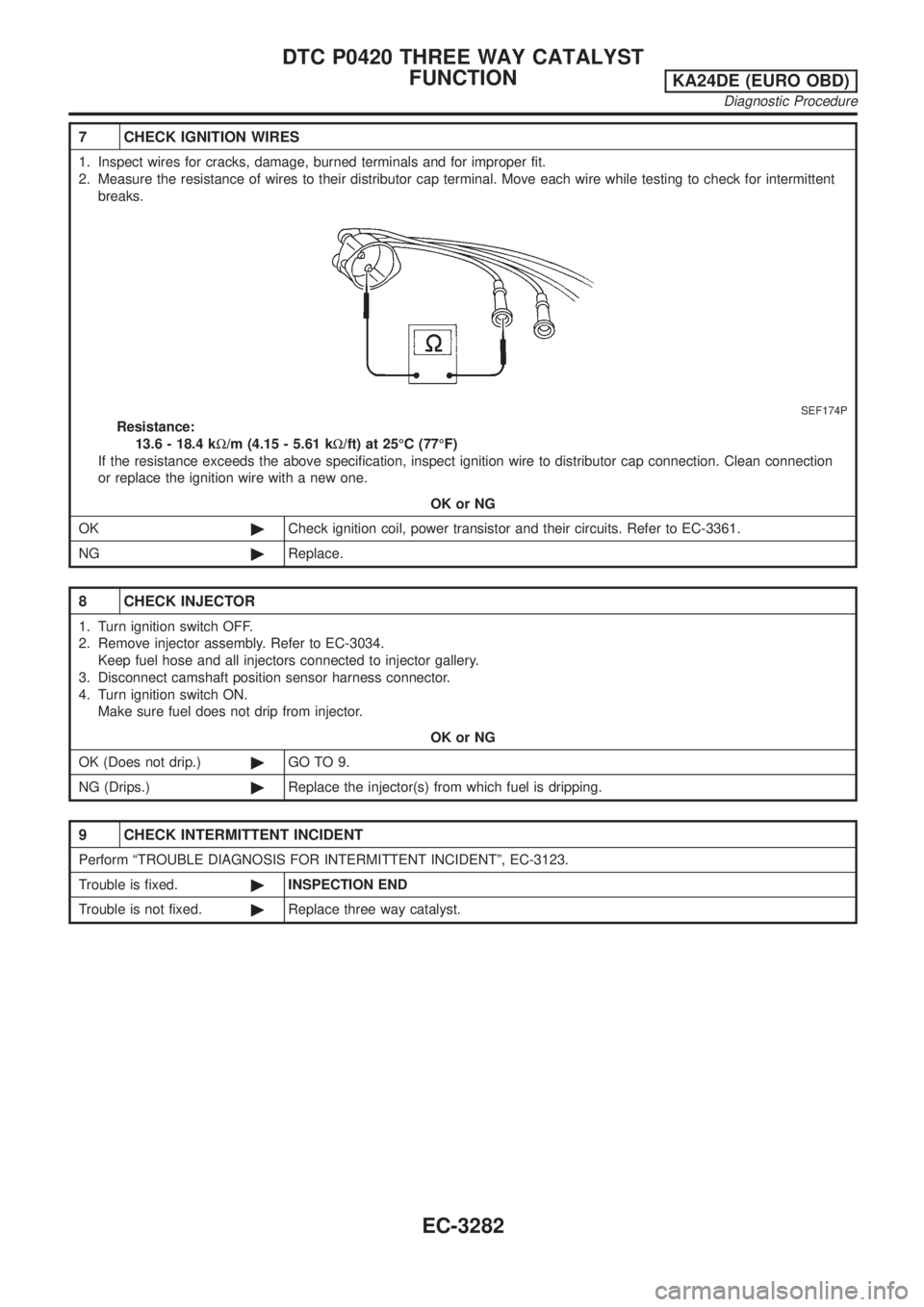
1. Inspect wires for cracks, damage, burned terminals and for improper fit.
2. Measure the resistance of wires to their distributor cap terminal. Move each wire while testing to check for intermittent
breaks.
SEF174P
Resistance:
13.6 - 18.4 kW/m (4.15 - 5.61 kW/ft) at 25ÉC (77ÉF)
If the resistance exceeds the above specification, inspect ignition wire to distributor cap connection. Clean connection
or replace the ignition wire with a new one.
OK or NG
OK©Check ignition coil, power transistor and their circuits. Refer to EC-3361.
NG©Replace.
8 CHECK INJECTOR
1. Turn ignition switch OFF.
2. Remove injector assembly. Refer to EC-3034.
Keep fuel hose and all injectors connected to injector gallery.
3. Disconnect camshaft position sensor harness connector.
4. Turn ignition switch ON.
Make sure fuel does not drip from injector.
OK or NG
OK (Does not drip.)©GO TO 9.
NG (Drips.)©Replace the injector(s) from which fuel is dripping.
9 CHECK INTERMITTENT INCIDENT
Perform ªTROUBLE DIAGNOSIS FOR INTERMITTENT INCIDENTº, EC-3123.
Trouble is fixed.©INSPECTION END
Trouble is not fixed.©Replace three way catalyst.
DTC P0420 THREE WAY CATALYST
FUNCTION
KA24DE (EURO OBD)
Diagnostic Procedure
EC-3282
Page 349 of 1306
SEF327R
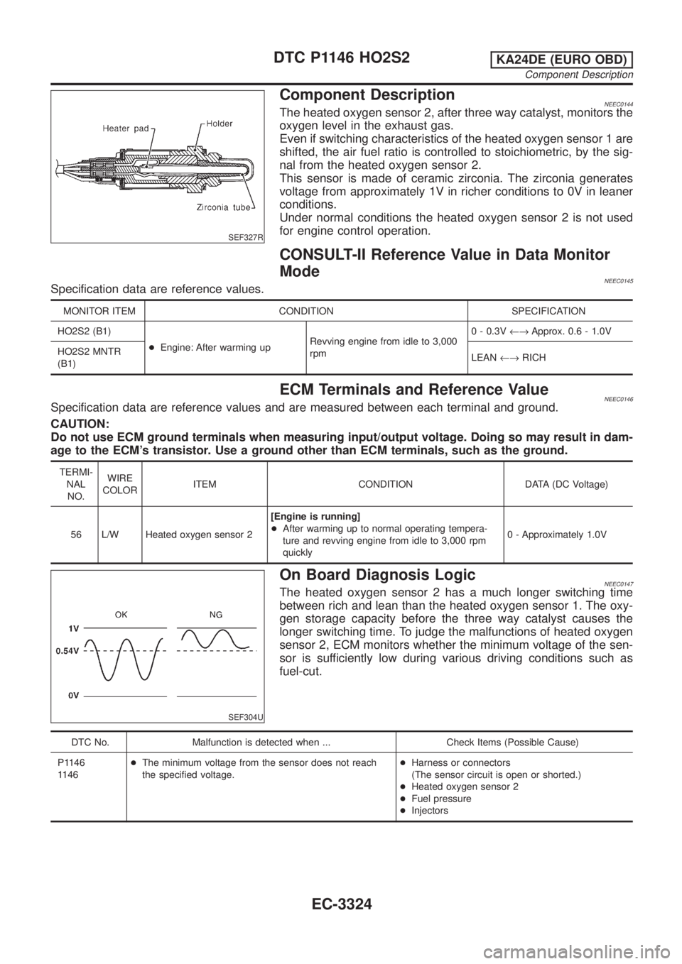
Component DescriptionNEEC0144The heated oxygen sensor 2, after three way catalyst, monitors the
oxygen level in the exhaust gas.
Even if switching characteristics of the heated oxygen sensor 1 are
shifted, the air fuel ratio is controlled to stoichiometric, by the sig-
nal from the heated oxygen sensor 2.
This sensor is made of ceramic zirconia. The zirconia generates
voltage from approximately 1V in richer conditions to 0V in leaner
conditions.
Under normal conditions the heated oxygen sensor 2 is not used
for engine control operation.
CONSULT-II Reference Value in Data Monitor
Mode
NEEC0145Specification data are reference values.
MONITOR ITEM CONDITION SPECIFICATION
HO2S2 (B1)
+Engine: After warming upRevving engine from idle to 3,000
rpm0 - 0.3V¨Approx. 0.6 - 1.0V
HO2S2 MNTR
(B1)LEAN¨RICH
ECM Terminals and Reference ValueNEEC0146Specification data are reference values and are measured between each terminal and ground.
CAUTION:
Do not use ECM ground terminals when measuring input/output voltage. Doing so may result in dam-
age to the ECM's transistor. Use a ground other than ECM terminals, such as the ground.
TERMI-
NAL
NO.WIRE
COLORITEM CONDITION DATA (DC Voltage)
56 L/W Heated oxygen sensor 2[Engine is running]
+After warming up to normal operating tempera-
ture and revving engine from idle to 3,000 rpm
quickly0 - Approximately 1.0V
SEF304U
On Board Diagnosis LogicNEEC0147The heated oxygen sensor 2 has a much longer switching time
between rich and lean than the heated oxygen sensor 1. The oxy-
gen storage capacity before the three way catalyst causes the
longer switching time. To judge the malfunctions of heated oxygen
sensor 2, ECM monitors whether the minimum voltage of the sen-
sor is sufficiently low during various driving conditions such as
fuel-cut.
DTC No. Malfunction is detected when ... Check Items (Possible Cause)
P1146
1146+The minimum voltage from the sensor does not reach
the specified voltage.+Harness or connectors
(The sensor circuit is open or shorted.)
+Heated oxygen sensor 2
+Fuel pressure
+Injectors
DTC P1146 HO2S2KA24DE (EURO OBD)
Component Description
EC-3324
Page 359 of 1306
SEF327R
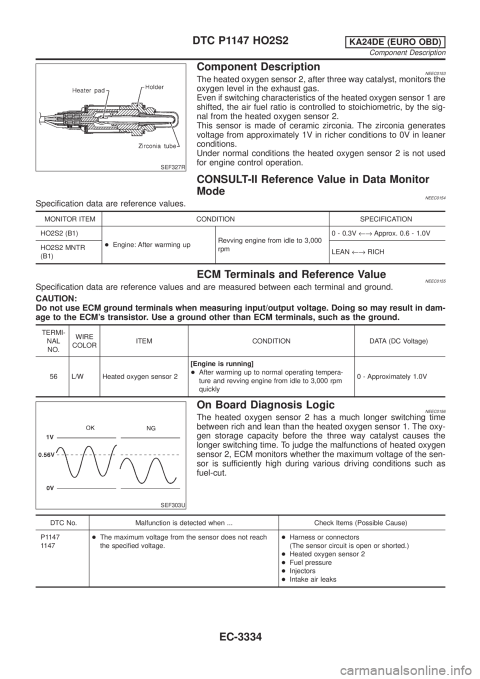
Component DescriptionNEEC0153The heated oxygen sensor 2, after three way catalyst, monitors the
oxygen level in the exhaust gas.
Even if switching characteristics of the heated oxygen sensor 1 are
shifted, the air fuel ratio is controlled to stoichiometric, by the sig-
nal from the heated oxygen sensor 2.
This sensor is made of ceramic zirconia. The zirconia generates
voltage from approximately 1V in richer conditions to 0V in leaner
conditions.
Under normal conditions the heated oxygen sensor 2 is not used
for engine control operation.
CONSULT-II Reference Value in Data Monitor
Mode
NEEC0154Specification data are reference values.
MONITOR ITEM CONDITION SPECIFICATION
HO2S2 (B1)
+Engine: After warming upRevving engine from idle to 3,000
rpm0 - 0.3V¨Approx. 0.6 - 1.0V
HO2S2 MNTR
(B1)LEAN¨RICH
ECM Terminals and Reference ValueNEEC0155Specification data are reference values and are measured between each terminal and ground.
CAUTION:
Do not use ECM ground terminals when measuring input/output voltage. Doing so may result in dam-
age to the ECM's transistor. Use a ground other than ECM terminals, such as the ground.
TERMI-
NAL
NO.WIRE
COLORITEM CONDITION DATA (DC Voltage)
56 L/W Heated oxygen sensor 2[Engine is running]
+After warming up to normal operating tempera-
ture and revving engine from idle to 3,000 rpm
quickly0 - Approximately 1.0V
SEF303U
On Board Diagnosis LogicNEEC0156The heated oxygen sensor 2 has a much longer switching time
between rich and lean than the heated oxygen sensor 1. The oxy-
gen storage capacity before the three way catalyst causes the
longer switching time. To judge the malfunctions of heated oxygen
sensor 2, ECM monitors whether the maximum voltage of the sen-
sor is sufficiently high during various driving conditions such as
fuel-cut.
DTC No. Malfunction is detected when ... Check Items (Possible Cause)
P1147
1147+The maximum voltage from the sensor does not reach
the specified voltage.+Harness or connectors
(The sensor circuit is open or shorted.)
+Heated oxygen sensor 2
+Fuel pressure
+Injectors
+Intake air leaks
DTC P1147 HO2S2KA24DE (EURO OBD)
Component Description
EC-3334
Page 440 of 1306
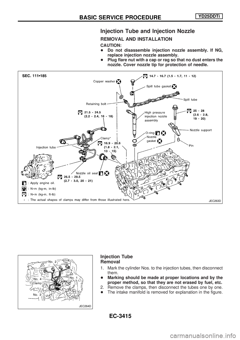
Injection Tube and Injection Nozzle
REMOVAL AND INSTALLATION
CAUTION:
+Do not disassemble injection nozzle assembly. If NG,
replace injection nozzle assembly.
+Plug flare nut with a cap or rag so that no dust enters the
nozzle. Cover nozzle tip for protection of needle.
Injection Tube
Removal
1. Mark the cylinder Nos. to the injection tubes, then disconnect
them.
+Marking should be made at proper locations and by the
proper method, so that they are not erased by fuel, etc.
2. Remove the clamps, then disconnect the tubes one by one.
+The intake manifold is removed for explanation in the figure.
JEC263D
JEC264D
BASIC SERVICE PROCEDUREYD25DDTi
EC-3415
Page 702 of 1306
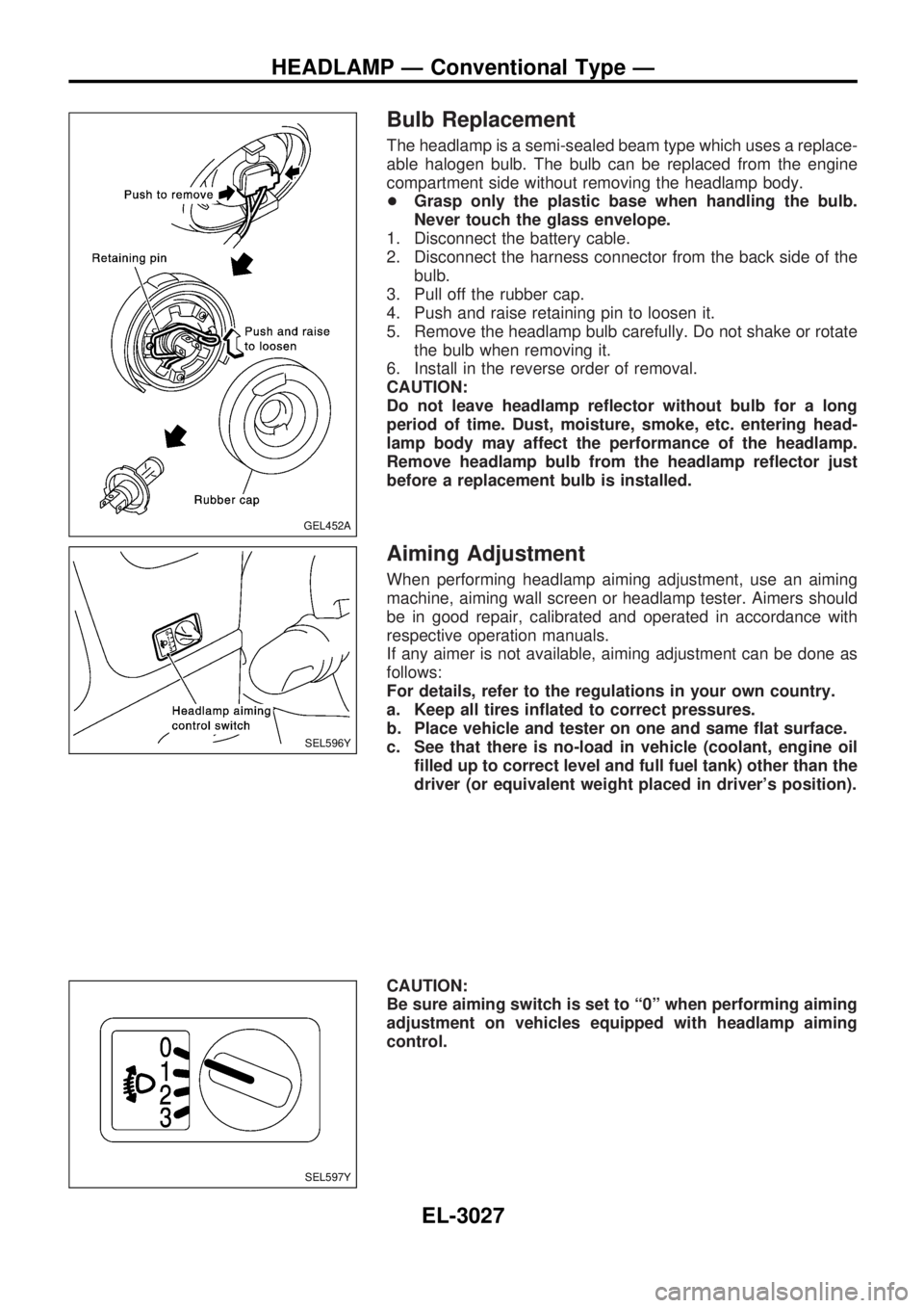
Bulb Replacement
The headlamp is a semi-sealed beam type which uses a replace-
able halogen bulb. The bulb can be replaced from the engine
compartment side without removing the headlamp body.
+Grasp only the plastic base when handling the bulb.
Never touch the glass envelope.
1. Disconnect the battery cable.
2. Disconnect the harness connector from the back side of the
bulb.
3. Pull off the rubber cap.
4. Push and raise retaining pin to loosen it.
5. Remove the headlamp bulb carefully. Do not shake or rotate
the bulb when removing it.
6. Install in the reverse order of removal.
CAUTION:
Do not leave headlamp reflector without bulb for a long
period of time. Dust, moisture, smoke, etc. entering head-
lamp body may affect the performance of the headlamp.
Remove headlamp bulb from the headlamp reflector just
before a replacement bulb is installed.
Aiming Adjustment
When performing headlamp aiming adjustment, use an aiming
machine, aiming wall screen or headlamp tester. Aimers should
be in good repair, calibrated and operated in accordance with
respective operation manuals.
If any aimer is not available, aiming adjustment can be done as
follows:
For details, refer to the regulations in your own country.
a. Keep all tires inflated to correct pressures.
b. Place vehicle and tester on one and same flat surface.
c. See that there is no-load in vehicle (coolant, engine oil
filled up to correct level and full fuel tank) other than the
driver (or equivalent weight placed in driver's position).
CAUTION:
Be sure aiming switch is set to ª0º when performing aiming
adjustment on vehicles equipped with headlamp aiming
control.
GEL452A
SEL596Y
SEL597Y
HEADLAMP Ð Conventional Type Ð
EL-3027
Page 941 of 1306
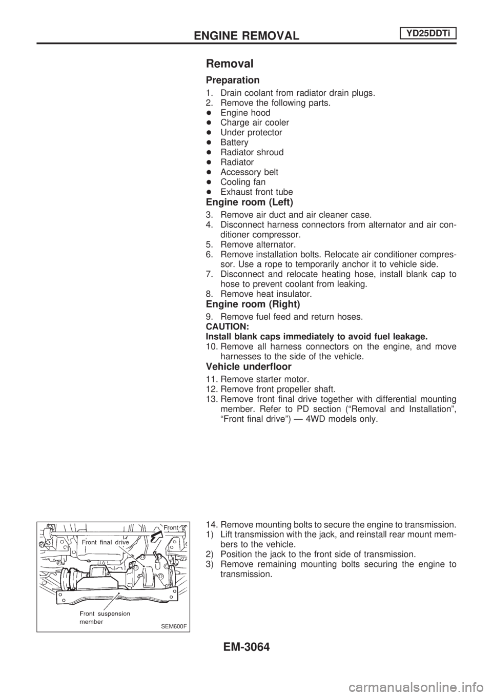
Removal
Preparation
1. Drain coolant from radiator drain plugs.
2. Remove the following parts.
+Engine hood
+Charge air cooler
+Under protector
+Battery
+Radiator shroud
+Radiator
+Accessory belt
+Cooling fan
+Exhaust front tube
Engine room (Left)
3. Remove air duct and air cleaner case.
4. Disconnect harness connectors from alternator and air con-
ditioner compressor.
5. Remove alternator.
6. Remove installation bolts. Relocate air conditioner compres-
sor. Use a rope to temporarily anchor it to vehicle side.
7. Disconnect and relocate heating hose, install blank cap to
hose to prevent coolant from leaking.
8. Remove heat insulator.
Engine room (Right)
9. Remove fuel feed and return hoses.
CAUTION:
Install blank caps immediately to avoid fuel leakage.
10. Remove all harness connectors on the engine, and move
harnesses to the side of the vehicle.
Vehicle underfloor
11. Remove starter motor.
12. Remove front propeller shaft.
13. Remove front final drive together with differential mounting
member. Refer to PD section (ªRemoval and Installationº,
ªFront final driveº) Ð 4WD models only.
14. Remove mounting bolts to secure the engine to transmission.
1) Lift transmission with the jack, and reinstall rear mount mem-
bers to the vehicle.
2) Position the jack to the front side of transmission.
3) Remove remaining mounting bolts securing the engine to
transmission.
SEM600F
ENGINE REMOVALYD25DDTi
EM-3064
Page 945 of 1306
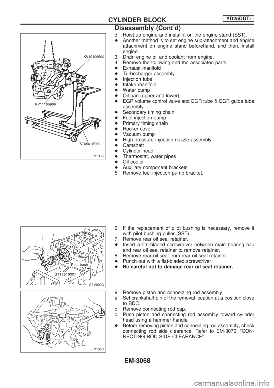
d. Hoist up engine and install it on the engine stand (SST).
+Another method is to set engine sub-attachment and engine
attachment on engine stand beforehand, and then, install
engine.
3. Drain engine oil and coolant from engine.
4. Remove the following and the associated parts:
+Exhaust manifold
+Turbocharger assembly
+Injection tube
+Intake manifold
+Water pump
+Oil pan (upper and lower)
+EGR volume control valve and EGR tube & EGR guide tube
assembly
+Secondary timing chain
+Fuel injection pump
+Primary timing chain
+Rocker cover
+Vacuum pump
+High pressure injection nozzle assembly
+Camshaft
+Cylinder head
+Thermostat, water pipes
+Oil cooler
+Auxiliary component brackets
5. Remove fuel injection pump bracket.
6. If the replacement of pilot bushing is necessary, remove it
with pilot bushing puller (SST).
7. Remove rear oil seal retainer.
+Insert a flat-bladed screwdriver between main bearing cap
and rear oil seal retainer to remove retainer.
8. Remove rear oil seal from rear oil seal retainer.
+Punch out with a flat-bladed screwdriver.
+Be careful not to damage rear oil seal retainer.
9. Remove piston and connecting rod assembly.
a. Set crankshaft pin of the removal location at a position close
to BDC.
b. Remove connecting rod cap.
c. Push piston and connecting rod assembly toward cylinder
head using a hammer handle.
+Before removing piston and connecting rod assembly, check
connecting rod side clearance. Refer to EM-3070, ªCON-
NECTING ROD SIDE CLEARANCEº.
JEM193G
SEM500G
JEM195G
CYLINDER BLOCKYD25DDTi
Disassembly (Cont'd)
EM-3068