2001 NISSAN PICK-UP remote start
[x] Cancel search: remote startPage 676 of 1306

ELECTRICAL SYSTEM
SECTION
EL
MODIFICATION NOTICE:
+Wiring diagrams have been changed.
+Combination meter has been changed.
+Headlamp has been changed.
+Headlamp aiming control has been added.
+Headlamp washer has been added.
+A hazard reminder feature has been added to the multi-remote control system.
+NATS (Nissan Anti-Theft System) has been changed.
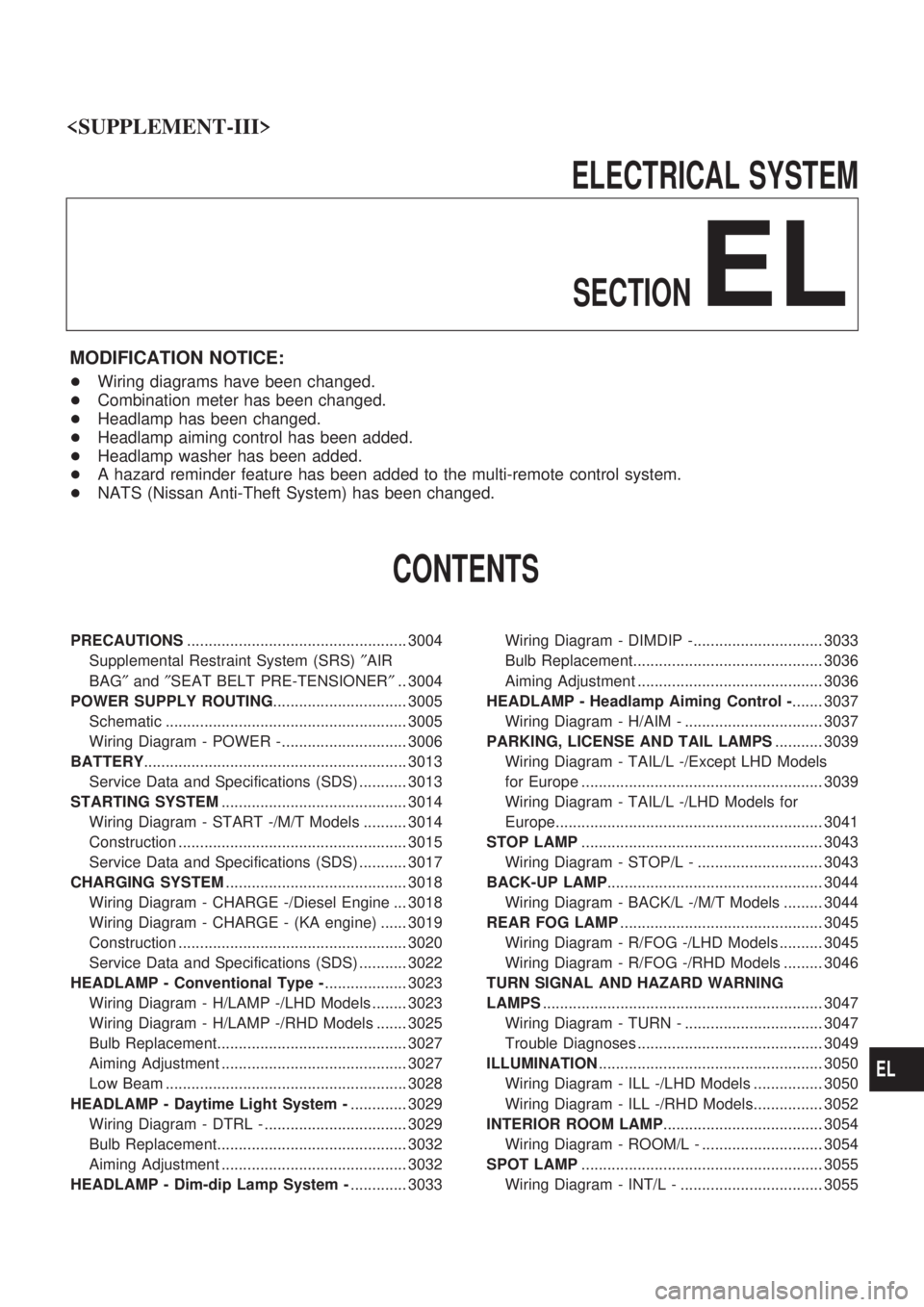
CONTENTS
PRECAUTIONS................................................... 3004
Supplemental Restraint System (SRS)²AIR
BAG²and²SEAT BELT PRE-TENSIONER².. 3004
POWER SUPPLY ROUTING............................... 3005
Schematic ........................................................ 3005
Wiring Diagram - POWER -............................. 3006
BATTERY............................................................. 3013
Service Data and Specifications (SDS) ........... 3013
STARTING SYSTEM........................................... 3014
Wiring Diagram - START -/M/T Models .......... 3014
Construction ..................................................... 3015
Service Data and Specifications (SDS) ........... 3017
CHARGING SYSTEM.......................................... 3018
Wiring Diagram - CHARGE -/Diesel Engine ... 3018
Wiring Diagram - CHARGE - (KA engine) ...... 3019
Construction ..................................................... 3020
Service Data and Specifications (SDS) ........... 3022
HEADLAMP - Conventional Type -................... 3023
Wiring Diagram - H/LAMP -/LHD Models ........ 3023
Wiring Diagram - H/LAMP -/RHD Models ....... 3025
Bulb Replacement............................................ 3027
Aiming Adjustment ........................................... 3027
Low Beam ........................................................ 3028
HEADLAMP - Daytime Light System -............. 3029
Wiring Diagram - DTRL - ................................. 3029
Bulb Replacement............................................ 3032
Aiming Adjustment ........................................... 3032
HEADLAMP - Dim-dip Lamp System -............. 3033Wiring Diagram - DIMDIP -.............................. 3033
Bulb Replacement............................................ 3036
Aiming Adjustment ........................................... 3036
HEADLAMP - Headlamp Aiming Control -....... 3037
Wiring Diagram - H/AIM - ................................ 3037
PARKING, LICENSE AND TAIL LAMPS........... 3039
Wiring Diagram - TAIL/L -/Except LHD Models
for Europe ........................................................ 3039
Wiring Diagram - TAIL/L -/LHD Models for
Europe.............................................................. 3041
STOP LAMP........................................................ 3043
Wiring Diagram - STOP/L - ............................. 3043
BACK-UP LAMP.................................................. 3044
Wiring Diagram - BACK/L -/M/T Models ......... 3044
REAR FOG LAMP............................................... 3045
Wiring Diagram - R/FOG -/LHD Models .......... 3045
Wiring Diagram - R/FOG -/RHD Models ......... 3046
TURN SIGNAL AND HAZARD WARNING
LAMPS................................................................. 3047
Wiring Diagram - TURN - ................................ 3047
Trouble Diagnoses ........................................... 3049
ILLUMINATION.................................................... 3050
Wiring Diagram - ILL -/LHD Models ................ 3050
Wiring Diagram - ILL -/RHD Models................ 3052
INTERIOR ROOM LAMP..................................... 3054
Wiring Diagram - ROOM/L - ............................ 3054
SPOT LAMP........................................................ 3055
Wiring Diagram - INT/L - ................................. 3055
EL
Page 813 of 1306

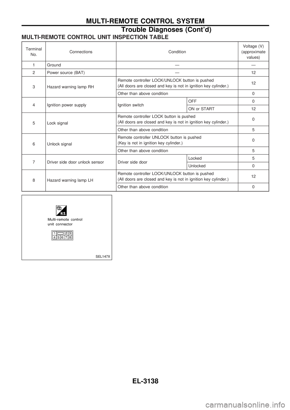
MULTI-REMOTE CONTROL UNIT INSPECTION TABLE
Terminal
No.Connections ConditionVoltage (V)
(approximate
values)
1 Ground Ð Ð
2 Power source (BAT) Ð 12
3 Hazard warning lamp RHRemote controller LOCK/UNLOCK button is pushed
(All doors are closed and key is not in ignition key cylinder.)12
Other than above condition 0
4 Ignition power supply Ignition switchOFF 0
ON or START 12
5 Lock signalRemote controller LOCK button is pushed
(All doors are closed and key is not in ignition key cylinder.)0
Other than above condition 5
6 Unlock signalRemote controller UNLOCK button is pushed
(Key is not in ignition key cylinder.)0
Other than above condition 5
7 Driver side door unlock sensor Driver side doorLocked 5
Unlocked 0
8 Hazard warning lamp LHRemote controller LOCK/UNLOCK button is pushed
(All doors are closed and key is not in ignition key cylinder.)12
Other than above condition 0
SEL147X
MULTI-REMOTE CONTROL SYSTEM
Trouble Diagnoses (Cont'd)
EL-3138
Page 1112 of 1306

ELECTRICAL SYSTEM
SECTION
EL
MODIFICATION NOTICE:
+Wiring diagrams have been changed.
+Combination meter has been changed.
+Headlamp has been changed.
+Headlamp aiming control has been added.
+Headlamp washer has been added.
+A hazard reminder feature has been added to the multi-remote control system.
+NATS (Nissan Anti-Theft System) has been changed.
CONTENTS
PRECAUTIONS................................................... 3004
Supplemental Restraint System (SRS)²AIR
BAG²and²SEAT BELT PRE-TENSIONER².. 3004
POWER SUPPLY ROUTING............................... 3005
Schematic ........................................................ 3005
Wiring Diagram - POWER -............................. 3006
BATTERY............................................................. 3013
Service Data and Specifications (SDS) ........... 3013
STARTING SYSTEM........................................... 3014
Wiring Diagram - START -/M/T Models .......... 3014
Construction ..................................................... 3015
Service Data and Specifications (SDS) ........... 3017
CHARGING SYSTEM.......................................... 3018
Wiring Diagram - CHARGE -/Diesel Engine ... 3018
Wiring Diagram - CHARGE - (KA engine) ...... 3019
Construction ..................................................... 3020
Service Data and Specifications (SDS) ........... 3022
HEADLAMP - Conventional Type -................... 3023
Wiring Diagram - H/LAMP -/LHD Models ........ 3023
Wiring Diagram - H/LAMP -/RHD Models ....... 3025
Bulb Replacement............................................ 3027
Aiming Adjustment ........................................... 3027
Low Beam ........................................................ 3028
HEADLAMP - Daytime Light System -............. 3029
Wiring Diagram - DTRL - ................................. 3029
Bulb Replacement............................................ 3032
Aiming Adjustment ........................................... 3032
HEADLAMP - Dim-dip Lamp System -............. 3033Wiring Diagram - DIMDIP -.............................. 3033
Bulb Replacement............................................ 3036
Aiming Adjustment ........................................... 3036
HEADLAMP - Headlamp Aiming Control -....... 3037
Wiring Diagram - H/AIM - ................................ 3037
PARKING, LICENSE AND TAIL LAMPS........... 3039
Wiring Diagram - TAIL/L -/Except LHD Models
for Europe ........................................................ 3039
Wiring Diagram - TAIL/L -/LHD Models for
Europe.............................................................. 3041
STOP LAMP........................................................ 3043
Wiring Diagram - STOP/L - ............................. 3043
BACK-UP LAMP.................................................. 3044
Wiring Diagram - BACK/L -/M/T Models ......... 3044
REAR FOG LAMP............................................... 3045
Wiring Diagram - R/FOG -/LHD Models .......... 3045
Wiring Diagram - R/FOG -/RHD Models ......... 3046
TURN SIGNAL AND HAZARD WARNING
LAMPS................................................................. 3047
Wiring Diagram - TURN - ................................ 3047
Trouble Diagnoses ........................................... 3049
ILLUMINATION.................................................... 3050
Wiring Diagram - ILL -/LHD Models ................ 3050
Wiring Diagram - ILL -/RHD Models................ 3052
INTERIOR ROOM LAMP..................................... 3054
Wiring Diagram - ROOM/L - ............................ 3054
SPOT LAMP........................................................ 3055
Wiring Diagram - INT/L - ................................. 3055
EL
Page 1249 of 1306

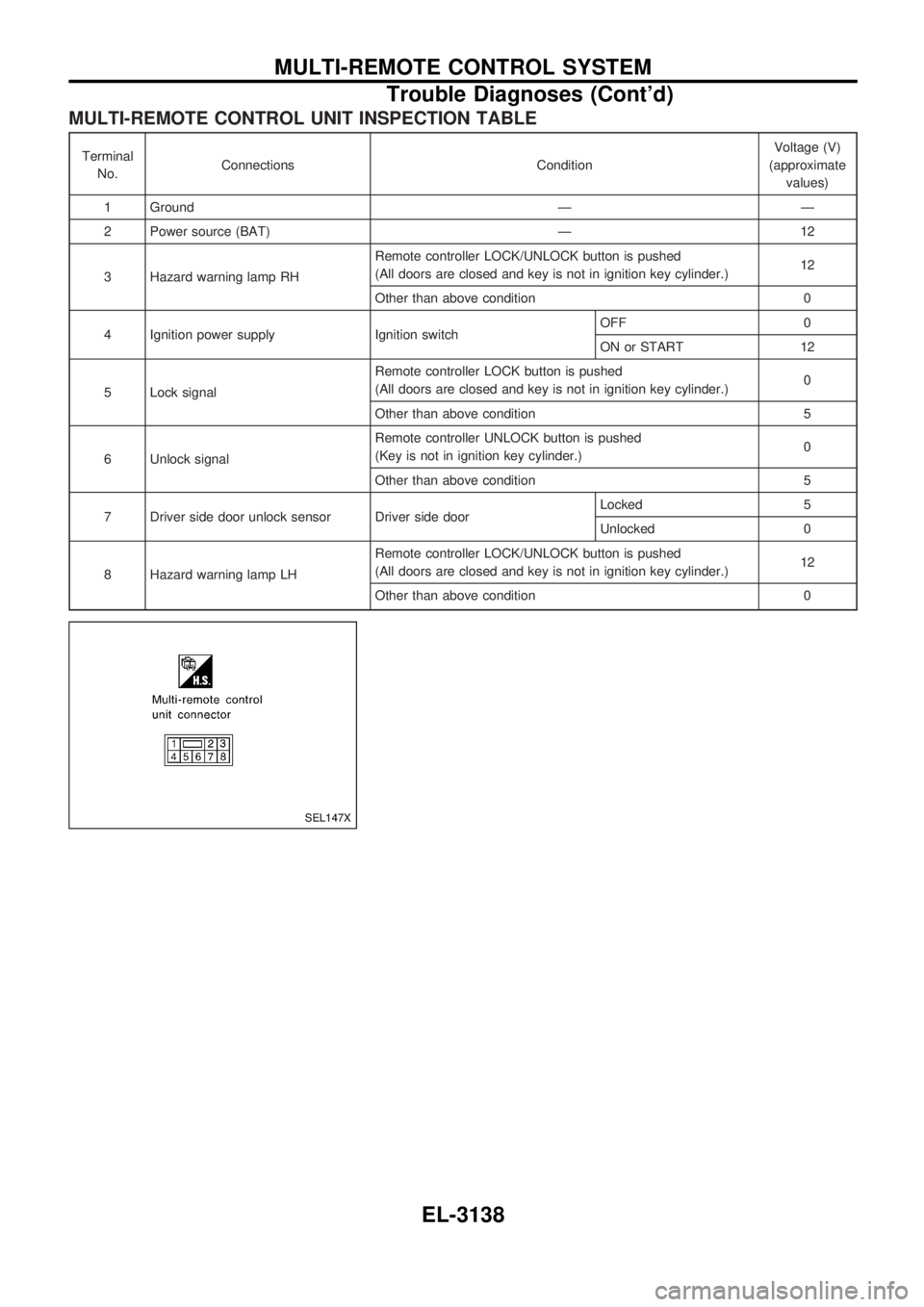
MULTI-REMOTE CONTROL UNIT INSPECTION TABLE
Terminal
No.Connections ConditionVoltage (V)
(approximate
values)
1 Ground Ð Ð
2 Power source (BAT) Ð 12
3 Hazard warning lamp RHRemote controller LOCK/UNLOCK button is pushed
(All doors are closed and key is not in ignition key cylinder.)12
Other than above condition 0
4 Ignition power supply Ignition switchOFF 0
ON or START 12
5 Lock signalRemote controller LOCK button is pushed
(All doors are closed and key is not in ignition key cylinder.)0
Other than above condition 5
6 Unlock signalRemote controller UNLOCK button is pushed
(Key is not in ignition key cylinder.)0
Other than above condition 5
7 Driver side door unlock sensor Driver side doorLocked 5
Unlocked 0
8 Hazard warning lamp LHRemote controller LOCK/UNLOCK button is pushed
(All doors are closed and key is not in ignition key cylinder.)12
Other than above condition 0
SEL147X
MULTI-REMOTE CONTROL SYSTEM
Trouble Diagnoses (Cont'd)
EL-3138