2001 NISSAN PICK-UP relay
[x] Cancel search: relayPage 48 of 1306

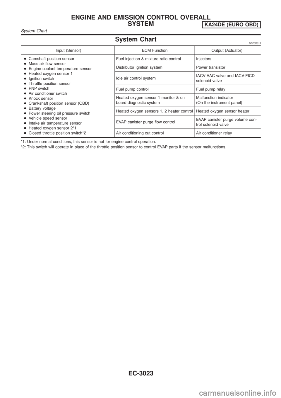
System ChartNEEC0013
Input (Sensor) ECM Function Output (Actuator)
+Camshaft position sensor
+Mass air flow sensor
+Engine coolant temperature sensor
+Heated oxygen sensor 1
+Ignition switch
+Throttle position sensor
+PNP switch
+Air conditioner switch
+Knock sensor
+Crankshaft position sensor (OBD)
+Battery voltage
+Power steering oil pressure switch
+Vehicle speed sensor
+Intake air temperature sensor
+Heated oxygen sensor 2*1
+Closed throttle position switch*2Fuel injection & mixture ratio control Injectors
Distributor ignition system Power transistor
Idle air control systemIACV-AAC valve and IACV-FICD
solenoid valve
Fuel pump control Fuel pump relay
Heated oxygen sensor 1 monitor & on
board diagnostic systemMalfunction indicator
(On the instrument panel)
Heated oxygen sensors 1, 2 heater control Heated oxygen sensor heater
EVAP canister purge flow controlEVAP canister purge volume con-
trol solenoid valve
Air conditioning cut control Air conditioner relay
*1: Under normal conditions, this sensor is not for engine control operation.
*2: This switch will operate in place of the throttle position sensor to control EVAP parts if the sensor malfunctions.
ENGINE AND EMISSION CONTROL OVERALL
SYSTEM
KA24DE (EURO OBD)
System Chart
EC-3023
Page 53 of 1306

Air Conditioning Cut Control
DESCRIPTION=NEEC0016Input/Output Signal ChartNEEC0016S01
Sensor Input Signal to ECMECM func-
tionActuator
Air conditioner switch Air conditioner ªONº signal
Air condi-
tioner cut
controlAir conditioner relay Throttle position sensor Throttle valve opening angle
Camshaft position sensor Engine speed
Engine coolant temperature sensor Engine coolant temperature
Ignition switch Start signal
Vehicle speed sensor Vehicle speed
Power steering oil pressure switch Power steering operation
System DescriptionNEEC0016S02This system improves engine operation when the air conditioner is used.
Under the following conditions, the air conditioner is turned off.
+When the accelerator pedal is fully depressed.
+When cranking the engine.
+When the engine coolant temperature becomes excessively high.
+When operating power steering and air conditioner during low engine speed or when fully releasing accel-
erator pedal.
+When engine speed is excessively low.
Fuel Cut Control (at no load & high engine
speed)
DESCRIPTIONNEEC0017Input/Output Signal ChartNEEC0017S01
Sensor Input Signal to ECMECM func-
tionActuator
Vehicle speed sensor Vehicle speed
Fuel cut
controlInjectors PNP switch Neutral position
Throttle position sensor Throttle position
Camshaft position sensor Engine speed
If the engine speed is above 3,000 rpm with no load, (for example, in Neutral and engine speed over 3,000
rpm) fuel will be cut off after some time. The exact time when the fuel is cut off varies based on engine speed.
Fuel cut will operate until the engine speed reaches 1,500 rpm, then fuel cut is cancelled.
NOTE:
This function is different from deceleration control listed under ªMultiport Fuel Injection (MFI) Systemº,
EC-3024.
ENGINE AND EMISSION BASIC CONTROL SYSTEM
DESCRIPTION
KA24DE (EURO OBD)
Air Conditioning Cut Control
EC-3028
Page 97 of 1306

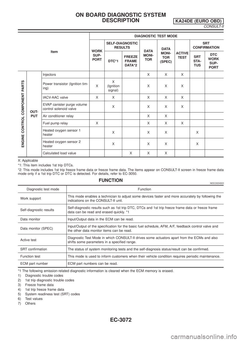
ItemDIAGNOSTIC TEST MODE
WORK
SUP-
PORTSELF-DIAGNOSTIC
RESULTS
DATA
MONI-
TORDATA
MONI-
TOR
(SPEC)ACTIVE
TESTSRT
CONFIRMATION
DTC*1FREEZE
FRAME
DATA*2SRT
STA-
TUSDTC
WORK
SUP-
PORT
ENGINE CONTROL COMPONENT PARTS
OUT-
PUTInjectors X X X
Power transistor (Ignition tim-
ing)XX
(Ignition
signal)XXX
IACV-AAC valve X X X X X
EVAP canister purge volume
control solenoid valveXXXX
Air conditioner relay X X
Fuel pump relay X X X X
Heated oxygen sensor 1
heaterXXXX
Heated oxygen sensor 2
heaterXXXX
Calculated load value X X X
X: Applicable
*1: This item includes 1st trip DTCs.
*2: This mode includes 1st trip freeze frame data or freeze frame data. The items appear on CONSULT-II screen in freeze frame data
mode only if a 1st trip DTC or DTC is detected. For details, refer to EC-3050.
FUNCTIONNEEC0034S03
Diagnostic test mode Function
Work supportThis mode enables a technician to adjust some devices faster and more accurately by following the
indications on the CONSULT-II unit.
Self-diagnostic resultsSelf-diagnostic results such as 1st trip DTC, DTCs and 1st trip freeze frame data or freeze frame
data can be read and erased quickly. *1
Data monitor Input/Output data in the ECM can be read.
Data monitor (SPEC)Input/Output of the specification for the basic fuel schedule, AFM, A/F, feedback control valve and
the other data monitor items can be read.
Active testDiagnostic Test Mode in which CONSULT-II drives some actuators apart from the ECMs and also
shifts some parameters in a specified range.
SRT confirmation The status of system monitoring tests and the self-diagnosis status/result can be confirmed.
Function test This mode is used to inform customers when their vehicle condition requires periodic maintenance.
ECM part number ECM part numbers can be read.
*1 The following emission-related diagnostic information is cleared when the ECM memory is erased.
1) Diagnostic trouble codes
2) 1st trip diagnostic trouble codes
3) Freeze frame data
4) 1st trip freeze frame data
5) System readiness test (SRT) codes
6) Test values
7) Others
ON BOARD DIAGNOSTIC SYSTEM
DESCRIPTION
KA24DE (EURO OBD)
CONSULT-II
EC-3072
Page 101 of 1306
![NISSAN PICK-UP 2001 Repair Manual Monitored item [Unit]ECM
input
signalsMain
signalsDescription Remarks
AIR COND RLY
[ON/OFF]j+Indicates the air conditioner relay con-
trol condition determined by ECM
according to the input signals.
F NISSAN PICK-UP 2001 Repair Manual Monitored item [Unit]ECM
input
signalsMain
signalsDescription Remarks
AIR COND RLY
[ON/OFF]j+Indicates the air conditioner relay con-
trol condition determined by ECM
according to the input signals.
F](/manual-img/5/57372/w960_57372-100.png)
Monitored item [Unit]ECM
input
signalsMain
signalsDescription Remarks
AIR COND RLY
[ON/OFF]j+Indicates the air conditioner relay con-
trol condition determined by ECM
according to the input signals.
FUEL PUMP RLY
[ON/OFF]j+Indicates the fuel pump relay control
condition determined by ECM accord-
ing to the input signals.
HO2S1 HTR (B1)
[ON/OFF]+Indicates [ON/OFF] condition of heated
oxygen sensor 1 heater determined by
ECM according to the input signals.
HO2S2 HTR (B1)
[ON/OFF]+Indicates [ON/OFF] condition of heated
oxygen sensor 2 heater determined by
ECM according to the input signals.
VOLTAGE [V]+Voltage measured by the voltage
probe.
TRVL AFTER MIL
[km] or [Mile]+Distance traveled while MI is activated.
Frequency
[msec] or [Hz] or [%]+Pulse width, frequency or duty cycle
measured by the pulse probe.+Only ª#º is displayed if item is unable
to be measured.
+Figures with ª#ºs are temporary ones.
They are the same figures as an
actual piece of data which was just
previously measured.
NOTE:
Any monitored item that does not match the vehicle being diagnosed is deleted from the display automatically.
DATA MONITOR (SPEC) MODENEEC0034S12
Monitored item [Unit]ECM
input
signalsMain
signalsDescription Remarks
ENG SPEED [rpm]jj+Indicates the engine speed computed
from the REF signal (180É signal) of
the camshaft position sensor.
MAS A/F SE-B1 [V]jj+The signal voltage of the mass air flow
sensor specification is displayed.+When engine is running specification
range is indicated.
B/FUEL SCHDL
[msec]j+ªBase fuel scheduleº indicates the fuel
injection pulse width programmed into
ECM, prior to any learned on board
correction.+When engine is running specification
range is indicated.
A/F ALPHA-B1 [%]j+The mean value of the air-fuel ratio
feedback correction factor per cycle is
indicated.+When engine is running specification
range is indicated.
+This data also includes the data for the
air-fuel ratio learning control.
NOTE:
Any monitored item that does not match the vehicle being diagnosed is deleted from the display automatically.
ACTIVE TEST MODENEEC0034S07
TEST ITEM CONDITION JUDGEMENT CHECK ITEM (REMEDY)
FUEL INJECTION+Engine: Return to the original
trouble condition
+Change the amount of fuel injec-
tion using CONSULT-II.If trouble symptom disappears, see
CHECK ITEM.+Harness and connector
+Fuel injectors
+Heated oxygen sensor 1
ON BOARD DIAGNOSTIC SYSTEM
DESCRIPTION
KA24DE (EURO OBD)
CONSULT-II
EC-3076
Page 102 of 1306

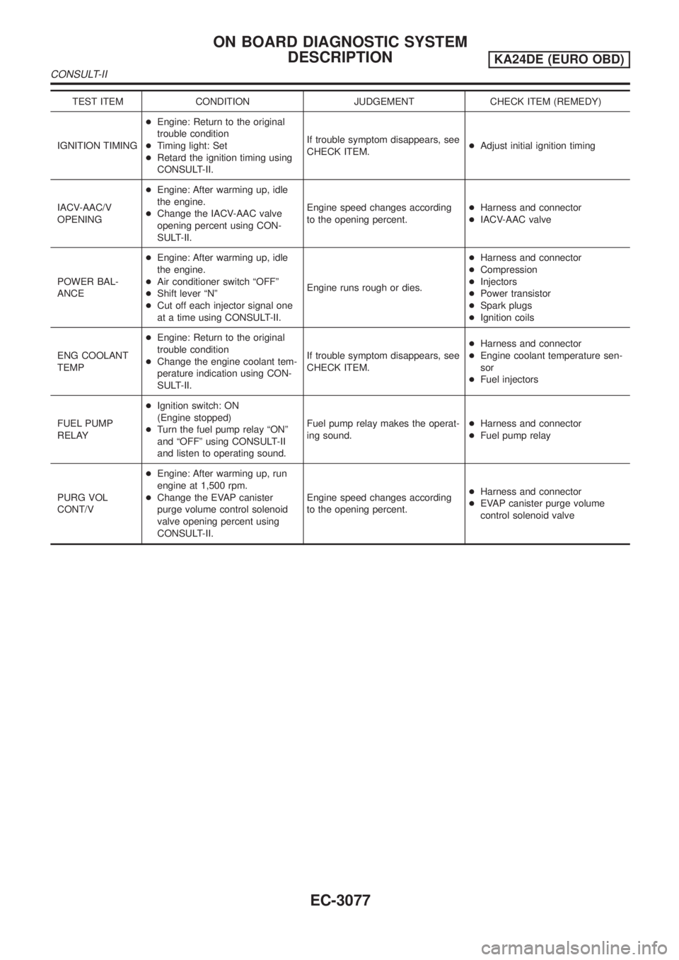
TEST ITEM CONDITION JUDGEMENT CHECK ITEM (REMEDY)
IGNITION TIMING+Engine: Return to the original
trouble condition
+Timing light: Set
+Retard the ignition timing using
CONSULT-II.If trouble symptom disappears, see
CHECK ITEM.+Adjust initial ignition timing
IACV-AAC/V
OPENING+Engine: After warming up, idle
the engine.
+Change the IACV-AAC valve
opening percent using CON-
SULT-II.Engine speed changes according
to the opening percent.+Harness and connector
+IACV-AAC valve
POWER BAL-
ANCE+Engine: After warming up, idle
the engine.
+Air conditioner switch ªOFFº
+Shift lever ªNº
+Cut off each injector signal one
at a time using CONSULT-II.Engine runs rough or dies.+Harness and connector
+Compression
+Injectors
+Power transistor
+Spark plugs
+Ignition coils
ENG COOLANT
TEMP+Engine: Return to the original
trouble condition
+Change the engine coolant tem-
perature indication using CON-
SULT-II.If trouble symptom disappears, see
CHECK ITEM.+Harness and connector
+Engine coolant temperature sen-
sor
+Fuel injectors
FUEL PUMP
RELAY+Ignition switch: ON
(Engine stopped)
+Turn the fuel pump relay ªONº
and ªOFFº using CONSULT-II
and listen to operating sound.Fuel pump relay makes the operat-
ing sound.+Harness and connector
+Fuel pump relay
PURG VOL
CONT/V+Engine: After warming up, run
engine at 1,500 rpm.
+Change the EVAP canister
purge volume control solenoid
valve opening percent using
CONSULT-II.Engine speed changes according
to the opening percent.+Harness and connector
+EVAP canister purge volume
control solenoid valve
ON BOARD DIAGNOSTIC SYSTEM
DESCRIPTION
KA24DE (EURO OBD)
CONSULT-II
EC-3077
Page 126 of 1306

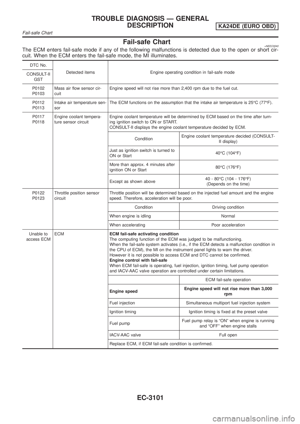
Fail-safe Chart=NEEC0040The ECM enters fail-safe mode if any of the following malfunctions is detected due to the open or short cir-
cuit. When the ECM enters the fail-safe mode, the MI illuminates.
DTC No.
Detected items Engine operating condition in fail-safe mode
CONSULT-II
GST
P0102
P0103Mass air flow sensor cir-
cuitEngine speed will not rise more than 2,400 rpm due to the fuel cut.
P0112
P0113Intake air temperature sen-
sorThe ECM functions on the assumption that the intake air temperature is 25ÉC (77ÉF).
P0117
P0118Engine coolant tempera-
ture sensor circuitEngine coolant temperature will be determined by ECM based on the time after turn-
ing ignition switch to ON or START.
CONSULT-II displays the engine coolant temperature decided by ECM.
ConditionEngine coolant temperature decided (CONSULT-
II display)
Just as ignition switch is turned to
ON or Start40ÉC (104ÉF)
More than approx. 4 minutes after
ignition ON or Start80ÉC (176ÉF)
Except as shown above40 - 80ÉC (104 - 176ÉF)
(Depends on the time)
P0122
P0123Throttle position sensor
circuitThrottle position will be determined based on the injected fuel amount and the engine
speed. Therefore, acceleration will be poor.
Condition Driving condition
When engine is idling Normal
When accelerating Poor acceleration
Unable to
access ECMECMECM fail-safe activating condition
The computing function of the ECM was judged to be malfunctioning.
When the fail-safe system activates (i.e., if the ECM detects a malfunction condition in
the CPU of ECM), the MI on the instrument panel lights to warn the driver.
However it is not possible to access ECM and DTC cannot be confirmed.
Engine control with fail-safe
When ECM fail-safe is operating, fuel injection, ignition timing, fuel pump operation
and IACV-AAC valve operation are controlled under certain limitations.
ECM fail-safe operation
Engine speedEngine speed will not rise more than 3,000
rpm
Fuel injection Simultaneous multiport fuel injection system
Ignition timing Ignition timing is fixed at the preset valve
Fuel pumpFuel pump relay is ªONº when engine is running
and ªOFFº when engine stalls
IACV-AAC valve Full open
Replace ECM, if ECM fail-safe condition is confirmed.
TROUBLE DIAGNOSIS Ð GENERAL
DESCRIPTION
KA24DE (EURO OBD)
Fail-safe Chart
EC-3101
Page 137 of 1306
![NISSAN PICK-UP 2001 Repair Manual TERMI-
NAL
NO.WIRE
COLORITEM CONDITION DATA (DC Voltage)
3 W Tachometer[Engine is running]
+Warm-up condition
+Idle speed0-1V
SEF190T
[Engine is running]
+Engine speed is 2,000 rpm0.5-2V
SEF191T
4 L/B NISSAN PICK-UP 2001 Repair Manual TERMI-
NAL
NO.WIRE
COLORITEM CONDITION DATA (DC Voltage)
3 W Tachometer[Engine is running]
+Warm-up condition
+Idle speed0-1V
SEF190T
[Engine is running]
+Engine speed is 2,000 rpm0.5-2V
SEF191T
4 L/B](/manual-img/5/57372/w960_57372-136.png)
TERMI-
NAL
NO.WIRE
COLORITEM CONDITION DATA (DC Voltage)
3 W Tachometer[Engine is running]
+Warm-up condition
+Idle speed0-1V
SEF190T
[Engine is running]
+Engine speed is 2,000 rpm0.5-2V
SEF191T
4 L/BECM relay (Self shut-
off)[Engine is running]
[Ignition switch OFF]
+For a few seconds after turning ignition switch
OFF0-1V
[Ignition switch OFF]
+More than a few seconds after turning ignition
switch OFFBATTERY VOLTAGE
(11 - 14V)
5 W/PUEVAP canister purge
volume control sole-
noid valve[Engine is running]
+Idle speedBATTERY VOLTAGE
(11 - 14V)
SEF109V
[Engine is running]
+Engine speed is 2,000 rpm (More than 200
seconds after starting engine)12 - 13V
SEF110V
TROUBLE DIAGNOSIS Ð GENERAL
DESCRIPTION
KA24DE (EURO OBD)
ECM Terminals and Reference Value
EC-3112
Page 138 of 1306
![NISSAN PICK-UP 2001 Repair Manual TERMI-
NAL
NO.WIRE
COLORITEM CONDITION DATA (DC Voltage)
9 BR/WAmbient air tempera-
ture switch[Engine is running]
+Idle speed
+Ambient air temperature is above 23ÉC (73ÉF)
+Air conditioner is opera NISSAN PICK-UP 2001 Repair Manual TERMI-
NAL
NO.WIRE
COLORITEM CONDITION DATA (DC Voltage)
9 BR/WAmbient air tempera-
ture switch[Engine is running]
+Idle speed
+Ambient air temperature is above 23ÉC (73ÉF)
+Air conditioner is opera](/manual-img/5/57372/w960_57372-137.png)
TERMI-
NAL
NO.WIRE
COLORITEM CONDITION DATA (DC Voltage)
9 BR/WAmbient air tempera-
ture switch[Engine is running]
+Idle speed
+Ambient air temperature is above 23ÉC (73ÉF)
+Air conditioner is operating0V
[Engine is running]
+Idle speed
+Ambient air temperature is above 23ÉC (73ÉF)
+Air conditioner is operatingBATTERY VOLTAGE
(11 - 14V)
[Engine is running]
+Idle speed
+Ambient air temperature is above 23ÉC (73ÉF)
+Air conditioner is not operatingApproximately 5V
10 B/P ECM ground[Engine is running]
+Idle speedEngine ground
11*1 Y Fuel pump relay[Ignition switch ON]
+For 5 seconds after turning ignition switch ON
[Engine is running]0-1V
[Ignition switch ON]
+More than 5 seconds after turning ignition
switch ONBATTERY VOLTAGE
(11 - 14V)
12 G/W Air conditioner relay[Engine is running]
+Both A/C switch and blower switch are ON*
*: Any mode except ªOFFº, ambient air tem-
perature above 10ÉC (50ÉF).Approximately 0V
[Engine is running]
+A/C switch is OFFBATTERY VOLTAGE
(11 - 14V)
14*2 Y Fuel pump relay[Ignition switch ON]
+For 5 seconds after turning ignition switch0-1V
[Ignition switch ON]
+More than 5 seconds after turning ignition
switch ONBATTERY VOLTAGE
(11 - 14V)
18 OR/B Malfunction indicator[Ignition switch ON]0-1V
[Engine is running]
+Idle speedBATTERY VOLTAGE
(11 - 14V)
19 B/P ECM ground[Engine is running]
+Idle speedEngine ground
20 R Start signal[Ignition switch ON]Approximately 0V
[Ignition switch START]BATTERY VOLTAGE
(11 - 14V)
21 YAir conditioner pres-
sure switch[Engine is running]
+Both air conditioner switch and blower switch
are ON (Compressor operates)Approximately 0V
[Engine is running]
+Air conditioner switch is OFFBATTERY VOLTAGE
(11 - 14V)
22 Y/RPark/neutral position
(PNP) switch[Ignition switch ON]
+Gear position is ªNºApproximately 0V
[Ignition switch ON]
+Except the above gear positionApproximately 5V
TROUBLE DIAGNOSIS Ð GENERAL
DESCRIPTION
KA24DE (EURO OBD)
ECM Terminals and Reference Value
EC-3113