Page 151 of 1306

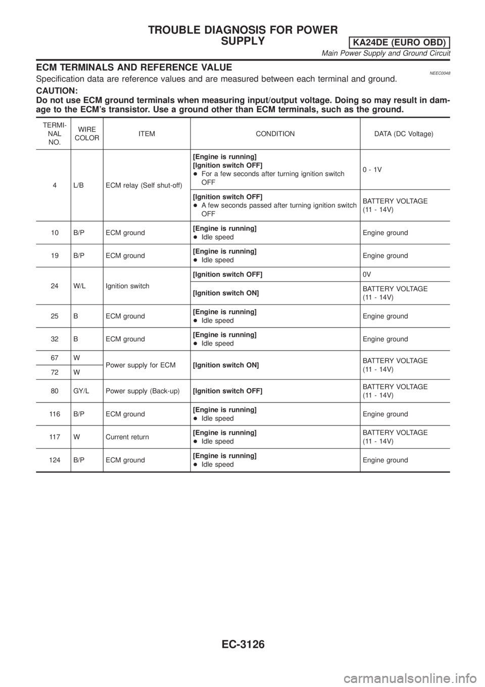
ECM TERMINALS AND REFERENCE VALUENEEC0048Specification data are reference values and are measured between each terminal and ground.
CAUTION:
Do not use ECM ground terminals when measuring input/output voltage. Doing so may result in dam-
age to the ECM's transistor. Use a ground other than ECM terminals, such as the ground.
TERMI-
NAL
NO.WIRE
COLORITEM CONDITION DATA (DC Voltage)
4 L/B ECM relay (Self shut-off)[Engine is running]
[Ignition switch OFF]
+For a few seconds after turning ignition switch
OFF0-1V
[Ignition switch OFF]
+A few seconds passed after turning ignition switch
OFFBATTERY VOLTAGE
(11 - 14V)
10 B/P ECM ground[Engine is running]
+Idle speedEngine ground
19 B/P ECM ground[Engine is running]
+Idle speedEngine ground
24 W/L Ignition switch[Ignition switch OFF]0V
[Ignition switch ON]BATTERY VOLTAGE
(11 - 14V)
25 B ECM ground[Engine is running]
+Idle speedEngine ground
32 B ECM ground[Engine is running]
+Idle speedEngine ground
67 W
Power supply for ECM[Ignition switch ON]BATTERY VOLTAGE
(11 - 14V)
72 W
80 GY/L Power supply (Back-up)[Ignition switch OFF]BATTERY VOLTAGE
(11 - 14V)
116 B/P ECM ground[Engine is running]
+Idle speedEngine ground
117 W Current return[Engine is running]
+Idle speedBATTERY VOLTAGE
(11 - 14V)
124 B/P ECM ground[Engine is running]
+Idle speedEngine ground
TROUBLE DIAGNOSIS FOR POWER
SUPPLY
KA24DE (EURO OBD)
Main Power Supply and Ground Circuit
EC-3126
Page 153 of 1306

5 CHECK POWER SUPPLY-II
1. Disconnect ECM relay.
LEC106A
2. Check voltage between ECM relay terminals 1, 3 and ground with CONSULT-II or tester.
SEC313D
Voltage: Battery voltage
OK or NG
OK©GO TO 7.
NG©GO TO 6.
6 DETECT MALFUNCTIONING PART
Check the following.
+10A fuse
+Harness for open or short between ECM relay and battery
©Repair open circuit or short to ground or short to power in harness or connectors.
7 CHECK OUTPUT SIGNAL CIRCUIT FOR OPEN AND SHORT
1. Check harness continuity between ECM terminal 4 and ECM relay terminal 2. Refer to WIRING DIAGRAM.
Continuity should exist.
2. Also check harness for short to ground and short to power.
OK or NG
OK©Go to ªIGNITION SIGNALº, EC-3361.
NG©GO TO 8.
8 DETECT MALFUNCTIONING PART
Check the following.
+Harness connectors E101, M5
+Harness for open or short between ECM relay and ECM
©Repair open circuit or short to ground or short to power in harness or connectors.
TROUBLE DIAGNOSIS FOR POWER
SUPPLY
KA24DE (EURO OBD)
Main Power Supply and Ground Circuit
EC-3128
Page 155 of 1306
12 CHECK HARNESS CONTINUITY BETWEEN ECM RELAY AND ECM
1. Disconnect ECM harness connector.
2. Disconnect ECM relay.
LEC106A
3. Check harness continuity between ECM terminals 67, 72, 117 and ECM relay terminal 7.
SEC267D
Continuity should exist.
4. Also check harness for short to ground and short to power.
OK or NG
OK©GO TO 14.
NG©GO TO 13.
13 DETECT MALFUNCTIONING PART
Check the following.
+Harness connectors E101, M5
+Harness for open or short between ECM and ECM relay
©Repair harness or connectors.
TROUBLE DIAGNOSIS FOR POWER
SUPPLY
KA24DE (EURO OBD)
Main Power Supply and Ground Circuit
EC-3130
Page 156 of 1306
14 CHECK VOLTAGE BETWEEN ECM RELAY AND GROUND
Check voltage between ECM relay terminals 1, 6 and ground with CONSULT-II or tester.
SEC268D
Voltage: Battery voltage
OK or NG
OK©GO TO 16.
NG©GO TO 15.
15 DETECT MALFUNCTIONING PART
Check the following.
+10A fuse
+Harness for open or short between ECM relay and fuse
©Repair harness or connectors.
16 CHECK OUTPUT SIGNAL CIRCUIT
1. Check harness continuity between ECM terminal 4 and ECM relay terminal 2.
SEC269D
Continuity should exist.
2. Also check harness for short to ground and short to power.
OK or NG
OK©GO TO 18.
NG©GO TO 17.
17 DETECT MALFUNCTIONING PART
Check the following.
+Harness connectors E101, M5
+Harness for open or short between ECM and ECM relay
©Repair harness or connectors.
TROUBLE DIAGNOSIS FOR POWER
SUPPLY
KA24DE (EURO OBD)
Main Power Supply and Ground Circuit
EC-3131
Page 157 of 1306
18 CHECK ECM RELAY
1. Apply 12V direct current between ECM relay terminals 1 and 2.
2. Check continuity between ECM relay terminals 6 and 7.
PBIB0077E
12V (1 - 2) applied: Continuity exists.
No voltage applied: No continuity
OK or NG
OK©GO TO 19.
NG©Replace ECM relay.
19 CHECK GROUND CIRCUIT
1. Turn ignition switch ªOFFº.
2. Disconnect ECM harness connector.
3. Check harness continuity between ECM terminals 10, 19, 25, 32, 116, 124 and engine ground.
SEF119V
Continuity should exist.
4. Also check harness for short to power.
OK or NG
OK©GO TO 20.
NG©Repair open circuit or short to power in harness or connectors.
20 CHECK INTERMITTENT INCIDENT
Perform ªTROUBLE DIAGNOSIS FOR INTERMITTENT INCIDENTº, EC-3123.
©INSPECTION END
TROUBLE DIAGNOSIS FOR POWER
SUPPLY
KA24DE (EURO OBD)
Main Power Supply and Ground Circuit
EC-3132
Page 173 of 1306
4 CHECK POWER SUPPLY
1. Disconnect mass air flow sensor harness connector.
AEC131A
2. Turn ignition switch ON.
3. Check voltage between terminal 3 and ground with CONSULT-II or tester.
AEC691
Voltage: Battery voltage
OK or NG
OK©GO TO 6.
NG©GO TO 5.
5 DETECT MALFUNCTIONING PART
Check the following.
+Harness connectors E101, M5
+Harness for open or short between ECM relay and mass air flow sensor
+Harness for open or short between mass air flow sensor and ECM
©Repair harness or connectors.
6 CHECK GROUND CIRCUIT
1. Turn ignition switch OFF.
2. Disconnect ECM harness connector.
3. Check harness continuity between mass air flow sensor terminal 2 and ECM terminal 55. Refer to wiring diagram.
Continuity should exist.
4. Also check harness for short to ground or short to power.
OK or NG
OK©GO TO 7.
NG©Repair open circuit or short to ground or short to power in harness or connectors.
DTC P0101 MAF SENSORKA24DE (EURO OBD)
Diagnostic Procedure
EC-3148
Page 181 of 1306
4 CHECK POWER SUPPLY
1. Disconnect mass air flow sensor harness connector.
AEC131A
2. Turn ignition switch ON.
3. Check voltage between terminal 3 and ground with CONSULT-II or tester.
AEC691
Voltage: Battery voltage
OK or NG
OK©GO TO 6.
NG©GO TO 5.
5 DETECT MALFUNCTIONING PART
Check the following.
+Harness connectors E101, M5
+Harness for open or short between ECM relay and mass air flow sensor
+Harness for open or short between mass air flow sensor and ECM
©Repair harness or connectors.
DTC P0102, P0103 MAF SENSORKA24DE (EURO OBD)
Diagnostic Procedure
EC-3156
Page 295 of 1306

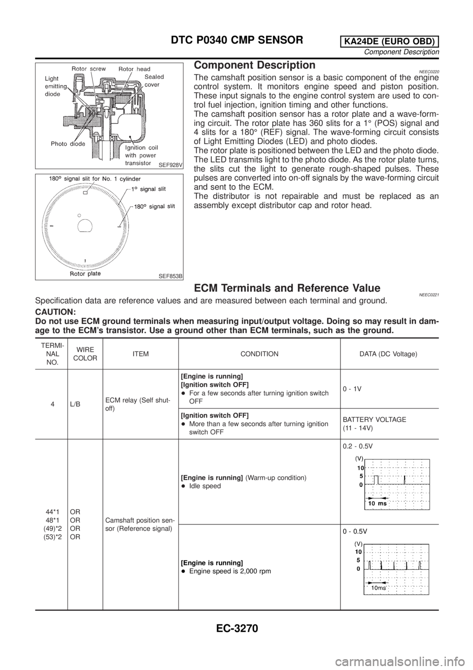
SEF928V
SEF853B
Component DescriptionNEEC0220The camshaft position sensor is a basic component of the engine
control system. It monitors engine speed and piston position.
These input signals to the engine control system are used to con-
trol fuel injection, ignition timing and other functions.
The camshaft position sensor has a rotor plate and a wave-form-
ing circuit. The rotor plate has 360 slits for a 1É (POS) signal and
4 slits for a 180É (REF) signal. The wave-forming circuit consists
of Light Emitting Diodes (LED) and photo diodes.
The rotor plate is positioned between the LED and the photo diode.
The LED transmits light to the photo diode. As the rotor plate turns,
the slits cut the light to generate rough-shaped pulses. These
pulses are converted into on-off signals by the wave-forming circuit
and sent to the ECM.
The distributor is not repairable and must be replaced as an
assembly except distributor cap and rotor head.
ECM Terminals and Reference ValueNEEC0221Specification data are reference values and are measured between each terminal and ground.
CAUTION:
Do not use ECM ground terminals when measuring input/output voltage. Doing so may result in dam-
age to the ECM's transistor. Use a ground other than ECM terminals, such as the ground.
TERMI-
NAL
NO.WIRE
COLORITEM CONDITION DATA (DC Voltage)
4 L/BECM relay (Self shut-
off)[Engine is running]
[Ignition switch OFF]
+For a few seconds after turning ignition switch
OFF0-1V
[Ignition switch OFF]
+More than a few seconds after turning ignition
switch OFFBATTERY VOLTAGE
(11 - 14V)
44*1
48*1
(49)*2
(53)*2OR
OR
OR
ORCamshaft position sen-
sor (Reference signal)[Engine is running](Warm-up condition)
+Idle speed0.2 - 0.5V
[Engine is running]
+Engine speed is 2,000 rpm0 - 0.5V
DTC P0340 CMP SENSORKA24DE (EURO OBD)
Component Description
EC-3270