Page 300 of 1306

3 CHECK POWER SUPPLY
1. Disconnect camshaft position sensor harness connector.
SEC276D
2. Turn ignition switch ON.
3. Check voltage between terminal 5 and ground with CONSULT-II or tester.
SEF040S
Voltage: Battery voltage
OK or NG
OK©GO TO 5.
NG©GO TO 4.
4 DETECT MALFUNCTIONING PART
Check the following.
+Harness connectors E101, M5
+Harness for open or short between camshaft position sensor and ECM relay
+Harness for open or short between camshaft position sensor and ECM
©Repair open circuit or short to ground or short to power in harness or connectors.
5 CHECK INPUT SIGNAL CIRCUIT
1. Turn ignition switch OFF.
2. Disconnect ECM harness connector.
3. Check harness continuity between sensor terminal 4 and ECM terminal 49 or (44)*, sensor terminal 3 and ECM termi-
nals 44, 48 or (49, 53)*. Refer to wiring diagram.
Continuity should exist.
*: Model with NATS (Nissan Anti-Theft System)
4. Also check harness for short to ground and short to power.
OK or NG
OK©GO TO 6.
NG©Repair open circuit or short to ground or short to power in harness or connectors.
DTC P0340 CMP SENSORKA24DE (EURO OBD)
Diagnostic Procedure
EC-3275
Page 309 of 1306

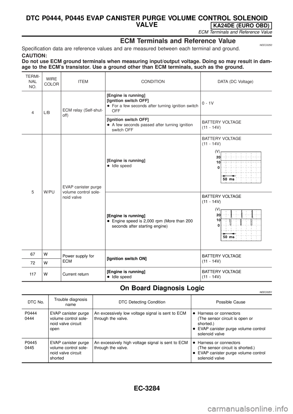
ECM Terminals and Reference ValueNEEC0250Specification data are reference values and are measured between each terminal and ground.
CAUTION:
Do not use ECM ground terminals when measuring input/output voltage. Doing so may result in dam-
age to the ECM's transistor. Use a ground other than ECM terminals, such as the ground.
TERMI-
NAL
NO.WIRE
COLORITEM CONDITION DATA (DC Voltage)
4 L/BECM relay (Self-shut-
off)[Engine is running]
[Ignition switch OFF]
+For a few seconds after turning ignition switch
OFF0-1V
[Ignition switch OFF]
+A few seconds passed after turning ignition
switch OFFBATTERY VOLTAGE
(11 - 14V)
5 W/PUEVAP canister purge
volume control sole-
noid valve[Engine is running]
+Idle speedBATTERY VOLTAGE
(11 - 14V)
[Engine is running]
+Engine speed is 2,000 rpm (More than 200
seconds after starting engine)BATTERY VOLTAGE
(11 - 14V)
67 W
Power supply for
ECM[Ignition switch ON]BATTERY VOLTAGE
(11 - 14V)
72 W
117 W Current return[Engine is running]
+Idle speedBATTERY VOLTAGE
(11 - 14V)
On Board Diagnosis LogicNEEC0251
DTC No.Trouble diagnosis
nameDTC Detecting Condition Possible Cause
P0444
0444EVAP canister purge
volume control sole-
noid valve circuit
openAn excessively low voltage signal is sent to ECM
through the valve.+Harness or connectors
(The sensor circuit is open or
shorted.)
+EVAP canister purge volume control
solenoid valve
P0445
0445EVAP canister purge
volume control sole-
noid valve circuit
shortedAn excessively high voltage signal is sent to ECM
through the valve.+Harness or connectors
(The sensor circuit is shorted.)
+EVAP canister purge volume control
solenoid valve
DTC P0444, P0445 EVAP CANISTER PURGE VOLUME CONTROL SOLENOID
VALVE
KA24DE (EURO OBD)
ECM Terminals and Reference Value
EC-3284
Page 312 of 1306

Diagnostic ProcedureNEEC0254
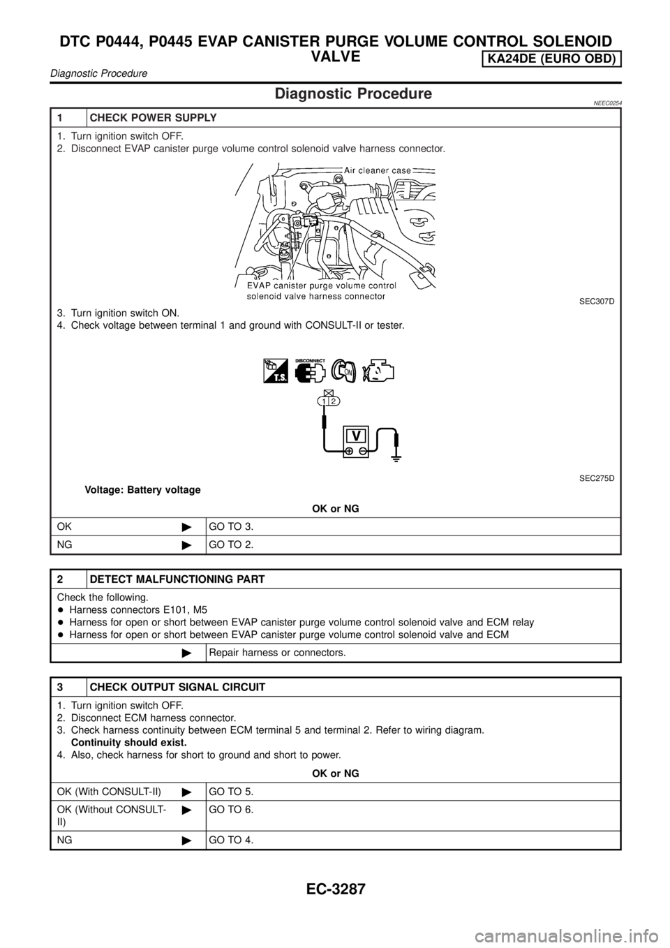
1 CHECK POWER SUPPLY
1. Turn ignition switch OFF.
2. Disconnect EVAP canister purge volume control solenoid valve harness connector.
SEC307D
3. Turn ignition switch ON.
4. Check voltage between terminal 1 and ground with CONSULT-II or tester.
SEC275D
Voltage: Battery voltage
OK or NG
OK©GO TO 3.
NG©GO TO 2.
2 DETECT MALFUNCTIONING PART
Check the following.
+Harness connectors E101, M5
+Harness for open or short between EVAP canister purge volume control solenoid valve and ECM relay
+Harness for open or short between EVAP canister purge volume control solenoid valve and ECM
©Repair harness or connectors.
3 CHECK OUTPUT SIGNAL CIRCUIT
1. Turn ignition switch OFF.
2. Disconnect ECM harness connector.
3. Check harness continuity between ECM terminal 5 and terminal 2. Refer to wiring diagram.
Continuity should exist.
4. Also, check harness for short to ground and short to power.
OK or NG
OK (With CONSULT-II)©GO TO 5.
OK (Without CONSULT-
II)©GO TO 6.
NG©GO TO 4.
DTC P0444, P0445 EVAP CANISTER PURGE VOLUME CONTROL SOLENOID
VALVE
KA24DE (EURO OBD)
Diagnostic Procedure
EC-3287
Page 391 of 1306
4 CHECK POWER SUPPLY
1. Turn ignition switch OFF.
2. Disconnect ignition coil harness connector.
SEC276D
3. Turn ignition switch ON.
4. Check voltage between terminal 7 and ground with CONSULT-II or tester.
AEC698
Voltage: Battery voltage
OK or NG
OK©GO TO 6.
NG©GO TO 5.
5 DETECT MALFUNCTIONING PART
Check the following.
+Harness connectors E101, M5
+Harness for open or short between ignition coil and ECM relay
+Harness for open or short between ECM relay and fuse
©Repair harness or connectors.
6 CHECK GROUND CIRCUIT
1. Turn ignition switch OFF.
2. Disconnect power transistor harness connector.
3. Check harness continuity between power transistor terminal 2 and engine ground. Refer to Wiring Diagram.
Continuity should exist.
4. Also check harness for short to power.
OK or NG
OK©GO TO 7.
NG©Repair open circuit or short to power in harness or connectors.
IGNITION SIGNALKA24DE (EURO OBD)
Diagnostic Procedure
EC-3366
Page 403 of 1306

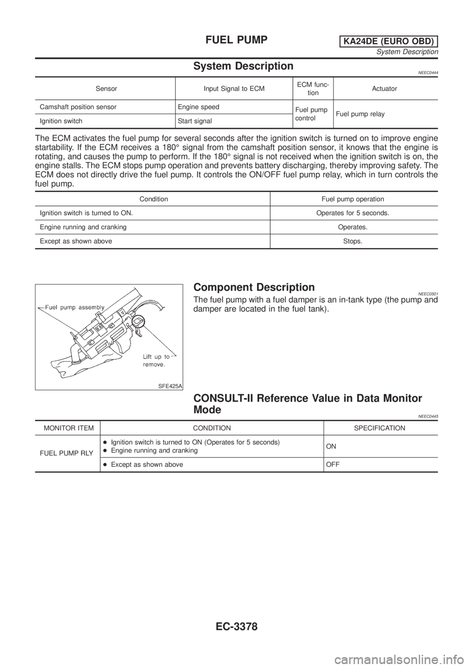
System DescriptionNEEC0444
Sensor Input Signal to ECMECM func-
tionActuator
Camshaft position sensor Engine speed
Fuel pump
controlFuel pump relay
Ignition switch Start signal
The ECM activates the fuel pump for several seconds after the ignition switch is turned on to improve engine
startability. If the ECM receives a 180É signal from the camshaft position sensor, it knows that the engine is
rotating, and causes the pump to perform. If the 180É signal is not received when the ignition switch is on, the
engine stalls. The ECM stops pump operation and prevents battery discharging, thereby improving safety. The
ECM does not directly drive the fuel pump. It controls the ON/OFF fuel pump relay, which in turn controls the
fuel pump.
Condition Fuel pump operation
Ignition switch is turned to ON. Operates for 5 seconds.
Engine running and cranking Operates.
Except as shown aboveStops.
SFE425A
Component DescriptionNEEC0501The fuel pump with a fuel damper is an in-tank type (the pump and
damper are located in the fuel tank).
CONSULT-II Reference Value in Data Monitor
Mode
NEEC0445
MONITOR ITEM CONDITION SPECIFICATION
FUEL PUMP RLY+Ignition switch is turned to ON (Operates for 5 seconds)
+Engine running and crankingON
+Except as shown above OFF
FUEL PUMPKA24DE (EURO OBD)
System Description
EC-3378
Page 404 of 1306
ECM Terminals and Reference Value=NEEC0446Specification data are reference values and are measured between each terminal and ground.
CAUTION:
Do not use ECM ground terminals when measuring input/output voltage. Doing so may result in dam-
age to the ECM's transistor. Use a ground other than ECM terminals, such as the ground.
TERMI-
NAL
NO.WIRE
COLORITEM CONDITION DATA (DC Voltage)
11*1 Y Fuel pump relay[Ignition switch ªONº]
+For 5 seconds after turning ignition switch ªONº
[Engine is running]0-1V
[Ignition switch ªONº]
+More than 5 seconds after turning ignition switch
ªONºBATTERY VOLTAGE
(11 - 14V)
14*2 Y Fuel pump relay[Ignition switch ON]
+For 5 seconds after turning ignition switch0-1V
[Ignition switch ON]
+More than 5 seconds after turning ignition switch
ONBATTERY VOLTAGE
(11 - 14V)
*1: Model without NATS (Nissan Anti-Theft System)
*2: Model with NATS (Nissan Anti-Theft System)
FUEL PUMPKA24DE (EURO OBD)
ECM Terminals and Reference Value
EC-3379
Page 406 of 1306
Diagnostic ProcedureNEEC1074
1 CHECK OVERALL FUNCTION
1. Turn ignition switch ON.
2. Pinch fuel feed hose with two fingers.
SEF348V
Fuel pressure pulsation should be felt on the fuel feed hose for 5 seconds after ignition switch is turned ªONº.
OK or NG
OK©INSPECTION END
NG©GO TO 2.
2 CHECK POWER SUPPLY
1. Turn ignition switch OFF.
2. Disconnect fuel pump relay.
LEC103A
3. Turn ignition switch ON.
4. Check voltage between terminals 2, 5 and ground with CONSULT-II or tester.
SEC279D
Voltage: Battery voltage
OK or NG
OK©GO TO 4.
NG©GO TO 3.
FUEL PUMPKA24DE (EURO OBD)
Diagnostic Procedure
EC-3381
Page 407 of 1306

3 DETECT MALFUNCTIONING PART
Check the following.
+15A fuse
+Harness for open or short between fuse and fuel pump relay
©Repair harness or connectors.
4 CHECK FUEL PUMP CIRCUIT
1. Turn ignition switch OFF.
2. Disconnect fuel level sensor unit and fuel pump harness connector.
SEF334VA
3. Check harness continuity between fuel pump terminal 4 and body ground, fuel pump terminal 2 and fuel pump relay
terminal 3. Refer to wiring diagram.
Continuity should exist.
4. Also check harness for short to ground and short to power.
OK or NG
OK©GO TO 6.
NG©GO TO 5.
5 DETECT MALFUNCTIONING PART
Check the following.
+Harness connectors M121, C9
+Harness for open or short between fuel pump and body ground
+Harness for open or short between fuel pump and fuel pump relay
©Repair open circuit or short to ground or short to power in harness or connectors.
6 CHECK OUTPUT SIGNAL CIRCUIT
1. Disconnect ECM harness connector.
2. Check harness continuity between ECM terminal 11 or (14)* and fuel pump relay terminal 1. Refer to wiring diagram.
*: Model with NATS (Nissan Anti-Theft System)
Continuity should exist.
3. Also check harness for short to ground and short to power.
OK or NG
OK©GO TO 8.
NG©Repair open circuit or short to ground or short to power in harness or connectors.
FUEL PUMPKA24DE (EURO OBD)
Diagnostic Procedure
EC-3382