Page 553 of 1306
15 CHECK ACCELERATOR POSITION SWITCH POWER SUPPLY CIRCUIT
1. Turn ignition switch ªOFFº.
2. Disconnect accelerator work unit harness connector.
SEC233D
3. Turn ignition switch ªONº.
4. Check voltage between accelerator position switch terminal 5 and ground with CONSULT-II or tester.
SEC243D
OK or NG
OKcGO TO 17.
NGcGO TO 16.
16 DETECT MALFUNCTIONING PART
Check the following.
+Harness connectors E101, M5
+Harness connectors M47, F55 (RHD models)
+Harness for open or short between accelerator work unit and ECM relay
+Harness for open or short between accelerator work unit and ECM
cRepair harness or connectors.
DTC 0403 ACCEL POS SENSORYD25DDTi
Diagnostic Procedure (Cont'd)
EC-3528
Page 572 of 1306
Diagnostic Procedure
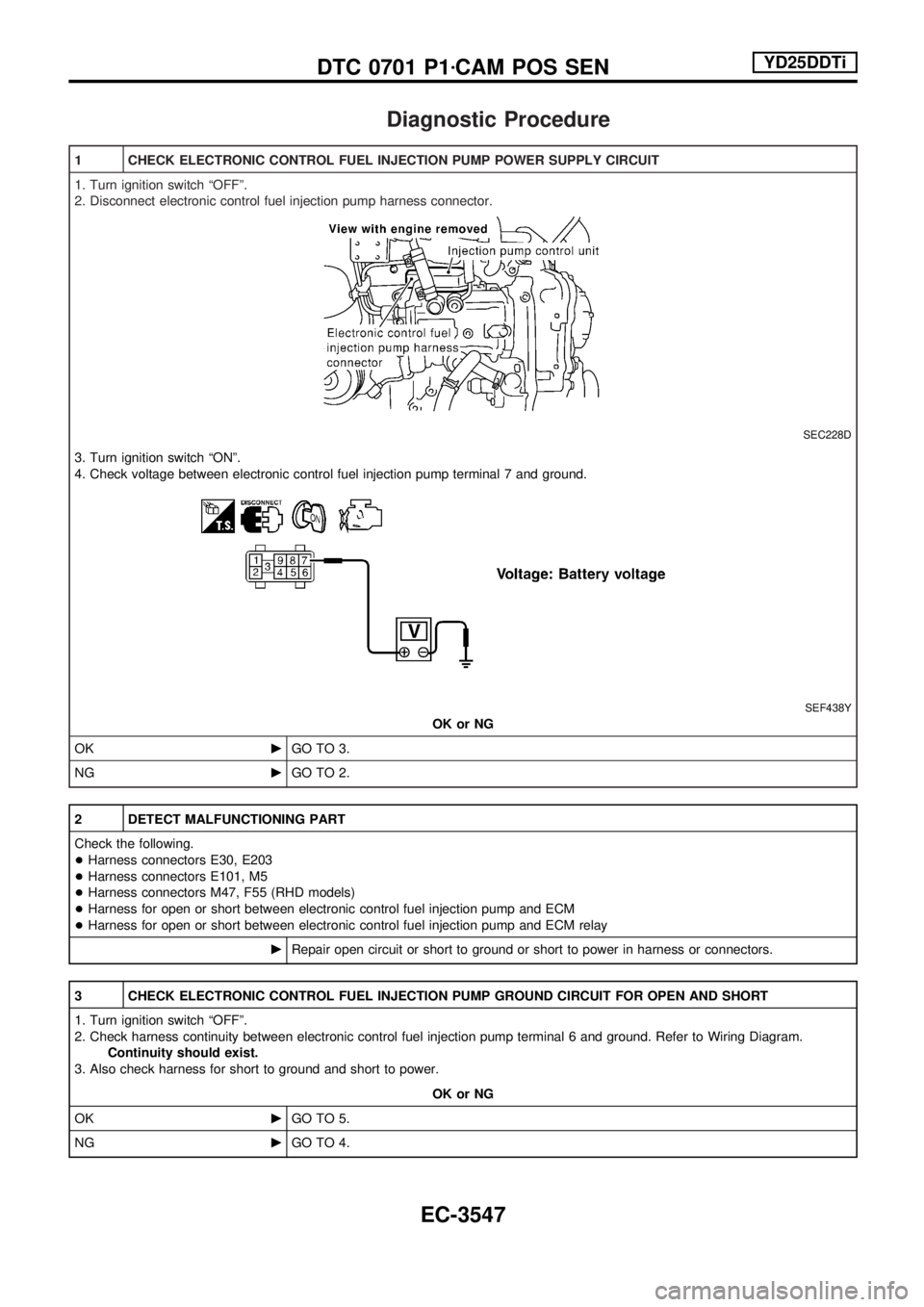
1 CHECK ELECTRONIC CONTROL FUEL INJECTION PUMP POWER SUPPLY CIRCUIT
1. Turn ignition switch ªOFFº.
2. Disconnect electronic control fuel injection pump harness connector.
SEC228D
3. Turn ignition switch ªONº.
4. Check voltage between electronic control fuel injection pump terminal 7 and ground.
SEF438Y
OK or NG
OKcGO TO 3.
NGcGO TO 2.
2 DETECT MALFUNCTIONING PART
Check the following.
+Harness connectors E30, E203
+Harness connectors E101, M5
+Harness connectors M47, F55 (RHD models)
+Harness for open or short between electronic control fuel injection pump and ECM
+Harness for open or short between electronic control fuel injection pump and ECM relay
cRepair open circuit or short to ground or short to power in harness or connectors.
3 CHECK ELECTRONIC CONTROL FUEL INJECTION PUMP GROUND CIRCUIT FOR OPEN AND SHORT
1. Turn ignition switch ªOFFº.
2. Check harness continuity between electronic control fuel injection pump terminal 6 and ground. Refer to Wiring Diagram.
Continuity should exist.
3. Also check harness for short to ground and short to power.
OK or NG
OKcGO TO 5.
NGcGO TO 4.
DTC 0701 P1zCAM POS SENYD25DDTi
EC-3547
Page 579 of 1306
Diagnostic Procedure
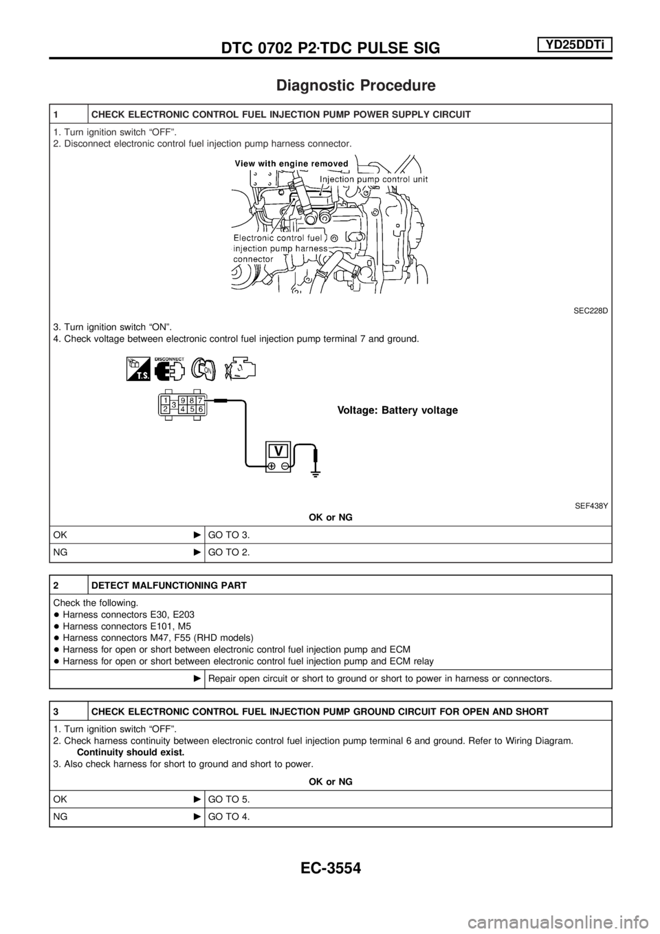
1 CHECK ELECTRONIC CONTROL FUEL INJECTION PUMP POWER SUPPLY CIRCUIT
1. Turn ignition switch ªOFFº.
2. Disconnect electronic control fuel injection pump harness connector.
SEC228D
3. Turn ignition switch ªONº.
4. Check voltage between electronic control fuel injection pump terminal 7 and ground.
SEF438Y
OK or NG
OKcGO TO 3.
NGcGO TO 2.
2 DETECT MALFUNCTIONING PART
Check the following.
+Harness connectors E30, E203
+Harness connectors E101, M5
+Harness connectors M47, F55 (RHD models)
+Harness for open or short between electronic control fuel injection pump and ECM
+Harness for open or short between electronic control fuel injection pump and ECM relay
cRepair open circuit or short to ground or short to power in harness or connectors.
3 CHECK ELECTRONIC CONTROL FUEL INJECTION PUMP GROUND CIRCUIT FOR OPEN AND SHORT
1. Turn ignition switch ªOFFº.
2. Check harness continuity between electronic control fuel injection pump terminal 6 and ground. Refer to Wiring Diagram.
Continuity should exist.
3. Also check harness for short to ground and short to power.
OK or NG
OKcGO TO 5.
NGcGO TO 4.
DTC 0702 P2zTDC PULSE SIGYD25DDTi
EC-3554
Page 586 of 1306
Diagnostic Procedure
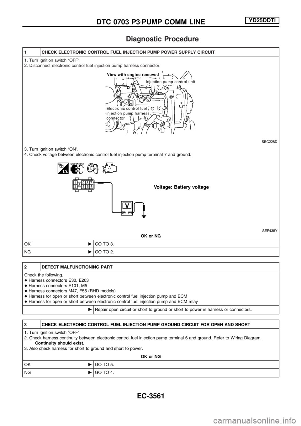
1 CHECK ELECTRONIC CONTROL FUEL INJECTION PUMP POWER SUPPLY CIRCUIT
1. Turn ignition switch ªOFFº.
2. Disconnect electronic control fuel injection pump harness connector.
SEC228D
3. Turn ignition switch ªONº.
4. Check voltage between electronic control fuel injection pump terminal 7 and ground.
SEF438Y
OK or NG
OKcGO TO 3.
NGcGO TO 2.
2 DETECT MALFUNCTIONING PART
Check the following.
+Harness connectors E30, E203
+Harness connectors E101, M5
+Harness connectors M47, F55 (RHD models)
+Harness for open or short between electronic control fuel injection pump and ECM
+Harness for open or short between electronic control fuel injection pump and ECM relay
cRepair open circuit or short to ground or short to power in harness or connectors.
3 CHECK ELECTRONIC CONTROL FUEL INJECTION PUMP GROUND CIRCUIT FOR OPEN AND SHORT
1. Turn ignition switch ªOFFº.
2. Check harness continuity between electronic control fuel injection pump terminal 6 and ground. Refer to Wiring Diagram.
Continuity should exist.
3. Also check harness for short to ground and short to power.
OK or NG
OKcGO TO 5.
NGcGO TO 4.
DTC 0703 P3zPUMP COMM LINEYD25DDTi
EC-3561
Page 593 of 1306
Diagnostic Procedure
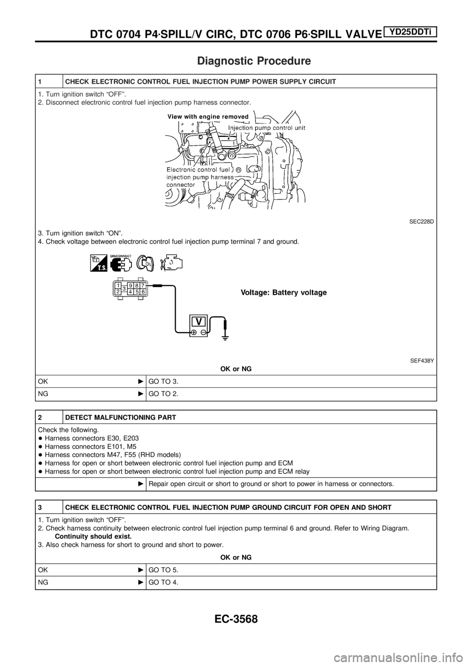
1 CHECK ELECTRONIC CONTROL FUEL INJECTION PUMP POWER SUPPLY CIRCUIT
1. Turn ignition switch ªOFFº.
2. Disconnect electronic control fuel injection pump harness connector.
SEC228D
3. Turn ignition switch ªONº.
4. Check voltage between electronic control fuel injection pump terminal 7 and ground.
SEF438Y
OK or NG
OKcGO TO 3.
NGcGO TO 2.
2 DETECT MALFUNCTIONING PART
Check the following.
+Harness connectors E30, E203
+Harness connectors E101, M5
+Harness connectors M47, F55 (RHD models)
+Harness for open or short between electronic control fuel injection pump and ECM
+Harness for open or short between electronic control fuel injection pump and ECM relay
cRepair open circuit or short to ground or short to power in harness or connectors.
3 CHECK ELECTRONIC CONTROL FUEL INJECTION PUMP GROUND CIRCUIT FOR OPEN AND SHORT
1. Turn ignition switch ªOFFº.
2. Check harness continuity between electronic control fuel injection pump terminal 6 and ground. Refer to Wiring Diagram.
Continuity should exist.
3. Also check harness for short to ground and short to power.
OK or NG
OKcGO TO 5.
NGcGO TO 4.
DTC 0704 P4zSPILL/V CIRC, DTC 0706 P6zSPILL VALVEYD25DDTi
EC-3568
Page 604 of 1306
4 DETECT MALFUNCTIONING PART
Check the following.
+Harness connectors E30, E203
+Harness connectors E101, M5
+Harness connectors M47, F55 (RHD models)
+Harness for open or short between electronic control fuel injection pump and ECM
+Harness for open or short between electronic control fuel injection pump and ECM relay
cRepair open circuit or short to ground or short to power in harness or connectors.
5 CHECK ELECTRONIC CONTROL FUEL INJECTION PUMP GROUND CIRCUIT FOR OPEN AND SHORT
1. Turn ignition switch ªOFFº.
2. Check harness continuity between electronic control fuel injection pump terminal 6 and ground. Refer to Wiring Diagram.
Continuity should exist.
3. Also check harness for short to ground and short to power.
OK or NG
OKcGO TO 7.
NGcGO TO 6.
6 DETECT MALFUNCTIONING PART
Check the following.
+Harness connectors E236, M278 (LHD models)
+Harness connectors E236, F35 (RHD models)
+Harness for open or short between electronic control fuel injection pump and engine ground
cRepair open circuit or short to ground or short to power in harness or connectors.
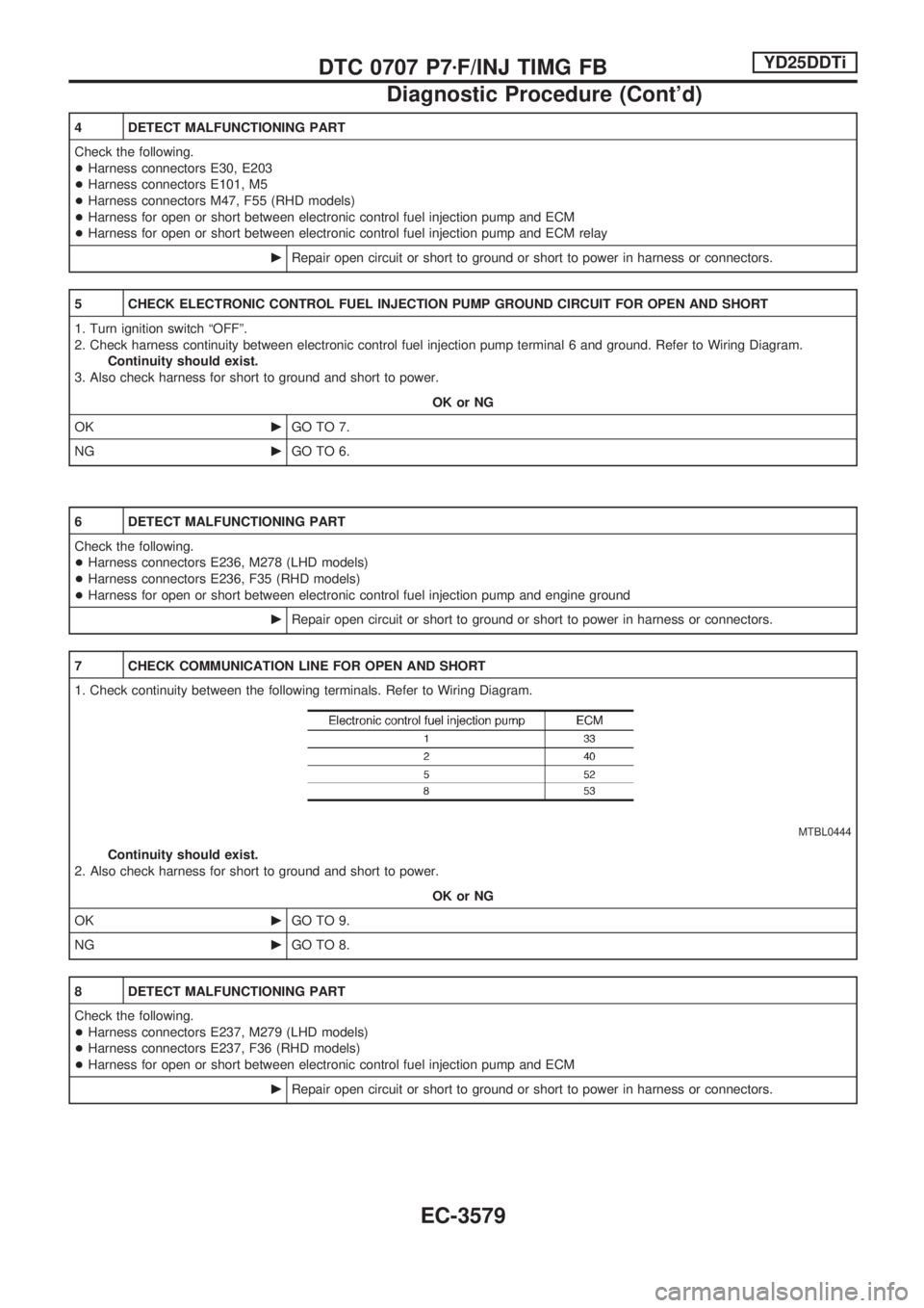
7 CHECK COMMUNICATION LINE FOR OPEN AND SHORT
1. Check continuity between the following terminals. Refer to Wiring Diagram.
MTBL0444
Continuity should exist.
2. Also check harness for short to ground and short to power.
OK or NG
OKcGO TO 9.
NGcGO TO 8.
8 DETECT MALFUNCTIONING PART
Check the following.
+Harness connectors E237, M279 (LHD models)
+Harness connectors E237, F36 (RHD models)
+Harness for open or short between electronic control fuel injection pump and ECM
cRepair open circuit or short to ground or short to power in harness or connectors.
DTC 0707 P7zF/INJ TIMG FBYD25DDTi
Diagnostic Procedure (Cont'd)
EC-3579
Page 618 of 1306
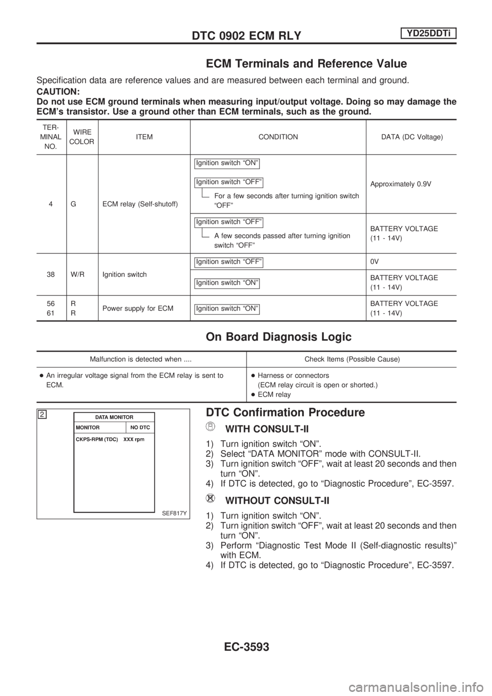
ECM Terminals and Reference Value
Specification data are reference values and are measured between each terminal and ground.
CAUTION:
Do not use ECM ground terminals when measuring input/output voltage. Doing so may damage the
ECM's transistor. Use a ground other than ECM terminals, such as the ground.
TER-
MINAL
NO.WIRE
COLORITEM CONDITION DATA (DC Voltage)
4 G ECM relay (Self-shutoff)Ignition switch ªONº
Ignition switch ªOFFº
For a few seconds after turning ignition switch
ªOFFºApproximately 0.9V
Ignition switch ªOFFº
A few seconds passed after turning ignition
switch ªOFFºBATTERY VOLTAGE
(11 - 14V)
38 W/R Ignition switchIgnition switch ªOFFº
0V
Ignition switch ªONº
BATTERY VOLTAGE
(11 - 14V)
56
61R
RPower supply for ECM Ignition switch ªONº
BATTERY VOLTAGE
(11 - 14V)
On Board Diagnosis Logic
Malfunction is detected when .... Check Items (Possible Cause)
+An irregular voltage signal from the ECM relay is sent to
ECM.+Harness or connectors
(ECM relay circuit is open or shorted.)
+ECM relay
DTC Confirmation Procedure
WITH CONSULT-II
1) Turn ignition switch ªONº.
2) Select ªDATA MONITORº mode with CONSULT-II.
3) Turn ignition switch ªOFFº, wait at least 20 seconds and then
turn ªONº.
4) If DTC is detected, go to ªDiagnostic Procedureº, EC-3597.
WITHOUT CONSULT-II
1) Turn ignition switch ªONº.
2) Turn ignition switch ªOFFº, wait at least 20 seconds and then
turn ªONº.
3) Perform ªDiagnostic Test Mode II (Self-diagnostic results)º
with ECM.
4) If DTC is detected, go to ªDiagnostic Procedureº, EC-3597.SEF817Y
DTC 0902 ECM RLYYD25DDTi
EC-3593
Page 621 of 1306
Diagnostic Procedure
1 CHECK ECM POWER SUPPLY CIRCUIT
1. Turn ignition switch ªOFFº.
2. Disconnect ECM relay.
SEC950C
3. Check voltage between ECM terminals 2, 7 and ground with CONSULT-II or tester.
SEC241D
OK or NG
OKcGO TO 3.
NGcGO TO 2.
2 DETECT MALFUNCTIONING PART
Check the following.
+20A fuse
+Harness for open and short between ECM relay and battery
cRepair open circuit or short to ground or short to power in harness or connectors.
3 CHECK ECM INPUT SIGNAL CIRCUIT FOR OPEN AND SHORT
1. Turn ignition switch ªOFFº.
2. Disconnect ECM harness connector.
3. Check harness continuity between ECM terminals 56, 61 and ECM relay terminal 6. Refer to Wiring Diagram.
Continuity should exist.
4. Also check harness for short to ground and short to power.
OK or NG
OKcGO TO 5.
NGcGO TO 4.
DTC 0902 ECM RLYYD25DDTi
EC-3596