2001 NISSAN PICK-UP air bleeding
[x] Cancel search: air bleedingPage 30 of 1306
Fuel Pump........................................................ 3398
IACV-AAC Valve .............................................. 3398
Injector ............................................................. 3398
Throttle Position Sensor .................................. 3399
Heated Oxygen Sensor 1 Heater .................... 3399
Calculated Load Value..................................... 3399
Intake Air Temperature Sensor ....................... 3399
Heated Oxygen Sensor 2 Heater .................... 3399
Crankshaft Position Sensor (OBD) .................. 3399
YD25DDTi
TROUBLE DIAGNOSIS - INDEX........................ 3400
Alphabetical & Numerical Index for DTC......... 3400
PRECAUTIONS................................................... 3402
Precautions ...................................................... 3402
ENGINE AND EMISSION CONTROL OVERALL
SYSTEM............................................................... 3405
Engine Control Component Parts Location ..... 3405
Circuit Diagram ................................................ 3408
System Diagram .............................................. 3409
System Chart ................................................... 3410
ENGINE AND EMISSION BASIC CONTROL
SYSTEM DESCRIPTION..................................... 3411
Fuel Injection Control System.......................... 3411
Fuel Injection Timing Control System.............. 3413
Air Conditioning Cut Control ............................ 3413
Fuel Cut Control (at no load & high engine
speed) .............................................................. 3413
Crankcase Ventilation System ......................... 3414
BASIC SERVICE PROCEDURE......................... 3415
Injection Tube and Injection Nozzle ................ 3415
Electronic Control Fuel Injection Pump ........... 3419
Air Bleeding...................................................... 3426
Water Draining ................................................. 3426
Accelerator Position Sensor Idle Position
Learning ........................................................... 3427
ON BOARD DIAGNOSTIC SYSTEM
DESCRIPTION..................................................... 3428
DTC and MIL Detection Logic ......................... 3428
Diagnostic Trouble Code (DTC) ...................... 3428
Malfunction Indicator Lamp (MIL) .................... 3429
CONSULT-II ..................................................... 3434
TROUBLE DIAGNOSIS - INTRODUCTION........ 3440
Introduction ...................................................... 3440
Work Flow ........................................................ 3442
TROUBLE DIAGNOSIS - BASIC INSPECTION. 3444
Basic Inspection ............................................... 3444
TROUBLE DIAGNOSIS - GENERAL
DESCRIPTION..................................................... 3450
Symptom Matrix Chart ..................................... 3450
CONSULT-II Reference Value in Data Monitor
Mode ................................................................ 3460Major Sensor Reference Graph in Data
Monitor Mode ................................................... 3462
ECM Terminals and Reference Value ............. 3463
TROUBLE DIAGNOSIS FOR INTERMITTENT
INCIDENT............................................................. 3469
Description ....................................................... 3469
Diagnostic Procedure....................................... 3469
TROUBLE DIAGNOSIS FOR POWER SUPPLY3470
Main Power Supply and Ground Circuit .......... 3470
DTC 0103 COOLANT TEMP SEN...................... 3480
Description ....................................................... 3480
On Board Diagnosis Logic ............................... 3480
DTC Confirmation Procedure .......................... 3480
Wiring Diagram ................................................ 3481
Diagnostic Procedure....................................... 3482
DTC 0104 VEHICLE SPEED SEN...................... 3484
Description ....................................................... 3484
ECM Terminals and Reference Value ............. 3484
On Board Diagnosis Logic ............................... 3484
Overall Function Check ................................... 3485
Wiring Diagram ................................................ 3486
Diagnostic Procedure....................................... 3488
DTC 0208 OVER HEAT....................................... 3489
Description ....................................................... 3489
CONSULT-II Reference Value in Data Monitor
Mode ................................................................ 3489
ECM Terminals and Reference Value ............. 3490
On Board Diagnosis Logic ............................... 3490
Overall Function Check ................................... 3491
Wiring Diagram ................................................ 3492
Diagnostic Procedure....................................... 3493
Main 12 Causes of Overheating ...................... 3500
DTC 0301 ECM 2, DTC 901 ECM 12................. 3501
Description ....................................................... 3501
On Board Diagnosis Logic ............................... 3501
DTC Confirmation Procedure .......................... 3501
Diagnostic Procedure....................................... 3502
DTC 0401 INTAKE AIR TEMPERATURE
SENSOR.............................................................. 3503
Component Description ................................... 3503
On Board Diagnosis Logic ............................... 3503
DTC Confirmation Procedure .......................... 3503
Wiring Diagram ................................................ 3505
Diagnostic Procedure....................................... 3506
DTC 0402 P9zFUEL TEMP SEN......................... 3508
Description ....................................................... 3508
CONSULT-II Reference Value in Data Monitor
Mode ................................................................ 3509
ECM Terminals and Reference Value ............. 3509
On Board Diagnosis Logic ............................... 3510
DTC Confirmation Procedure .......................... 3510
Wiring Diagram ................................................ 3511
Diagnostic Procedure....................................... 3513
EC-3005
Page 443 of 1306
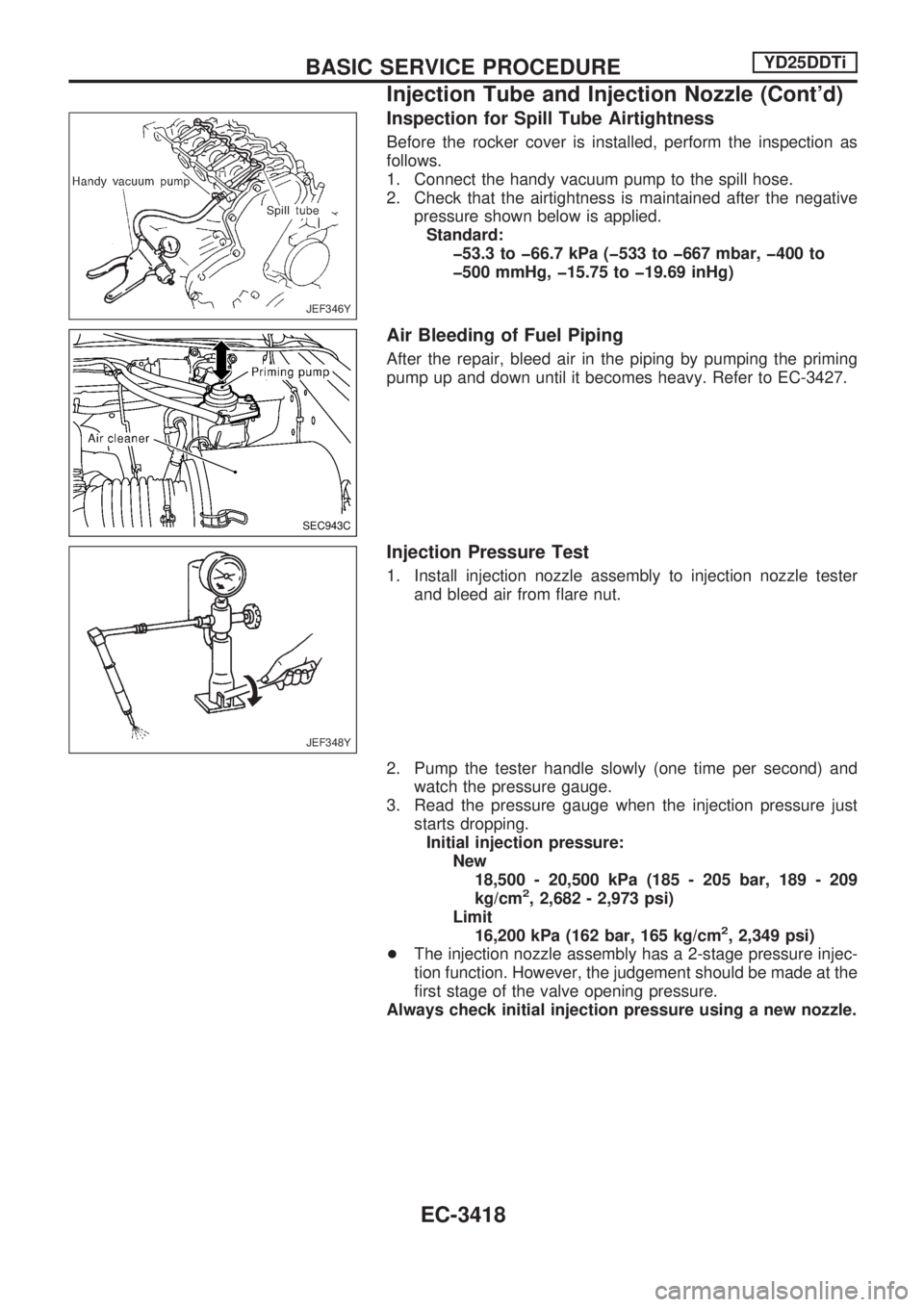
Inspection for Spill Tube Airtightness
Before the rocker cover is installed, perform the inspection as
follows.
1. Connect the handy vacuum pump to the spill hose.
2. Check that the airtightness is maintained after the negative
pressure shown below is applied.
Standard:
þ53.3 to þ66.7 kPa (þ533 to þ667 mbar, þ400 to
þ500 mmHg, þ15.75 to þ19.69 inHg)
Air Bleeding of Fuel Piping
After the repair, bleed air in the piping by pumping the priming
pump up and down until it becomes heavy. Refer to EC-3427.
Injection Pressure Test
1. Install injection nozzle assembly to injection nozzle tester
and bleed air from flare nut.
2. Pump the tester handle slowly (one time per second) and
watch the pressure gauge.
3. Read the pressure gauge when the injection pressure just
starts dropping.
Initial injection pressure:
New
18,500 - 20,500 kPa (185 - 205 bar, 189 - 209
kg/cm
2, 2,682 - 2,973 psi)
Limit
16,200 kPa (162 bar, 165 kg/cm
2, 2,349 psi)
+The injection nozzle assembly has a 2-stage pressure injec-
tion function. However, the judgement should be made at the
first stage of the valve opening pressure.
Always check initial injection pressure using a new nozzle.
JEF346Y
SEC943C
JEF348Y
BASIC SERVICE PROCEDUREYD25DDTi
Injection Tube and Injection Nozzle (Cont'd)
EC-3418
Page 451 of 1306
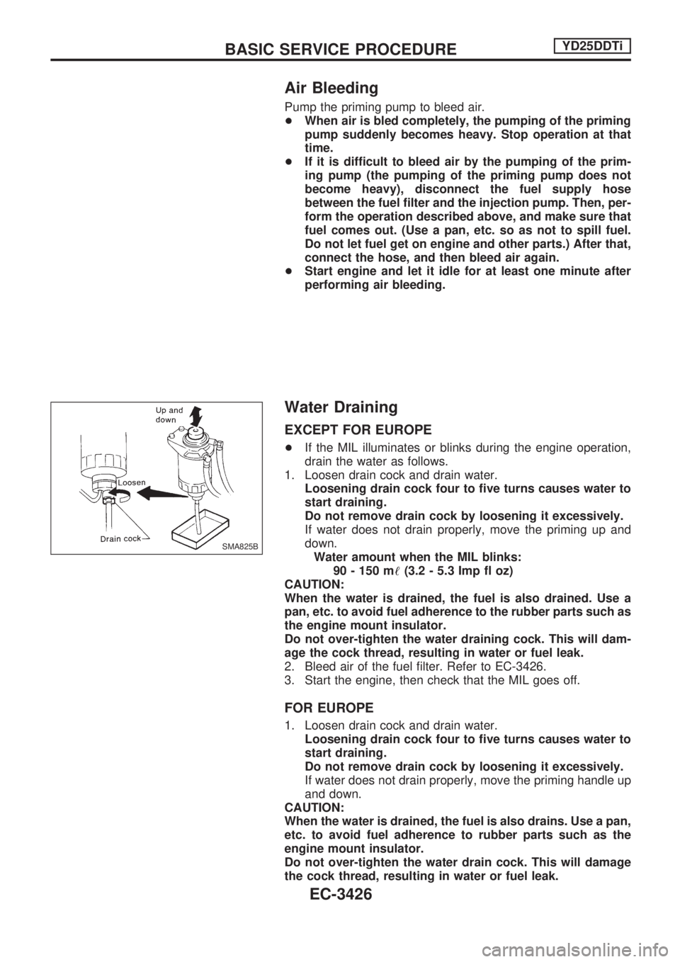
Air Bleeding
Pump the priming pump to bleed air.
+When air is bled completely, the pumping of the priming
pump suddenly becomes heavy. Stop operation at that
time.
+If it is difficult to bleed air by the pumping of the prim-
ing pump (the pumping of the priming pump does not
become heavy), disconnect the fuel supply hose
between the fuel filter and the injection pump. Then, per-
form the operation described above, and make sure that
fuel comes out. (Use a pan, etc. so as not to spill fuel.
Do not let fuel get on engine and other parts.) After that,
connect the hose, and then bleed air again.
+Start engine and let it idle for at least one minute after
performing air bleeding.
Water Draining
EXCEPT FOR EUROPE
+If the MIL illuminates or blinks during the engine operation,
drain the water as follows.
1. Loosen drain cock and drain water.
Loosening drain cock four to five turns causes water to
start draining.
Do not remove drain cock by loosening it excessively.
If water does not drain properly, move the priming up and
down.
Water amount when the MIL blinks:
90 - 150 m!(3.2 - 5.3 Imp fl oz)
CAUTION:
When the water is drained, the fuel is also drained. Use a
pan, etc. to avoid fuel adherence to the rubber parts such as
the engine mount insulator.
Do not over-tighten the water draining cock. This will dam-
age the cock thread, resulting in water or fuel leak.
2. Bleed air of the fuel filter. Refer to EC-3426.
3. Start the engine, then check that the MIL goes off.
FOR EUROPE
1. Loosen drain cock and drain water.
Loosening drain cock four to five turns causes water to
start draining.
Do not remove drain cock by loosening it excessively.
If water does not drain properly, move the priming handle up
and down.
CAUTION:
When the water is drained, the fuel is also drains. Use a pan,
etc. to avoid fuel adherence to rubber parts such as the
engine mount insulator.
Do not over-tighten the water drain cock. This will damage
the cock thread, resulting in water or fuel leak.
SMA825B
BASIC SERVICE PROCEDUREYD25DDTi
EC-3426
Page 470 of 1306
3 CHECK IDLE SPEED
With CONSULT-II
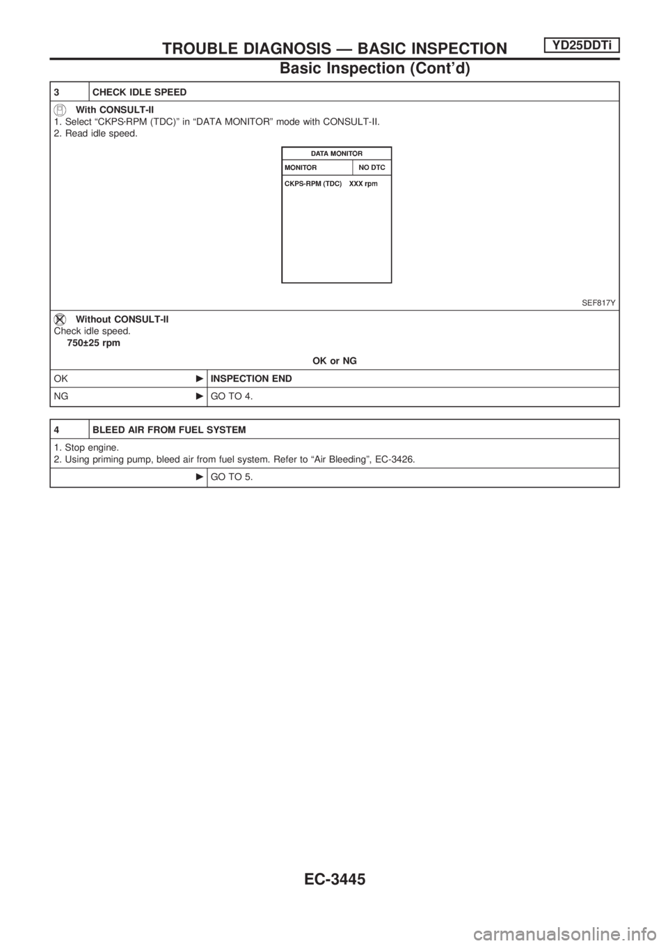
1. Select ªCKPSzRPM (TDC)º in ªDATA MONITORº mode with CONSULT-II.
2. Read idle speed.
SEF817Y
Without CONSULT-II
Check idle speed.
750 25 rpm
OK or NG
OKcINSPECTION END
NGcGO TO 4.
4 BLEED AIR FROM FUEL SYSTEM
1. Stop engine.
2. Using priming pump, bleed air from fuel system. Refer to ªAir Bleedingº, EC-3426.
cGO TO 5.
TROUBLE DIAGNOSIS Ð BASIC INSPECTIONYD25DDTi
Basic Inspection (Cont'd)
EC-3445
Page 603 of 1306
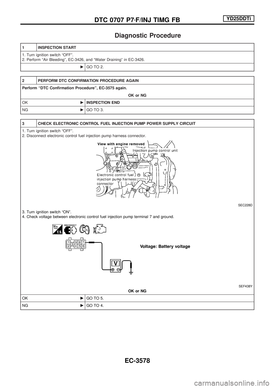
Diagnostic Procedure
1 INSPECTION START
1. Turn ignition switch ªOFFº.
2. Perform ªAir Bleedingº, EC-3426, and ªWater Drainingº in EC-3426.
cGO TO 2.
2 PERFORM DTC CONFIRMATION PROCEDURE AGAIN
Perform ªDTC Confirmation Procedureº, EC-3575 again.
OK or NG
OKcINSPECTION END
NGcGO TO 3.
3 CHECK ELECTRONIC CONTROL FUEL INJECTION PUMP POWER SUPPLY CIRCUIT
1. Turn ignition switch ªOFFº.
2. Disconnect electronic control fuel injection pump harness connector.
SEC228D
3. Turn ignition switch ªONº.
4. Check voltage between electronic control fuel injection pump terminal 7 and ground.
SEF438Y
OK or NG
OKcGO TO 5.
NGcGO TO 4.
DTC 0707 P7zF/INJ TIMG FBYD25DDTi
EC-3578
Page 913 of 1306
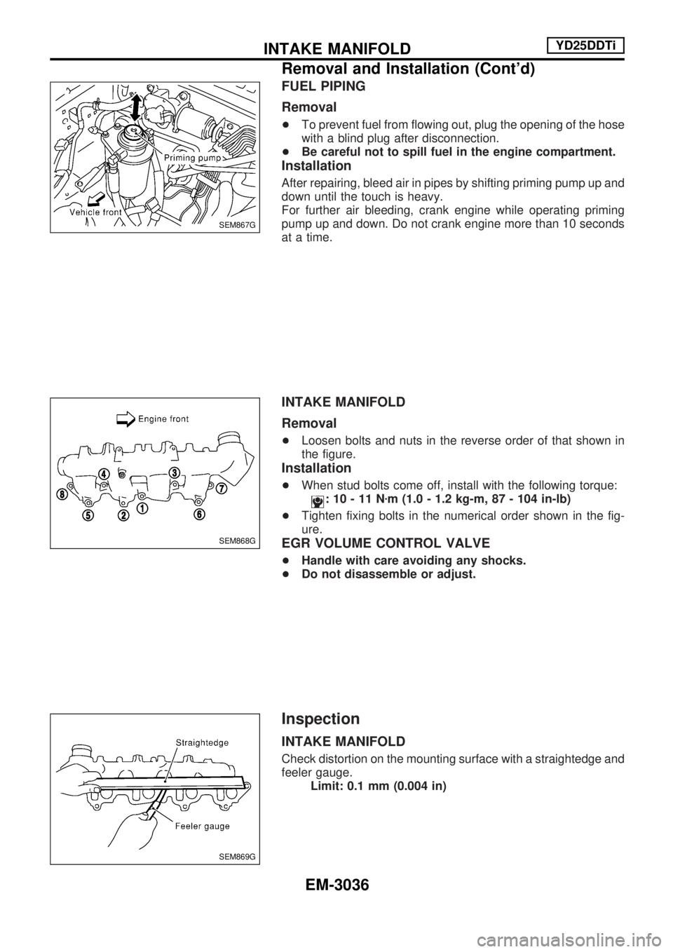
FUEL PIPING
Removal
+To prevent fuel from flowing out, plug the opening of the hose
with a blind plug after disconnection.
+Be careful not to spill fuel in the engine compartment.
Installation
After repairing, bleed air in pipes by shifting priming pump up and
down until the touch is heavy.
For further air bleeding, crank engine while operating priming
pump up and down. Do not crank engine more than 10 seconds
at a time.
INTAKE MANIFOLD
Removal
+Loosen bolts and nuts in the reverse order of that shown in
the figure.
Installation
+When stud bolts come off, install with the following torque:
:10-11Nzm (1.0 - 1.2 kg-m, 87 - 104 in-lb)
+Tighten fixing bolts in the numerical order shown in the fig-
ure.
EGR VOLUME CONTROL VALVE
+Handle with care avoiding any shocks.
+Do not disassemble or adjust.
Inspection
INTAKE MANIFOLD
Check distortion on the mounting surface with a straightedge and
feeler gauge.
Limit: 0.1 mm (0.004 in)
SEM867G
SEM868G
SEM869G
INTAKE MANIFOLDYD25DDTi
Removal and Installation (Cont'd)
EM-3036
Page 1040 of 1306
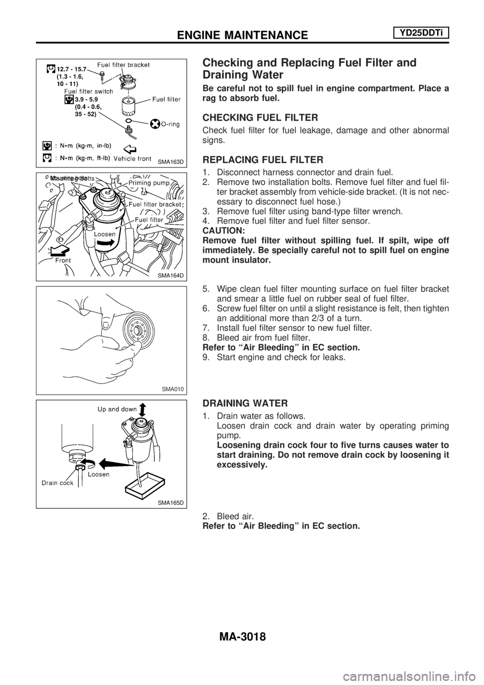
Checking and Replacing Fuel Filter and
Draining Water
Be careful not to spill fuel in engine compartment. Place a
rag to absorb fuel.
CHECKING FUEL FILTER
Check fuel filter for fuel leakage, damage and other abnormal
signs.
REPLACING FUEL FILTER
1. Disconnect harness connector and drain fuel.
2. Remove two installation bolts. Remove fuel filter and fuel fil-
ter bracket assembly from vehicle-side bracket. (It is not nec-
essary to disconnect fuel hose.)
3. Remove fuel filter using band-type filter wrench.
4. Remove fuel filter and fuel filter sensor.
CAUTION:
Remove fuel filter without spilling fuel. If spilt, wipe off
immediately. Be specially careful not to spill fuel on engine
mount insulator.
5. Wipe clean fuel filter mounting surface on fuel filter bracket
and smear a little fuel on rubber seal of fuel filter.
6. Screw fuel filter on until a slight resistance is felt, then tighten
an additional more than 2/3 of a turn.
7. Install fuel filter sensor to new fuel filter.
8. Bleed air from fuel filter.
Refer to ªAir Bleedingº in EC section.
9. Start engine and check for leaks.
DRAINING WATER
1. Drain water as follows.
Loosen drain cock and drain water by operating priming
pump.
Loosening drain cock four to five turns causes water to
start draining. Do not remove drain cock by loosening it
excessively.
2. Bleed air.
Refer to ªAir Bleedingº in EC section.
SMA163D
SMA164D Mounting bolts
SMA010
SMA165D
ENGINE MAINTENANCEYD25DDTi
MA-3018