2001 NISSAN PICK-UP alternator belt
[x] Cancel search: alternator beltPage 941 of 1306
Removal
Preparation
1. Drain coolant from radiator drain plugs.
2. Remove the following parts.
+Engine hood
+Charge air cooler
+Under protector
+Battery
+Radiator shroud
+Radiator
+Accessory belt
+Cooling fan
+Exhaust front tube
Engine room (Left)
3. Remove air duct and air cleaner case.
4. Disconnect harness connectors from alternator and air con-
ditioner compressor.
5. Remove alternator.
6. Remove installation bolts. Relocate air conditioner compres-
sor. Use a rope to temporarily anchor it to vehicle side.
7. Disconnect and relocate heating hose, install blank cap to
hose to prevent coolant from leaking.
8. Remove heat insulator.
Engine room (Right)
9. Remove fuel feed and return hoses.
CAUTION:
Install blank caps immediately to avoid fuel leakage.
10. Remove all harness connectors on the engine, and move
harnesses to the side of the vehicle.
Vehicle underfloor
11. Remove starter motor.
12. Remove front propeller shaft.
13. Remove front final drive together with differential mounting
member. Refer to PD section (ªRemoval and Installationº,
ªFront final driveº) Ð 4WD models only.
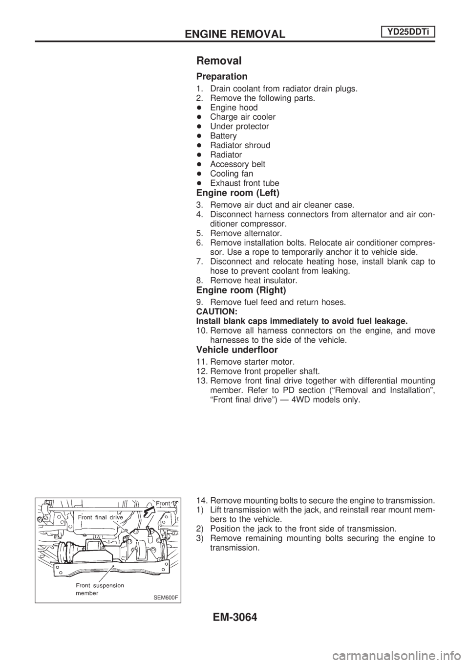
14. Remove mounting bolts to secure the engine to transmission.
1) Lift transmission with the jack, and reinstall rear mount mem-
bers to the vehicle.
2) Position the jack to the front side of transmission.
3) Remove remaining mounting bolts securing the engine to
transmission.
SEM600F
ENGINE REMOVALYD25DDTi
EM-3064
Page 1033 of 1306
Checking Tightening Torque
Checking should be performed while engine is cold.
MANIFOLD BOLTS AND NUTS
Intake
: 19.7 - 23.5 Nzm (2.0 - 2.3 kg-m, 15 - 17 ft-lb)
Exhaust
: 28.5 - 33.3 Nzm (2.9 - 3.3 kg-m, 21 - 24 ft-lb)
EXHAUST TUBE NUTS
: 41 - 48.0 Nzm (4.1 - 4.9 kg-m, 30 - 35 ft-lb)
Checking Drive Belts
INSPECTION
+Before inspecting the engine, make sure the engine has
cooled down; wait approximately 30 minutes after the engine
has been stopped.
+Visually inspect all belts for wear, damage, or cracks on
contacting surfaces and edge areas.
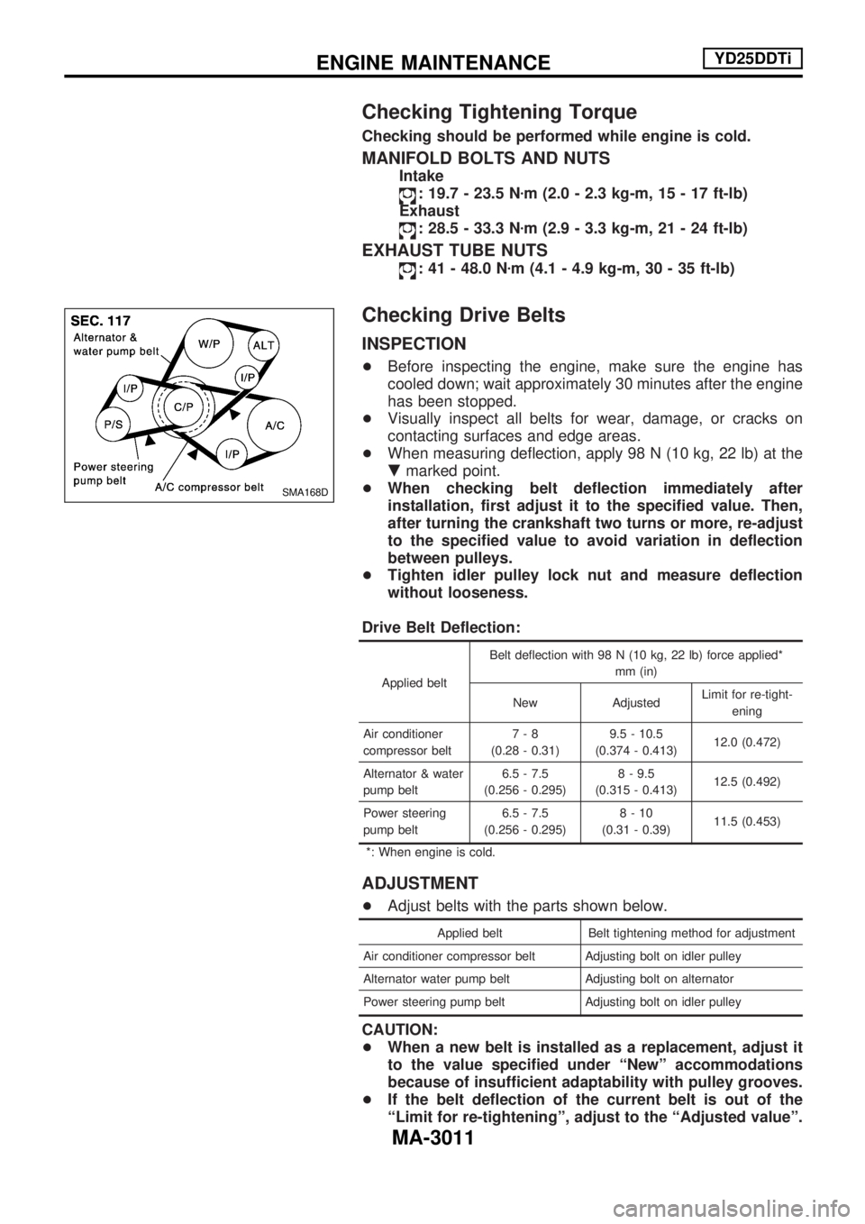
+When measuring deflection, apply 98 N (10 kg, 22 lb) at the
.marked point.
+When checking belt deflection immediately after
installation, first adjust it to the specified value. Then,
after turning the crankshaft two turns or more, re-adjust
to the specified value to avoid variation in deflection
between pulleys.
+Tighten idler pulley lock nut and measure deflection
without looseness.
Drive Belt Deflection:
Applied beltBelt deflection with 98 N (10 kg, 22 lb) force applied*
mm (in)
New AdjustedLimit for re-tight-
ening
Air conditioner
compressor belt7-8
(0.28 - 0.31)9.5 - 10.5
(0.374 - 0.413)12.0 (0.472)
Alternator & water
pump belt6.5 - 7.5
(0.256 - 0.295)8 - 9.5
(0.315 - 0.413)12.5 (0.492)
Power steering
pump belt6.5 - 7.5
(0.256 - 0.295)8-10
(0.31 - 0.39)11.5 (0.453)
*: When engine is cold.
ADJUSTMENT
+Adjust belts with the parts shown below.
Applied belt Belt tightening method for adjustment
Air conditioner compressor belt Adjusting bolt on idler pulley
Alternator water pump belt Adjusting bolt on alternator
Power steering pump belt Adjusting bolt on idler pulley
CAUTION:
+When a new belt is installed as a replacement, adjust it
to the value specified under ªNewº accommodations
because of insufficient adaptability with pulley grooves.
+If the belt deflection of the current belt is out of the
ªLimit for re-tighteningº, adjust to the ªAdjusted valueº.
SMA168D
ENGINE MAINTENANCEYD25DDTi
MA-3011
Page 1034 of 1306
+When checking belt deflection immediately after
installation, first adjust it to the specified value. Then,
after turning crankshaft two turns or more, re-adjust it to
the specified value to avoid variation in deflection
between pulleys.
+Make sure the belts are fully fitted into the pulley
grooves during installation.
+Handle with care to avoid smearing the belts with oil or
cooling water etc.
+Do not twist or bend the belts with strong force.
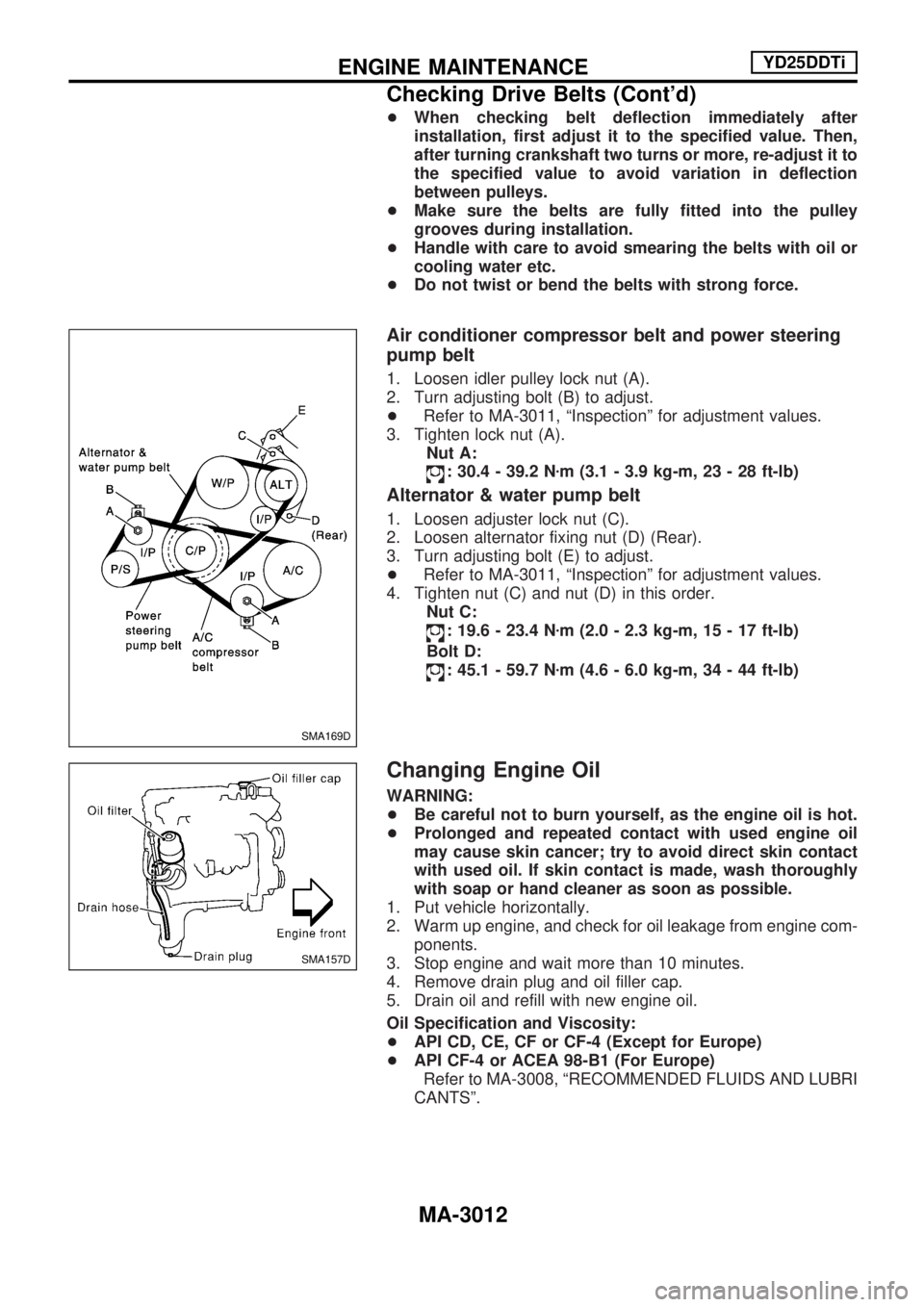
Air conditioner compressor belt and power steering
pump belt
1. Loosen idler pulley lock nut (A).
2. Turn adjusting bolt (B) to adjust.
+Refer to MA-3011, ªInspectionº for adjustment values.
3. Tighten lock nut (A).
Nut A:
: 30.4 - 39.2 Nzm (3.1 - 3.9 kg-m, 23 - 28 ft-lb)
Alternator & water pump belt
1. Loosen adjuster lock nut (C).
2. Loosen alternator fixing nut (D) (Rear).
3. Turn adjusting bolt (E) to adjust.
+Refer to MA-3011, ªInspectionº for adjustment values.
4. Tighten nut (C) and nut (D) in this order.
Nut C:
: 19.6 - 23.4 Nzm (2.0 - 2.3 kg-m, 15 - 17 ft-lb)
Bolt D:
: 45.1 - 59.7 Nzm (4.6 - 6.0 kg-m, 34 - 44 ft-lb)
Changing Engine Oil
WARNING:
+Be careful not to burn yourself, as the engine oil is hot.
+Prolonged and repeated contact with used engine oil
may cause skin cancer; try to avoid direct skin contact
with used oil. If skin contact is made, wash thoroughly
with soap or hand cleaner as soon as possible.
1. Put vehicle horizontally.
2. Warm up engine, and check for oil leakage from engine com-
ponents.
3. Stop engine and wait more than 10 minutes.
4. Remove drain plug and oil filler cap.
5. Drain oil and refill with new engine oil.
Oil Specification and Viscosity:
+API CD, CE, CF or CF-4 (Except for Europe)
+API CF-4 or ACEA 98-B1 (For Europe)
Refer to MA-3008, ªRECOMMENDED FLUIDS AND LUBRI
CANTSº.
SMA169D
SMA157D
ENGINE MAINTENANCEYD25DDTi
Checking Drive Belts (Cont'd)
MA-3012
Page 1042 of 1306
Engine Maintenance
INSPECTION AND ADJUSTMENT
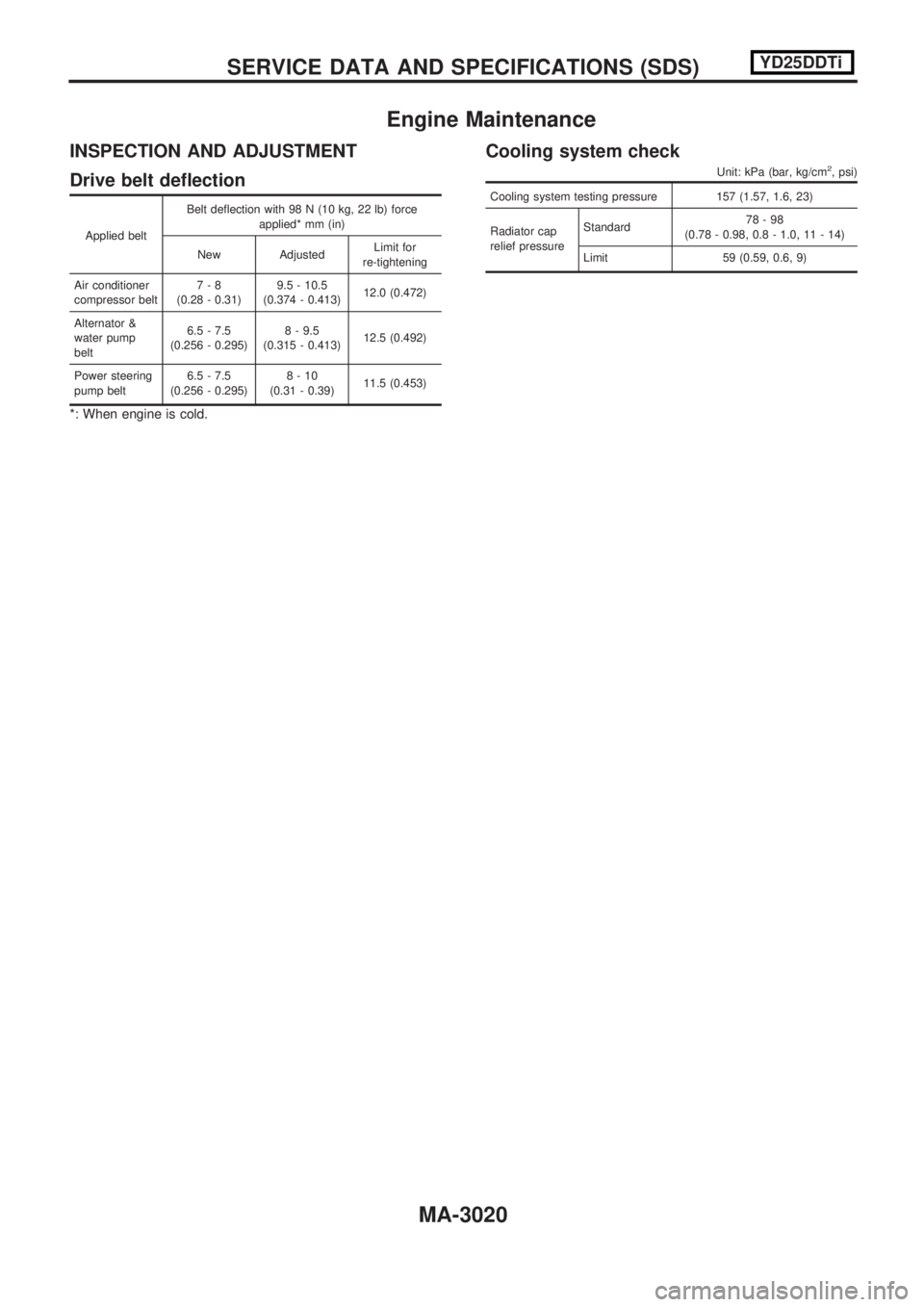
Drive belt deflection
Applied beltBelt deflection with 98 N (10 kg, 22 lb) force
applied* mm (in)
New Adjusted Limit for
re-tightening
Air conditioner
compressor belt 7-8
(0.28 - 0.31) 9.5 - 10.5
(0.374 - 0.413) 12.0 (0.472)
Alternator &
water pump
belt 6.5 - 7.5
(0.256 - 0.295) 8 - 9.5
(0.315 - 0.413) 12.5 (0.492)
Power steering
pump belt 6.5 - 7.5
(0.256 - 0.295) 8-10
(0.31 - 0.39) 11.5 (0.453)
*: When engine is cold.
Cooling system check
Unit: kPa (bar, kg/cm2, psi)
Cooling system testing pressure 157 (1.57, 1.6, 23)
Radiator cap
relief pressureStandard
78-98
(0.78 - 0.98, 0.8 - 1.0, 11 - 14)
Limit 59 (0.59, 0.6, 9)
SERVICEDATAANDSPECIFICATIONS(SDS) YD25DDTi
MA-3020
Page 1062 of 1306
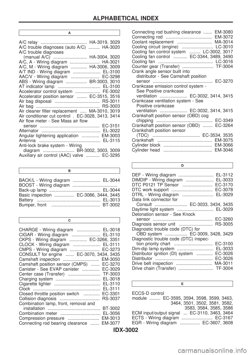
A
A/C relay ..................................... HA-3019, 3029
A/C trouble diagnoses (auto A/C) ......... HA-3020
A/C trouble diagnoses
(manual A/C) ........................... HA-3004, 3020
A/C, A - Wiring diagram ........................ HA-3021
A/C, M - Wiring diagram ............. HA-3006, 3009
A/T IND - Wiring diagram ...................... EL-3100
AAC/V - Wiring diagram ....................... EC-3298
ABS - Wiring diagram ................. BR-3003, 3010
AT indicator lamp .................................. EL-3100
Accelerator control system .................... FE-3002
Accelerator position sensor ........ EC-3515, 3516
Air bag disposal .................................... RS-3011
Air bag ................................................... RS-3003
Air cleaner filter replacement ..... MA-3010, 3019
Air conditioner cut control . EC-3028, 3413, 3414
Air flow meter - See Mass air flow
sensor ................................................ EC-3151
Alternator ............................................... EL-3022
Angular tightening application .............. EM-3003
Antenna ................................................. EL-3115
Anti-lock brake system - Wiring
diagram ......................... BR-3002, 3003, 3009
Auxiliary air control (AAC) valve ........... EC-3295
B
BACK/L - Wiring diagram ...................... EL-3044
BOOST - Wiring diagram ....................................
Back-up lamp ......................................... EL-3044
Basic inspection ................ EC-3086, 3444, 3445
Battery ................................................... EL-3013
Bumper, front ....................................... BT-3002
C
CHARGE - Wiring diagram ................... EL-3018
CIGAR - Wiring diagram ....................... EL-3110
CKPS - Wiring diagram .............. EC-3266, 3351
CLOCK - Wiring diagram ...................... EL-3111
CMPS - Wiring diagram ........................ EC-3273
CONSULT for engine ....... EC-3070, 3434, 3435
Camshaft inspection ............................. EM-3050
Camshaft position sensor (CMPS) ....... EC-3270
Canister - See EVAP canister .............. EC-3029
Center case (Transfer) .......................... TF-3003
Charging system .................................... EL-3018
Cigarette lighter ..................................... EL-3110
Clock ...................................................... EL-3111
Closed throttle position switch ............. EC-3301
Collision diagnosis ................................ RS-3037
Combination lamp, front, removal and
installation .......................................... BT-3002
Combination meter ................................ EL-3056
Compression pressure ......................... EM-3013
Connecting rod bearing clearance ....... EM-3077Connecting rod bushing clearance ....... EM-3080
Connecting rod ..................................... EM-3072
Coolant replacement ............................ MA-3014
Cooling circuit (engine) ......................... LC-3010
Cooling fan control system ......... LC-3002, 3017
Cooling fan control ........... EC-3344, 3489, 3490
Cooling fan ............................................ LC-3016
Counter gear (Transfer) ......................... TF-3004
Crank angle sensor built into
distributor - See Camshaft position
sensor ................................................ EC-3270
Crankcase emission control system -
See Positive crankcase
ventilation ...................... EC-3032, 3414, 3415
Crankcase ventilation system - See
Positive crankcase
ventilation ...................... EC-3032, 3414, 3415
Crankshaft position sensor (OBD) cog
chipping ............................................. EC-3349
Crankshaft position sensor (OBD) ........ EC-3264
Crankshaft position sensor
(TDC) ...................................... EC-3534, 3535
Crankshaft ............................................ EM-3075
Cylinder block ....................................... EM-3066
Cylinder head ....................................... EM-3046
D
DEF - Wiring diagram ............................ EL-3112
DIMDIP - Wiring diagram ...................... EL-3033
DTC P0121 TP Sensor ........................ EC-3170
DTC work support ................................. EC-3078
DTRL - Wiring diagram ......................... EL-3029
Data link connector for
Consult .......................... EC-3033, 3434, 3435
Daytime light system ............................. EL-3029
Detonation sensor - See Knock
sensor ................................................ EC-3260
Diagnosis sensor unit ........................... RS-3005
Diagnostic trouble code (DTC) for
OBD system .................. EC-3009, 3428, 3429
Diagnostic trouble code (DTC) inspec-
tion priority chart ............................... EC-3100
Dim-dip lamp system ............................. EL-3033
Distributor ignition (DI) system ............. EC-3026
Distributor .............................................. EC-3026
Drive belt inspection ............................. MA-3011
Drive chain (Transfer) ............................ TF-3004
E
ECCS-D control
module ......... EC-3595, 3594, 3598, 3599, 3463,
3464, 3501, 3502, 3581, 3582,
3583, 3584, 3585, 3586
ECM input/output signal ... EC-3110, 3463, 3464
ECTS - Wiring diagram ......................... EC-3167
EGR - Wiring diagram ................ EC-3607, 3608
ALPHABETICAL INDEX
IDX-3002