Page 893 of 1306
Removal
WARNING:
To avoid danger of being scalded, never drain engine oil
when engine is hot.
1. Raise vehicle and support it with safety stands.
2. Remove engine under cover.
3. Drain engine oil.
4. Remove lower oil pan bolts.
+Loosen bolts in the reverse order of that shown in the figure.
SEM850G
SEM851G
OIL PANYD25DDTi
EM-3016
Page 898 of 1306
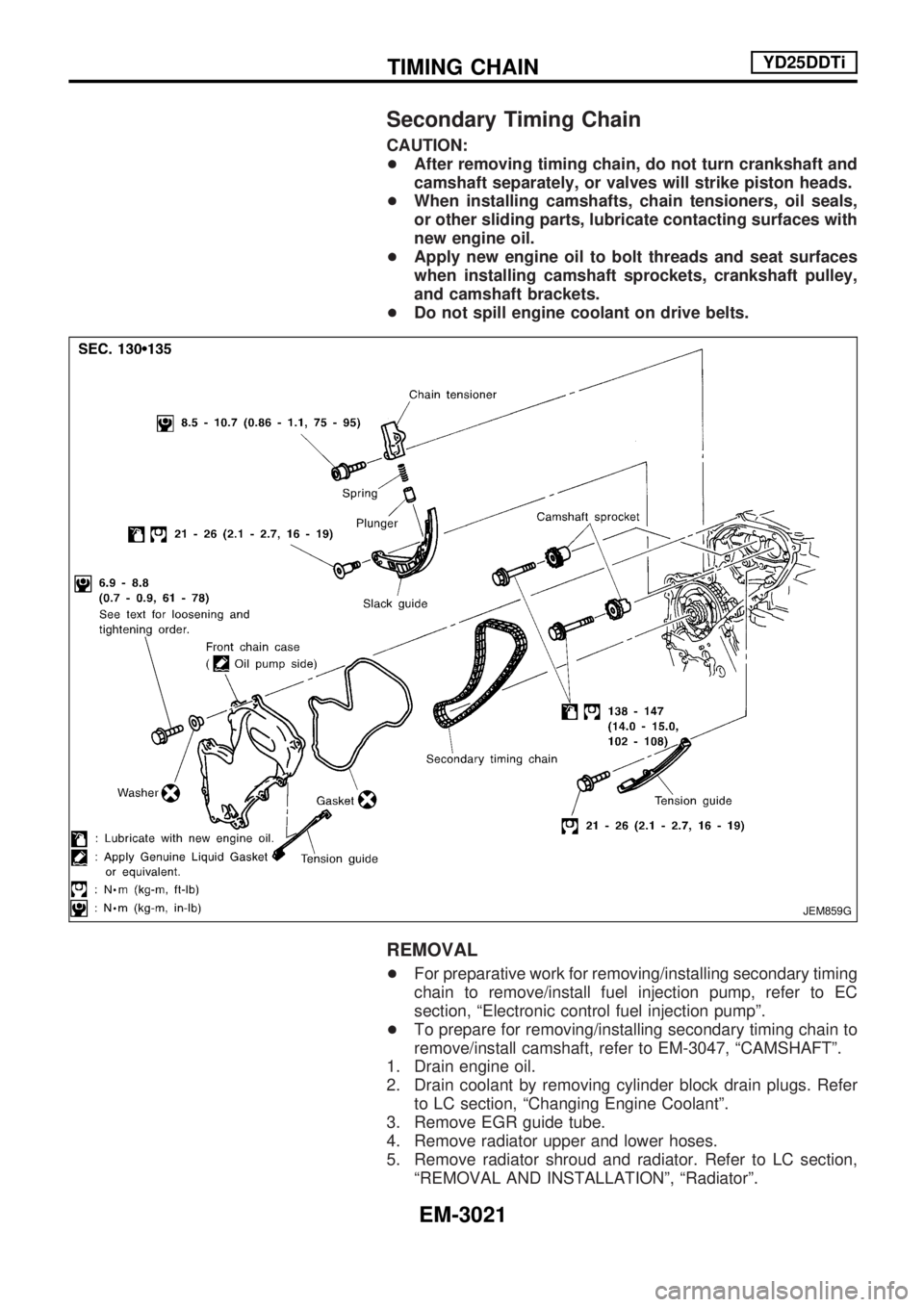
Secondary Timing Chain
CAUTION:
+After removing timing chain, do not turn crankshaft and
camshaft separately, or valves will strike piston heads.
+When installing camshafts, chain tensioners, oil seals,
or other sliding parts, lubricate contacting surfaces with
new engine oil.
+Apply new engine oil to bolt threads and seat surfaces
when installing camshaft sprockets, crankshaft pulley,
and camshaft brackets.
+Do not spill engine coolant on drive belts.
REMOVAL
+For preparative work for removing/installing secondary timing
chain to remove/install fuel injection pump, refer to EC
section, ªElectronic control fuel injection pumpº.
+To prepare for removing/installing secondary timing chain to
remove/install camshaft, refer to EM-3047, ªCAMSHAFTº.
1. Drain engine oil.
2. Drain coolant by removing cylinder block drain plugs. Refer
to LC section, ªChanging Engine Coolantº.
3. Remove EGR guide tube.
4. Remove radiator upper and lower hoses.
5. Remove radiator shroud and radiator. Refer to LC section,
ªREMOVAL AND INSTALLATIONº, ªRadiatorº.
JEM859G
TIMING CHAINYD25DDTi
EM-3021
Page 924 of 1306
CAUTION:
+When installing camshafts, chain tensioners, oil seals,
or other sliding parts, lubricate contacting surfaces with
new engine oil.
+Apply new engine oil to threads and seat surfaces when
installing cylinder head, camshaft sprocket, crankshaft
pulley, and camshaft bracket.
+Attach tags to valve lifters so as not to mix them up.
Removal
1. Drain engine coolant. Refer to LC section, ªChanging Engine
Coolantº.
2. Remove exhaust manifold, Turbocharger. Refer to EM-3039,
ªRemoval and Installationº.
3. Remove intake manifold. Refer to EM-3035, ªRemoval and
Installationº.
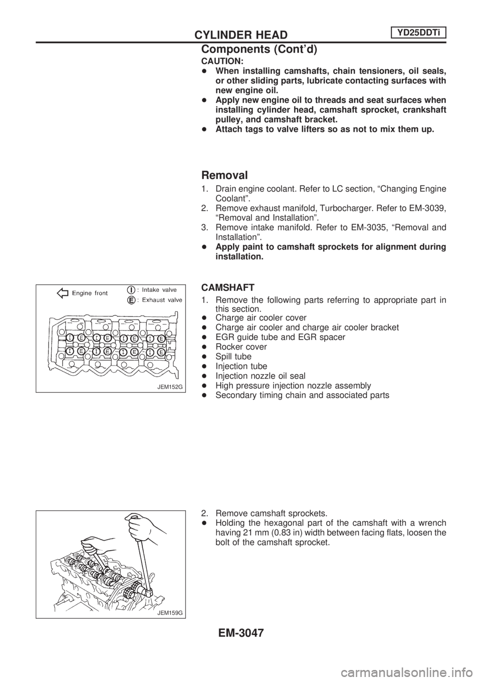
+Apply paint to camshaft sprockets for alignment during
installation.
CAMSHAFT
1. Remove the following parts referring to appropriate part in
this section.
+Charge air cooler cover
+Charge air cooler and charge air cooler bracket
+EGR guide tube and EGR spacer
+Rocker cover
+Spill tube
+Injection tube
+Injection nozzle oil seal
+High pressure injection nozzle assembly
+Secondary timing chain and associated parts
2. Remove camshaft sprockets.
+Holding the hexagonal part of the camshaft with a wrench
having 21 mm (0.83 in) width between facing flats, loosen the
bolt of the camshaft sprocket.
JEM152G
JEM159G
CYLINDER HEADYD25DDTi
Components (Cont'd)
EM-3047
Page 941 of 1306
Removal
Preparation
1. Drain coolant from radiator drain plugs.
2. Remove the following parts.
+Engine hood
+Charge air cooler
+Under protector
+Battery
+Radiator shroud
+Radiator
+Accessory belt
+Cooling fan
+Exhaust front tube
Engine room (Left)
3. Remove air duct and air cleaner case.
4. Disconnect harness connectors from alternator and air con-
ditioner compressor.
5. Remove alternator.
6. Remove installation bolts. Relocate air conditioner compres-
sor. Use a rope to temporarily anchor it to vehicle side.
7. Disconnect and relocate heating hose, install blank cap to
hose to prevent coolant from leaking.
8. Remove heat insulator.
Engine room (Right)
9. Remove fuel feed and return hoses.
CAUTION:
Install blank caps immediately to avoid fuel leakage.
10. Remove all harness connectors on the engine, and move
harnesses to the side of the vehicle.
Vehicle underfloor
11. Remove starter motor.
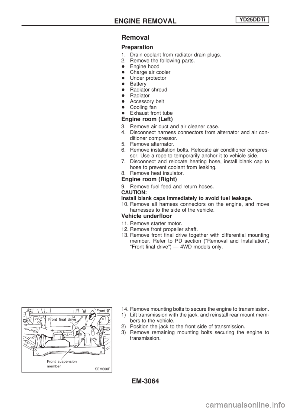
12. Remove front propeller shaft.
13. Remove front final drive together with differential mounting
member. Refer to PD section (ªRemoval and Installationº,
ªFront final driveº) Ð 4WD models only.
14. Remove mounting bolts to secure the engine to transmission.
1) Lift transmission with the jack, and reinstall rear mount mem-
bers to the vehicle.
2) Position the jack to the front side of transmission.
3) Remove remaining mounting bolts securing the engine to
transmission.
SEM600F
ENGINE REMOVALYD25DDTi
EM-3064
Page 1034 of 1306
+When checking belt deflection immediately after
installation, first adjust it to the specified value. Then,
after turning crankshaft two turns or more, re-adjust it to
the specified value to avoid variation in deflection
between pulleys.
+Make sure the belts are fully fitted into the pulley
grooves during installation.
+Handle with care to avoid smearing the belts with oil or
cooling water etc.
+Do not twist or bend the belts with strong force.
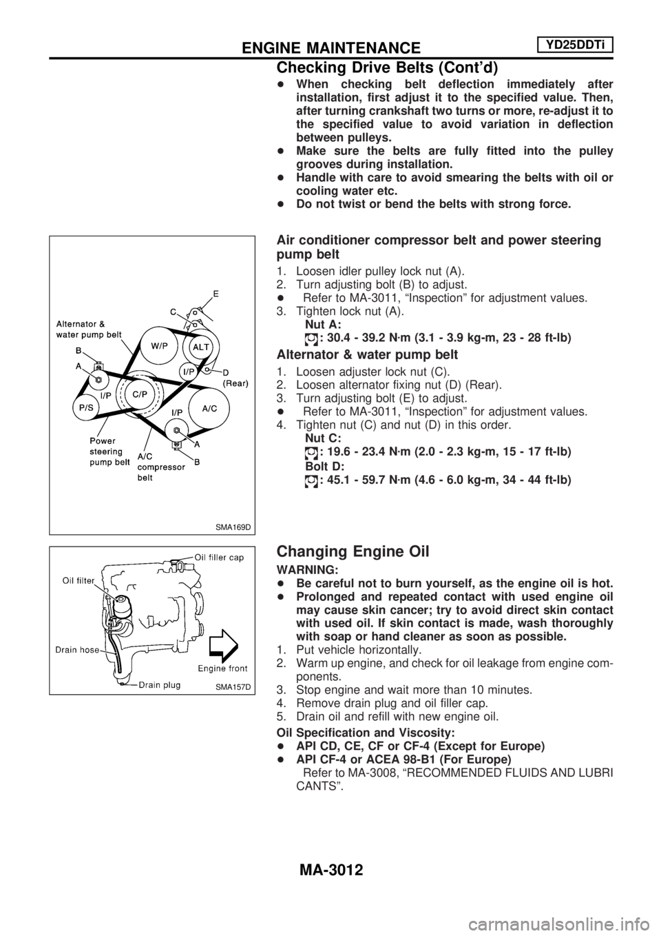
Air conditioner compressor belt and power steering
pump belt
1. Loosen idler pulley lock nut (A).
2. Turn adjusting bolt (B) to adjust.
+Refer to MA-3011, ªInspectionº for adjustment values.
3. Tighten lock nut (A).
Nut A:
: 30.4 - 39.2 Nzm (3.1 - 3.9 kg-m, 23 - 28 ft-lb)
Alternator & water pump belt
1. Loosen adjuster lock nut (C).
2. Loosen alternator fixing nut (D) (Rear).
3. Turn adjusting bolt (E) to adjust.
+Refer to MA-3011, ªInspectionº for adjustment values.
4. Tighten nut (C) and nut (D) in this order.
Nut C:
: 19.6 - 23.4 Nzm (2.0 - 2.3 kg-m, 15 - 17 ft-lb)
Bolt D:
: 45.1 - 59.7 Nzm (4.6 - 6.0 kg-m, 34 - 44 ft-lb)
Changing Engine Oil
WARNING:
+Be careful not to burn yourself, as the engine oil is hot.
+Prolonged and repeated contact with used engine oil
may cause skin cancer; try to avoid direct skin contact
with used oil. If skin contact is made, wash thoroughly
with soap or hand cleaner as soon as possible.
1. Put vehicle horizontally.
2. Warm up engine, and check for oil leakage from engine com-
ponents.
3. Stop engine and wait more than 10 minutes.
4. Remove drain plug and oil filler cap.
5. Drain oil and refill with new engine oil.
Oil Specification and Viscosity:
+API CD, CE, CF or CF-4 (Except for Europe)
+API CF-4 or ACEA 98-B1 (For Europe)
Refer to MA-3008, ªRECOMMENDED FLUIDS AND LUBRI
CANTSº.
SMA169D
SMA157D
ENGINE MAINTENANCEYD25DDTi
Checking Drive Belts (Cont'd)
MA-3012
Page 1040 of 1306
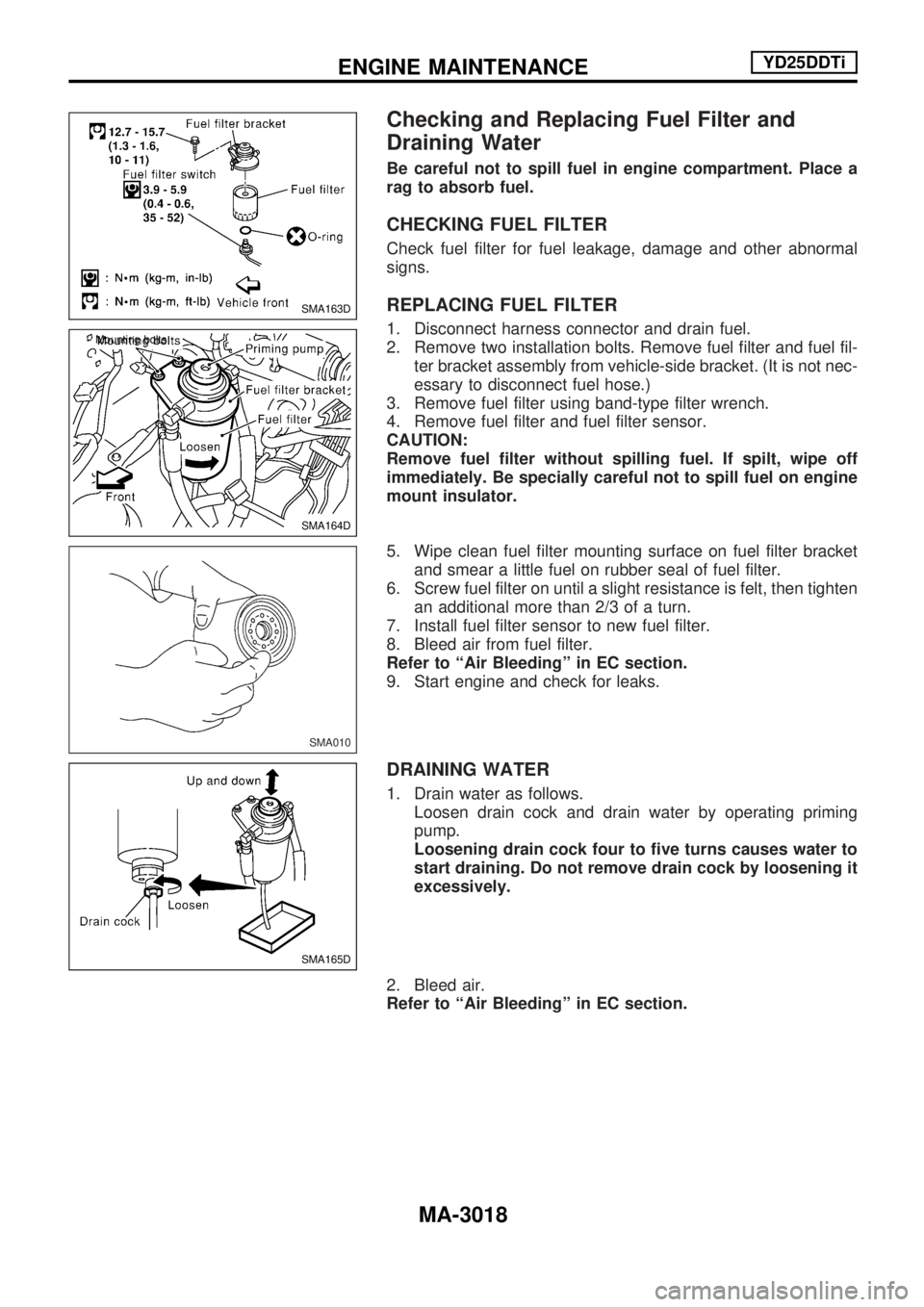
Checking and Replacing Fuel Filter and
Draining Water
Be careful not to spill fuel in engine compartment. Place a
rag to absorb fuel.
CHECKING FUEL FILTER
Check fuel filter for fuel leakage, damage and other abnormal
signs.
REPLACING FUEL FILTER
1. Disconnect harness connector and drain fuel.
2. Remove two installation bolts. Remove fuel filter and fuel fil-
ter bracket assembly from vehicle-side bracket. (It is not nec-
essary to disconnect fuel hose.)
3. Remove fuel filter using band-type filter wrench.
4. Remove fuel filter and fuel filter sensor.
CAUTION:
Remove fuel filter without spilling fuel. If spilt, wipe off
immediately. Be specially careful not to spill fuel on engine
mount insulator.
5. Wipe clean fuel filter mounting surface on fuel filter bracket
and smear a little fuel on rubber seal of fuel filter.
6. Screw fuel filter on until a slight resistance is felt, then tighten
an additional more than 2/3 of a turn.
7. Install fuel filter sensor to new fuel filter.
8. Bleed air from fuel filter.
Refer to ªAir Bleedingº in EC section.
9. Start engine and check for leaks.
DRAINING WATER
1. Drain water as follows.
Loosen drain cock and drain water by operating priming
pump.
Loosening drain cock four to five turns causes water to
start draining. Do not remove drain cock by loosening it
excessively.
2. Bleed air.
Refer to ªAir Bleedingº in EC section.
SMA163D
SMA164D Mounting bolts
SMA010
SMA165D
ENGINE MAINTENANCEYD25DDTi
MA-3018
Page 1048 of 1306
Oil Filter Bracket
REMOVAL
1. Remove oil filter. Refer to ªChanging Oil Filterº in MA section.
2. Loosen mounting bolts of oil filter bracket to drain the oil.
+Catch the oil with a pan or cloth.
3. Remove oil filter bracket.
INSTALLATION
1. Completely remove all foreign objects adhering to mounting
surfaces (cylinder block and bracket sides).
2. Install oil filter bracket with new gasket.
3. Install oil filter. Refer to ªChanging Oil Filterº in MA section.
OIL FILTER
The oil filter is an element type. Refer to ªChanging Oil Filterº in
MA section.
Oil Cooler
1. Oil cooler
2. Clamp
3. Water hose4. O-ring
5. Connecting bolt
6. Gasket7. Water hose connector
8. Oil filter bracket
9. Heater pipe
REMOVAL AND INSTALLATION
1. Draining the coolant
Refer to ªChanging Engine Coolantº in MA section.
SMA159D
SLC476B
ENGINE LUBRICATION SYSTEMYD25DDTi
LC-3006