2001 NISSAN PICK-UP change wheel
[x] Cancel search: change wheelPage 11 of 1306

BRAKE SYSTEM
SECTION
BR
MODIFICATION NOTICE:
lWiring Diagrams have been changed.
CONTENTS
TROUBLE DIAGNOSES..................................... 3002
Schematic/3 Wheel Sensors Models ............... 3002
Wiring Diagram - ABS -/3 Wheel Sensors LHD
Models.............................................................. 3003
Wiring Diagram - ABS -/3 Wheel Sensors
RHD Models..................................................... 3006Schematic/4 Wheel Sensors Models ............... 3009
Wiring Diagram - ABS -/4 Wheel Sensors LHD
Models.............................................................. 3010
Wiring Diagram - ABS -/4 Wheel Sensors
RHD Models..................................................... 3013
BR
Page 60 of 1306

SEF500V
Fast Idle Cam (FIC)
COMPONENT DESCRIPTIONNEEC0502The FIC is installed on the throttle body to maintain adequate
engine speed while the engine is cold. It is operated by a volumet-
ric change in wax located inside the thermo-element. The thermo-
element is operated by engine coolant temperature.
For inspection refer to ªTROUBLE DIAGNOSIS-BASIC
INSPECTIONº, ªBasic Inspectionº, EC-3086.
Idle Speed/Ignition Timing/Idle Mixture Ratio
Adjustment
NEEC0028PREPARATIONNEEC0028S05+Make sure that the following parts are in good order.
a)Battery
b)Ignition system
c)Engine oil and coolant levels
d)Fuses
e)ECM harness connector
f)Vacuum hoses
g)Air intake system
(Oil filler cap, oil level gauge, etc.)
h)Fuel pressure
i)Engine compression
j)Throttle valve
k)EVAP system
+On models equipped with air conditioner, checks should be carried out while the air conditioner is
ªOFFº.
+When measuring ªCOº percentage, insert probe more than 40 cm (15.7 in) into tail pipe.
+Turn off headlamps, heater blower.
+Keep front wheels pointed straight ahead.
BASIC SERVICE PROCEDUREKA24DE (EURO OBD)
Fast Idle Cam (FIC)
EC-3035
Page 131 of 1306
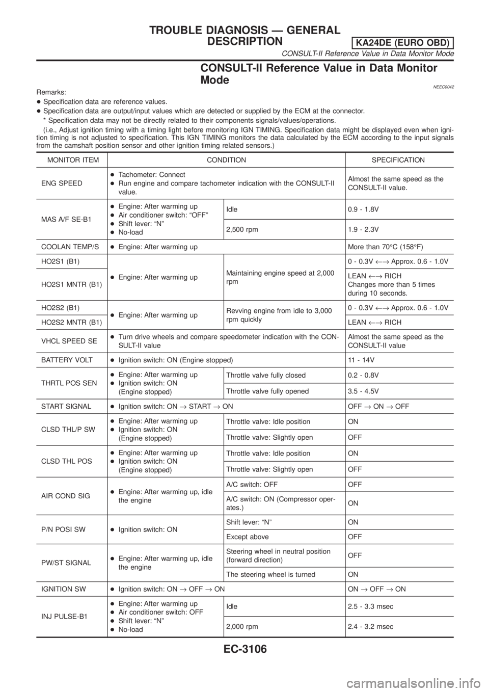
CONSULT-II Reference Value in Data Monitor
Mode
NEEC0042Remarks:
+Specification data are reference values.
+Specification data are output/input values which are detected or supplied by the ECM at the connector.
* Specification data may not be directly related to their components signals/values/operations.
(i.e., Adjust ignition timing with a timing light before monitoring IGN TIMING. Specification data might be displayed even when igni-
tion timing is not adjusted to specification. This IGN TIMING monitors the data calculated by the ECM according to the input signals
from the camshaft position sensor and other ignition timing related sensors.)
MONITOR ITEM CONDITION SPECIFICATION
ENG SPEED+Tachometer: Connect
+Run engine and compare tachometer indication with the CONSULT-II
value.Almost the same speed as the
CONSULT-II value.
MAS A/F SE-B1+Engine: After warming up
+Air conditioner switch: ªOFFº
+Shift lever: ªNº
+No-loadIdle 0.9 - 1.8V
2,500 rpm 1.9 - 2.3V
COOLAN TEMP/S+Engine: After warming up More than 70ÉC (158ÉF)
HO2S1 (B1)
+Engine: After warming upMaintaining engine speed at 2,000
rpm0 - 0.3V¨Approx. 0.6 - 1.0V
HO2S1 MNTR (B1)LEAN¨RICH
Changes more than 5 times
during 10 seconds.
HO2S2 (B1)
+Engine: After warming upRevving engine from idle to 3,000
rpm quickly0 - 0.3V¨Approx. 0.6 - 1.0V
HO2S2 MNTR (B1)LEAN¨RICH
VHCL SPEED SE+Turn drive wheels and compare speedometer indication with the CON-
SULT-II valueAlmost the same speed as the
CONSULT-II value
BATTERY VOLT+Ignition switch: ON (Engine stopped) 11 - 14V
THRTL POS SEN+Engine: After warming up
+Ignition switch: ON
(Engine stopped)Throttle valve fully closed 0.2 - 0.8V
Throttle valve fully opened 3.5 - 4.5V
START SIGNAL+Ignition switch: ON®START®ON OFF®ON®OFF
CLSD THL/P SW+Engine: After warming up
+Ignition switch: ON
(Engine stopped)Throttle valve: Idle position ON
Throttle valve: Slightly open OFF
CLSD THL POS+Engine: After warming up
+Ignition switch: ON
(Engine stopped)Throttle valve: Idle position ON
Throttle valve: Slightly open OFF
AIR COND SIG+Engine: After warming up, idle
the engineA/C switch: OFF OFF
A/C switch: ON (Compressor oper-
ates.)ON
P/N POSI SW+Ignition switch: ONShift lever: ªNº ON
Except above OFF
PW/ST SIGNAL+Engine: After warming up, idle
the engineSteering wheel in neutral position
(forward direction)OFF
The steering wheel is turned ON
IGNITION SW+Ignition switch: ON®OFF®ON ON®OFF®ON
INJ PULSE-B1+Engine: After warming up
+Air conditioner switch: OFF
+Shift lever: ªNº
+No-loadIdle 2.5 - 3.3 msec
2,000 rpm 2.4 - 3.2 msec
TROUBLE DIAGNOSIS Ð GENERAL
DESCRIPTION
KA24DE (EURO OBD)
CONSULT-II Reference Value in Data Monitor Mode
EC-3106
Page 276 of 1306
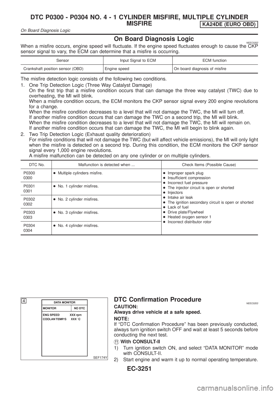
On Board Diagnosis LogicNEEC0202When a misfire occurs, engine speed will fluctuate. If the engine speed fluctuates enough to cause the CKP
sensor signal to vary, the ECM can determine that a misfire is occurring.
Sensor Input Signal to ECM ECM function
Crankshaft position sensor (OBD) Engine speed On board diagnosis of misfire
The misfire detection logic consists of the following two conditions.
1. One Trip Detection Logic (Three Way Catalyst Damage)
On the first trip that a misfire condition occurs that can damage the three way catalyst (TWC) due to
overheating, the MI will blink.
When a misfire condition occurs, the ECM monitors the CKP sensor signal every 200 engine revolutions
for a change.
When the misfire condition decreases to a level that will not damage the TWC, the MI will turn off.
If another misfire condition occurs that can damage the TWC on a second trip, the MI will blink.
When the misfire condition decreases to a level that will not damage the TWC, the MI will remain on.
If another misfire condition occurs that can damage the TWC, the MI will begin to blink again.
2. Two Trip Detection Logic (Exhaust quality deterioration)
For misfire conditions that will not damage the TWC (but will affect vehicle emissions), the MI will only light
when the misfire is detected on a second trip. During this condition, the ECM monitors the CKP sensor
signal every 1,000 engine revolutions.
A misfire malfunction can be detected on any one cylinder or on multiple cylinders.
DTC No. Malfunction is detected when ... Check Items (Possible Cause)
P0300
0300+Multiple cylinders misfire.+Improper spark plug
+Insufficient compression
+Incorrect fuel pressure
+The injector circuit is open or shorted
+Injectors
+Intake air leak
+The ignition secondary circuit is open or shorted
+Lack of fuel
+Drive plate/Flywheel
+Heated oxygen sensor 1
+Incorrect distributor rotor P0301
0301+No. 1 cylinder misfires.
P0302
0302+No. 2 cylinder misfires.
P0303
0303+No. 3 cylinder misfires.
P0304
0304+No. 4 cylinder misfires.
SEF174Y
DTC Confirmation ProcedureNEEC0203CAUTION:
Always drive vehicle at a safe speed.
NOTE:
If ªDTC Confirmation Procedureº has been previously conducted,
always turn ignition switch OFF and wait at least 5 seconds before
conducting the next test.
With CONSULT-II
1) Turn ignition switch ON, and select ªDATA MONITORº mode
with CONSULT-II.
2) Start engine and warm it up to normal operating temperature.
DTC P0300 - P0304 NO.4-1CYLINDER MISFIRE, MULTIPLE CYLINDER
MISFIRE
KA24DE (EURO OBD)
On Board Diagnosis Logic
EC-3251
Page 289 of 1306
SEF956N
SEF335V
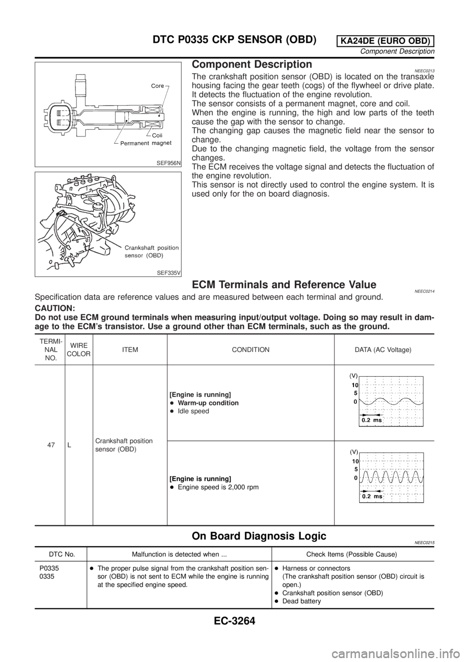
Component DescriptionNEEC0213The crankshaft position sensor (OBD) is located on the transaxle
housing facing the gear teeth (cogs) of the flywheel or drive plate.
It detects the fluctuation of the engine revolution.
The sensor consists of a permanent magnet, core and coil.
When the engine is running, the high and low parts of the teeth
cause the gap with the sensor to change.
The changing gap causes the magnetic field near the sensor to
change.
Due to the changing magnetic field, the voltage from the sensor
changes.
The ECM receives the voltage signal and detects the fluctuation of
the engine revolution.
This sensor is not directly used to control the engine system. It is
used only for the on board diagnosis.
ECM Terminals and Reference ValueNEEC0214Specification data are reference values and are measured between each terminal and ground.
CAUTION:
Do not use ECM ground terminals when measuring input/output voltage. Doing so may result in dam-
age to the ECM's transistor. Use a ground other than ECM terminals, such as the ground.
TERMI-
NAL
NO.WIRE
COLORITEM CONDITION DATA (AC Voltage)
47 LCrankshaft position
sensor (OBD)[Engine is running]
+Warm-up condition
+Idle speed
[Engine is running]
+Engine speed is 2,000 rpm
On Board Diagnosis LogicNEEC0215
DTC No. Malfunction is detected when ... Check Items (Possible Cause)
P0335
0335+The proper pulse signal from the crankshaft position sen-
sor (OBD) is not sent to ECM while the engine is running
at the specified engine speed.+Harness or connectors
(The crankshaft position sensor (OBD) circuit is
open.)
+Crankshaft position sensor (OBD)
+Dead battery
DTC P0335 CKP SENSOR (OBD)KA24DE (EURO OBD)
Component Description
EC-3264
Page 374 of 1306
SEF956N
SEF335V
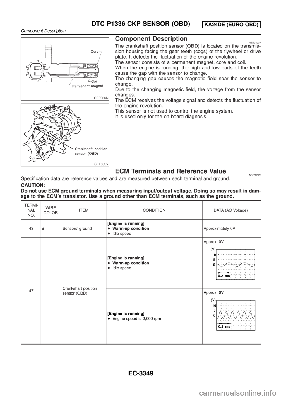
Component DescriptionNEEC0327The crankshaft position sensor (OBD) is located on the transmis-
sion housing facing the gear teeth (cogs) of the flywheel or drive
plate. It detects the fluctuation of the engine revolution.
The sensor consists of a permanent magnet, core and coil.
When the engine is running, the high and low parts of the teeth
cause the gap with the sensor to change.
The changing gap causes the magnetic field near the sensor to
change.
Due to the changing magnetic field, the voltage from the sensor
changes.
The ECM receives the voltage signal and detects the fluctuation of
the engine revolution.
This sensor is not used to control the engine system.
It is used only for the on board diagnosis.
ECM Terminals and Reference ValueNEEC0328Specification data are reference values and are measured between each terminal and ground.
CAUTION:
Do not use ECM ground terminals when measuring input/output voltage. Doing so may result in dam-
age to the ECM's transistor. Use a ground other than ECM terminals, such as the ground.
TERMI-
NAL
NO.WIRE
COLORITEM CONDITION DATA (AC Voltage)
43 B Sensors' ground[Engine is running]
+Warm-up condition
+Idle speedApproximately 0V
47 LCrankshaft position
sensor (OBD)[Engine is running]
+Warm-up condition
+Idle speedApprox. 0V
[Engine is running]
+Engine speed is 2,000 rpmApprox. 0V
DTC P1336 CKP SENSOR (OBD)KA24DE (EURO OBD)
Component Description
EC-3349
Page 533 of 1306
Description
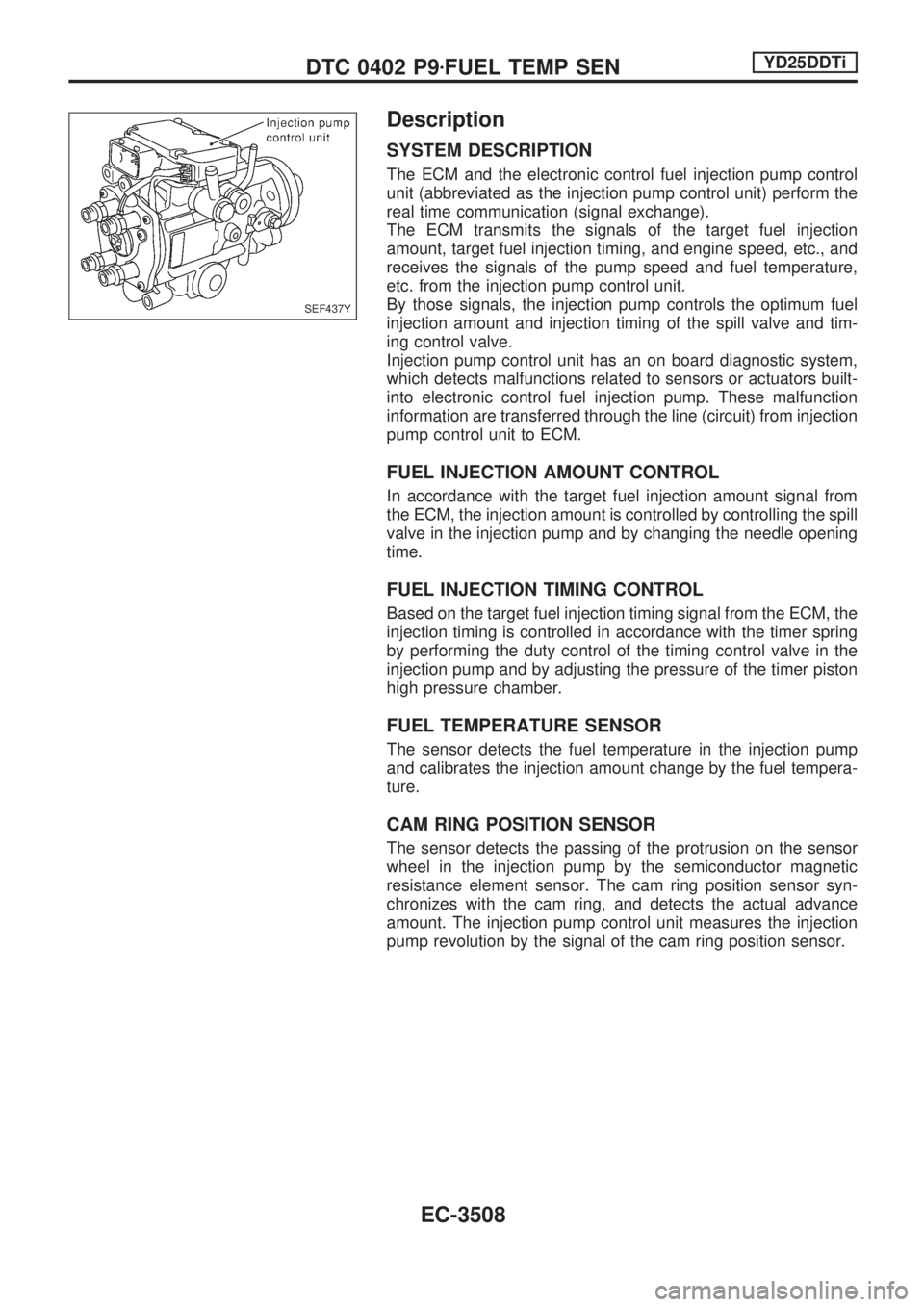
SYSTEM DESCRIPTION
The ECM and the electronic control fuel injection pump control
unit (abbreviated as the injection pump control unit) perform the
real time communication (signal exchange).
The ECM transmits the signals of the target fuel injection
amount, target fuel injection timing, and engine speed, etc., and
receives the signals of the pump speed and fuel temperature,
etc. from the injection pump control unit.
By those signals, the injection pump controls the optimum fuel
injection amount and injection timing of the spill valve and tim-
ing control valve.
Injection pump control unit has an on board diagnostic system,
which detects malfunctions related to sensors or actuators built-
into electronic control fuel injection pump. These malfunction
information are transferred through the line (circuit) from injection
pump control unit to ECM.
FUEL INJECTION AMOUNT CONTROL
In accordance with the target fuel injection amount signal from
the ECM, the injection amount is controlled by controlling the spill
valve in the injection pump and by changing the needle opening
time.
FUEL INJECTION TIMING CONTROL
Based on the target fuel injection timing signal from the ECM, the
injection timing is controlled in accordance with the timer spring
by performing the duty control of the timing control valve in the
injection pump and by adjusting the pressure of the timer piston
high pressure chamber.
FUEL TEMPERATURE SENSOR
The sensor detects the fuel temperature in the injection pump
and calibrates the injection amount change by the fuel tempera-
ture.
CAM RING POSITION SENSOR
The sensor detects the passing of the protrusion on the sensor
wheel in the injection pump by the semiconductor magnetic
resistance element sensor. The cam ring position sensor syn-
chronizes with the cam ring, and detects the actual advance
amount. The injection pump control unit measures the injection
pump revolution by the signal of the cam ring position sensor.
SEF437Y
DTC 0402 P9zFUEL TEMP SENYD25DDTi
EC-3508
Page 567 of 1306
Description
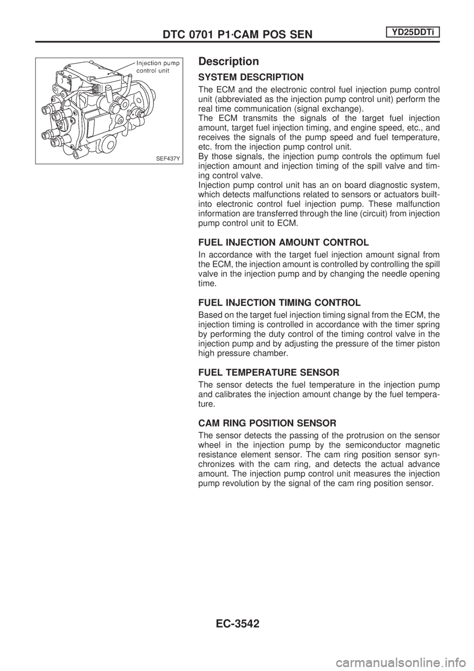
SYSTEM DESCRIPTION
The ECM and the electronic control fuel injection pump control
unit (abbreviated as the injection pump control unit) perform the
real time communication (signal exchange).
The ECM transmits the signals of the target fuel injection
amount, target fuel injection timing, and engine speed, etc., and
receives the signals of the pump speed and fuel temperature,
etc. from the injection pump control unit.
By those signals, the injection pump controls the optimum fuel
injection amount and injection timing of the spill valve and tim-
ing control valve.
Injection pump control unit has an on board diagnostic system,
which detects malfunctions related to sensors or actuators built-
into electronic control fuel injection pump. These malfunction
information are transferred through the line (circuit) from injection
pump control unit to ECM.
FUEL INJECTION AMOUNT CONTROL
In accordance with the target fuel injection amount signal from
the ECM, the injection amount is controlled by controlling the spill
valve in the injection pump and by changing the needle opening
time.
FUEL INJECTION TIMING CONTROL
Based on the target fuel injection timing signal from the ECM, the
injection timing is controlled in accordance with the timer spring
by performing the duty control of the timing control valve in the
injection pump and by adjusting the pressure of the timer piston
high pressure chamber.
FUEL TEMPERATURE SENSOR
The sensor detects the fuel temperature in the injection pump
and calibrates the injection amount change by the fuel tempera-
ture.
CAM RING POSITION SENSOR
The sensor detects the passing of the protrusion on the sensor
wheel in the injection pump by the semiconductor magnetic
resistance element sensor. The cam ring position sensor syn-
chronizes with the cam ring, and detects the actual advance
amount. The injection pump control unit measures the injection
pump revolution by the signal of the cam ring position sensor.
SEF437Y
DTC 0701 P1zCAM POS SENYD25DDTi
EC-3542