Page 280 of 1306
7 CHECK SPARK PLUGS
Remove the spark plugs and check for fouling, etc.
SEF156I
OK or NG
OK©GO TO 8.
NG©Repair or replace spark plug(s) with standard type one(s). For spark plug type, refer to
ªENGINE MAINTENANCEº, MA section.
8 CHECK COMPRESSION PRESSURE
Refer to EM section.
+Check compression pressure.
Standard:
1,226 kPa (12.3 bar, 12.5 kg/cm
2, 178 psi)/300 rpm
Minimum:
1,030 kPa (10.3 bar, 10.5 kg/cm
2, 149 psi)/300 rpm
Difference between each cylinder:
98 kPa (0.98 bar, 1.0 kg/cm
2, 14 psi)/300 rpm
OK or NG
OK©GO TO 9.
NG©Check pistons, piston rings, valves, valve seats and cylinder head gaskets.
9 CHECK FUEL PRESSURE
1. Install any parts removed.
2. Release fuel pressure to zero. Refer to EC-3033.
3. Install fuel pressure gauge and check fuel pressure.
AEC064B
At idle: Approx. 235 kPa (2.35 bar, 2.4 kg/cm2, 34 psi)
OK or NG
OK©GO TO 11.
NG©GO TO 10.
DTC P0300 - P0304 NO.4-1CYLINDER MISFIRE, MULTIPLE CYLINDER
MISFIRE
KA24DE (EURO OBD)
Diagnostic Procedure
EC-3255
Page 890 of 1306

1. Warm up engine.
2. Turn ignition switch OFF.
3. Using CONSULT-II, make sure no error codes are indicated
for self-diagnosis items. Refer to ªTrouble Diagnosis Ð
INDEXº in EC section.
+Do not disconnect CONSULT-II until the end of this opera-
tion; it will be used to check engine rpm and for error detec-
tion at the end of this operation.
4. Disconnect the negative battery terminal.
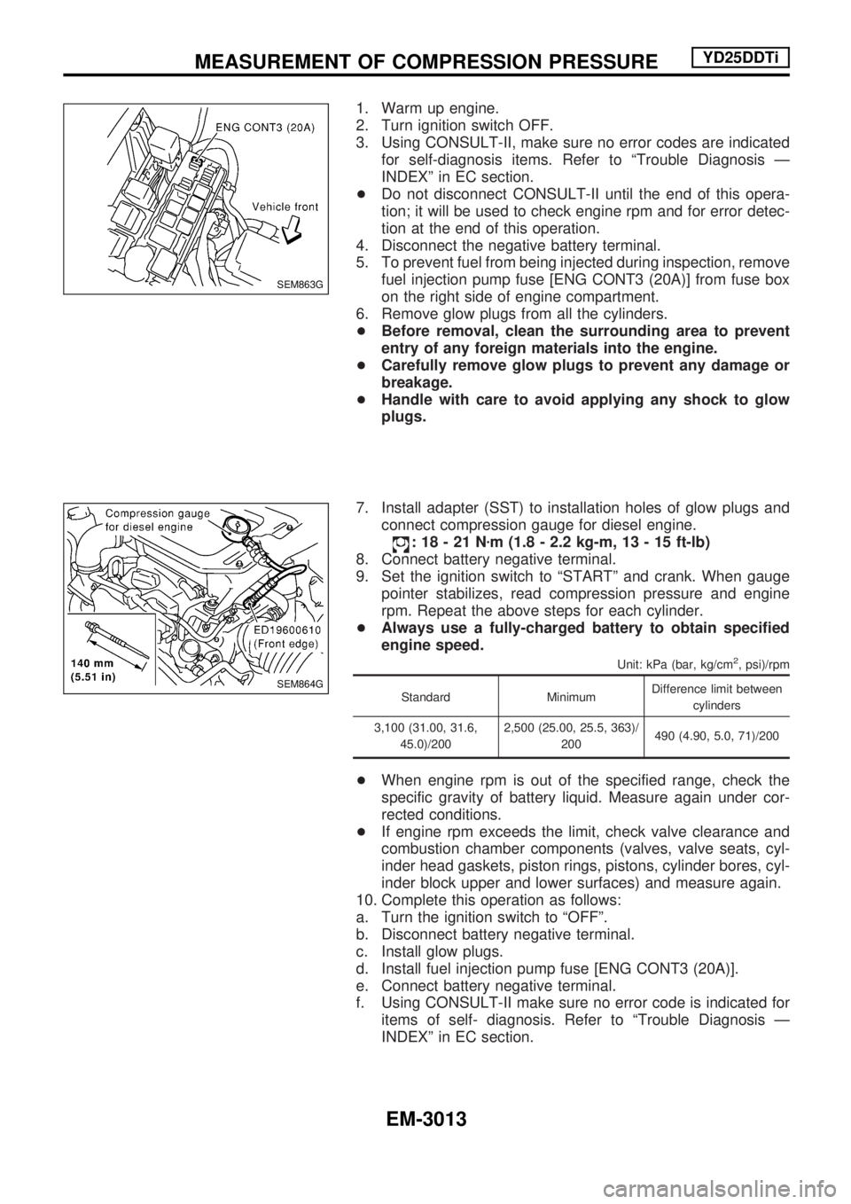
5. To prevent fuel from being injected during inspection, remove
fuel injection pump fuse [ENG CONT3 (20A)] from fuse box
on the right side of engine compartment.
6. Remove glow plugs from all the cylinders.
+Before removal, clean the surrounding area to prevent
entry of any foreign materials into the engine.
+Carefully remove glow plugs to prevent any damage or
breakage.
+Handle with care to avoid applying any shock to glow
plugs.
7. Install adapter (SST) to installation holes of glow plugs and
connect compression gauge for diesel engine.
:18-21Nzm (1.8 - 2.2 kg-m, 13 - 15 ft-lb)
8. Connect battery negative terminal.
9. Set the ignition switch to ªSTARTº and crank. When gauge
pointer stabilizes, read compression pressure and engine
rpm. Repeat the above steps for each cylinder.
+Always use a fully-charged battery to obtain specified
engine speed.
Unit: kPa (bar, kg/cm2, psi)/rpm
Standard MinimumDifference limit between
cylinders
3,100 (31.00, 31.6,
45.0)/2002,500 (25.00, 25.5, 363)/
200490 (4.90, 5.0, 71)/200
+When engine rpm is out of the specified range, check the
specific gravity of battery liquid. Measure again under cor-
rected conditions.
+If engine rpm exceeds the limit, check valve clearance and
combustion chamber components (valves, valve seats, cyl-
inder head gaskets, piston rings, pistons, cylinder bores, cyl-
inder block upper and lower surfaces) and measure again.
10. Complete this operation as follows:
a. Turn the ignition switch to ªOFFº.
b. Disconnect battery negative terminal.
c. Install glow plugs.
d. Install fuel injection pump fuse [ENG CONT3 (20A)].
e. Connect battery negative terminal.
f. Using CONSULT-II make sure no error code is indicated for
items of self- diagnosis. Refer to ªTrouble Diagnosis Ð
INDEXº in EC section.
SEM863G
SEM864G
MEASUREMENT OF COMPRESSION PRESSUREYD25DDTi
EM-3013
Page 926 of 1306

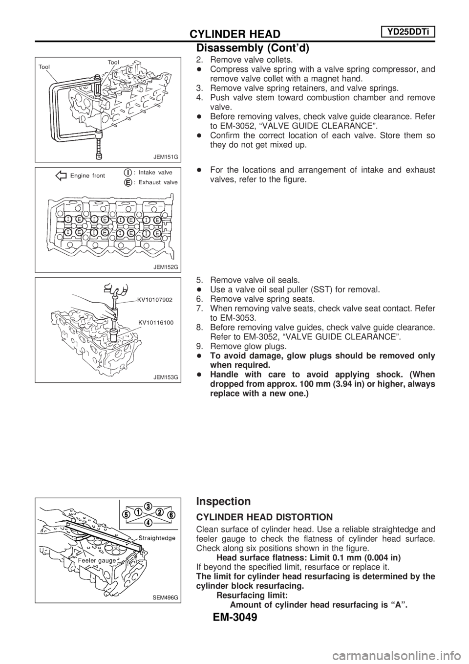
2. Remove valve collets.
+Compress valve spring with a valve spring compressor, and
remove valve collet with a magnet hand.
3. Remove valve spring retainers, and valve springs.
4. Push valve stem toward combustion chamber and remove valve.
+ Before removing valves, check valve guide clearance. Refer
to EM-3052, ªVALVE GUIDE CLEARANCEº.
+ Confirm the correct location of each valve. Store them so
they do not get mixed up.
+ For the locations and arrangement of intake and exhaust
valves, refer to the figure.
5. Remove valve oil seals.
+ Use a valve oil seal puller (SST) for removal.
6. Remove valve spring seats.
7. When removing valve seats, check valve seat contact. Refer to EM-3053.
8. Before removing valve guides, check valve guide clearance. Refer to EM-3052, ªVALVE GUIDE CLEARANCEº.
9. Remove glow plugs.
+ To avoid damage, glow plugs should be removed only
when required.
+ Handle with care to avoid applying shock. (When
dropped from approx. 100 mm (3.94 in) or higher, always
replace with a new one.)
Inspection
CYLINDER HEAD DISTORTION
Clean surface of cylinder head. Use a reliable straightedge and
feeler gauge to check the flatness of cylinder head surface.
Check along six positions shown in the figure.
Headsurfaceflatness:Limit0.1 mm(0.004 in)
If beyond the specified limit, resurface or replace it.
The limit for cylinder head resurfacing is determined by the
cylinder block resurfacing. Resurfacing limit:Amount of cylinder head resurfacing is ªAº.
JEM151G
JEM152G
JEM153G
SEM496G
CYLINDER HEADYD25DDTi
Disassembly (Cont'd)
EM-3049