Page 280 of 1306
7 CHECK SPARK PLUGS
Remove the spark plugs and check for fouling, etc.
SEF156I
OK or NG
OK©GO TO 8.
NG©Repair or replace spark plug(s) with standard type one(s). For spark plug type, refer to
ªENGINE MAINTENANCEº, MA section.
8 CHECK COMPRESSION PRESSURE
Refer to EM section.
+Check compression pressure.
Standard:
1,226 kPa (12.3 bar, 12.5 kg/cm
2, 178 psi)/300 rpm
Minimum:
1,030 kPa (10.3 bar, 10.5 kg/cm
2, 149 psi)/300 rpm
Difference between each cylinder:
98 kPa (0.98 bar, 1.0 kg/cm
2, 14 psi)/300 rpm
OK or NG
OK©GO TO 9.
NG©Check pistons, piston rings, valves, valve seats and cylinder head gaskets.
9 CHECK FUEL PRESSURE
1. Install any parts removed.
2. Release fuel pressure to zero. Refer to EC-3033.
3. Install fuel pressure gauge and check fuel pressure.
AEC064B
At idle: Approx. 235 kPa (2.35 bar, 2.4 kg/cm2, 34 psi)
OK or NG
OK©GO TO 11.
NG©GO TO 10.
DTC P0300 - P0304 NO.4-1CYLINDER MISFIRE, MULTIPLE CYLINDER
MISFIRE
KA24DE (EURO OBD)
Diagnostic Procedure
EC-3255
Page 890 of 1306

1. Warm up engine.
2. Turn ignition switch OFF.
3. Using CONSULT-II, make sure no error codes are indicated
for self-diagnosis items. Refer to ªTrouble Diagnosis Ð
INDEXº in EC section.
+Do not disconnect CONSULT-II until the end of this opera-
tion; it will be used to check engine rpm and for error detec-
tion at the end of this operation.
4. Disconnect the negative battery terminal.
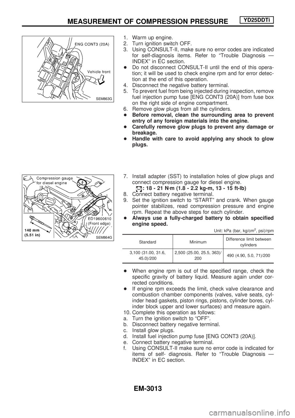
5. To prevent fuel from being injected during inspection, remove
fuel injection pump fuse [ENG CONT3 (20A)] from fuse box
on the right side of engine compartment.
6. Remove glow plugs from all the cylinders.
+Before removal, clean the surrounding area to prevent
entry of any foreign materials into the engine.
+Carefully remove glow plugs to prevent any damage or
breakage.
+Handle with care to avoid applying any shock to glow
plugs.
7. Install adapter (SST) to installation holes of glow plugs and
connect compression gauge for diesel engine.
:18-21Nzm (1.8 - 2.2 kg-m, 13 - 15 ft-lb)
8. Connect battery negative terminal.
9. Set the ignition switch to ªSTARTº and crank. When gauge
pointer stabilizes, read compression pressure and engine
rpm. Repeat the above steps for each cylinder.
+Always use a fully-charged battery to obtain specified
engine speed.
Unit: kPa (bar, kg/cm2, psi)/rpm
Standard MinimumDifference limit between
cylinders
3,100 (31.00, 31.6,
45.0)/2002,500 (25.00, 25.5, 363)/
200490 (4.90, 5.0, 71)/200
+When engine rpm is out of the specified range, check the
specific gravity of battery liquid. Measure again under cor-
rected conditions.
+If engine rpm exceeds the limit, check valve clearance and
combustion chamber components (valves, valve seats, cyl-
inder head gaskets, piston rings, pistons, cylinder bores, cyl-
inder block upper and lower surfaces) and measure again.
10. Complete this operation as follows:
a. Turn the ignition switch to ªOFFº.
b. Disconnect battery negative terminal.
c. Install glow plugs.
d. Install fuel injection pump fuse [ENG CONT3 (20A)].
e. Connect battery negative terminal.
f. Using CONSULT-II make sure no error code is indicated for
items of self- diagnosis. Refer to ªTrouble Diagnosis Ð
INDEXº in EC section.
SEM863G
SEM864G
MEASUREMENT OF COMPRESSION PRESSUREYD25DDTi
EM-3013
Page 926 of 1306

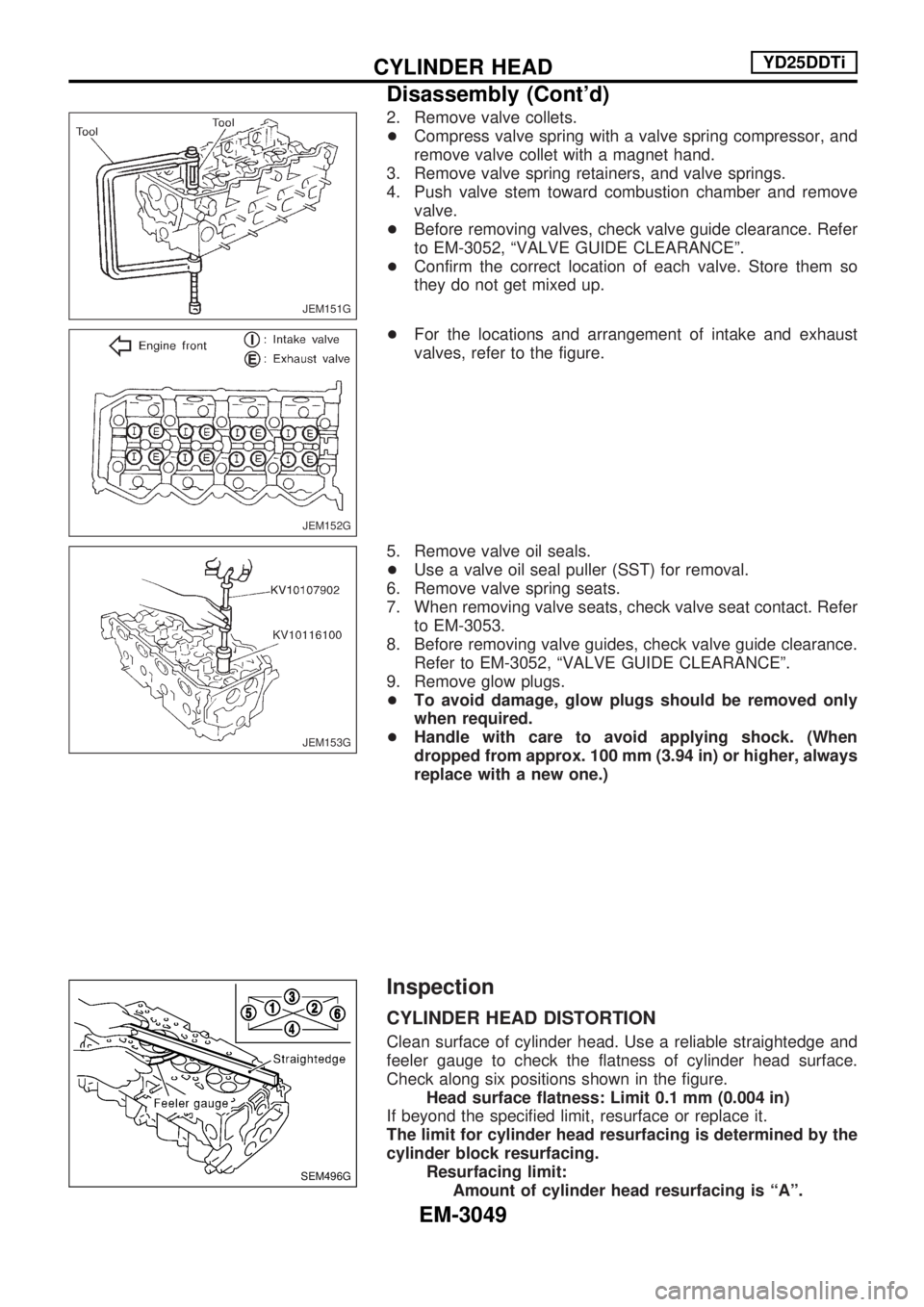
2. Remove valve collets.
+Compress valve spring with a valve spring compressor, and
remove valve collet with a magnet hand.
3. Remove valve spring retainers, and valve springs.
4. Push valve stem toward combustion chamber and remove valve.
+ Before removing valves, check valve guide clearance. Refer
to EM-3052, ªVALVE GUIDE CLEARANCEº.
+ Confirm the correct location of each valve. Store them so
they do not get mixed up.
+ For the locations and arrangement of intake and exhaust
valves, refer to the figure.
5. Remove valve oil seals.
+ Use a valve oil seal puller (SST) for removal.
6. Remove valve spring seats.
7. When removing valve seats, check valve seat contact. Refer to EM-3053.
8. Before removing valve guides, check valve guide clearance. Refer to EM-3052, ªVALVE GUIDE CLEARANCEº.
9. Remove glow plugs.
+ To avoid damage, glow plugs should be removed only
when required.
+ Handle with care to avoid applying shock. (When
dropped from approx. 100 mm (3.94 in) or higher, always
replace with a new one.)
Inspection
CYLINDER HEAD DISTORTION
Clean surface of cylinder head. Use a reliable straightedge and
feeler gauge to check the flatness of cylinder head surface.
Check along six positions shown in the figure.
Headsurfaceflatness:Limit0.1 mm(0.004 in)
If beyond the specified limit, resurface or replace it.
The limit for cylinder head resurfacing is determined by the
cylinder block resurfacing. Resurfacing limit:Amount of cylinder head resurfacing is ªAº.
JEM151G
JEM152G
JEM153G
SEM496G
CYLINDER HEADYD25DDTi
Disassembly (Cont'd)
EM-3049
Page 930 of 1306

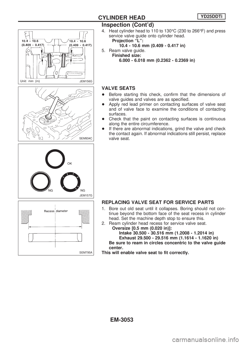
4. Heat cylinder head to 110 to 130ÉC (230 to 266ÉF) and press
service valve guide onto cylinder head.
Projection ªLº:
10.4 - 10.6 mm (0.409 - 0.417 in)
5. Ream valve guide.
Finished size:
6.000 - 6.018 mm (0.2362 - 0.2369 in)
VALVE SEATS
+Before starting this check, confirm that the dimensions of
valve guides and valves are as specified.
+Apply red lead primer on contacting surfaces of valve seat
and of valve face to examine the conditions of contacting
surfaces.
+Check that the paint on contacting surfaces is continuous
along the entire circumference.
+If there are abnormal indications, grind the valve and check
the contact again. If abnormal indications still persist, replace
valve seat.
REPLACING VALVE SEAT FOR SERVICE PARTS
1. Bore out old seat until it collapses. Boring should not con-
tinue beyond the bottom face of the seat recess in cylinder
head. Set the machine depth stop to ensure this.
2. Ream cylinder head recess for service valve seat.
Oversize [0.5 mm (0.020 in)]:
Intake 30.500 - 30.516 mm (1.2008 - 1.2014 in)
Exhaust 29.500 - 29.516 mm (1.1614 - 1.1620 in)
Be sure to ream in circles concentric to the valve guide
center.
This will enable valve seat to fit correctly.
JEM156G
SEM934C
JEM157G
SEM795A
CYLINDER HEADYD25DDTi
Inspection (Cont'd)
EM-3053
Page 931 of 1306

3. Heat cylinder head to 110 to 120ÉC (230 to 248ÉF) by soak-
ing in heated oil.
4. Sufficiently cool valve seat with dry ice. Force fit valve seat
into cylinder head.
WARNING:
Do not touch cold valve seat with your bare hands.
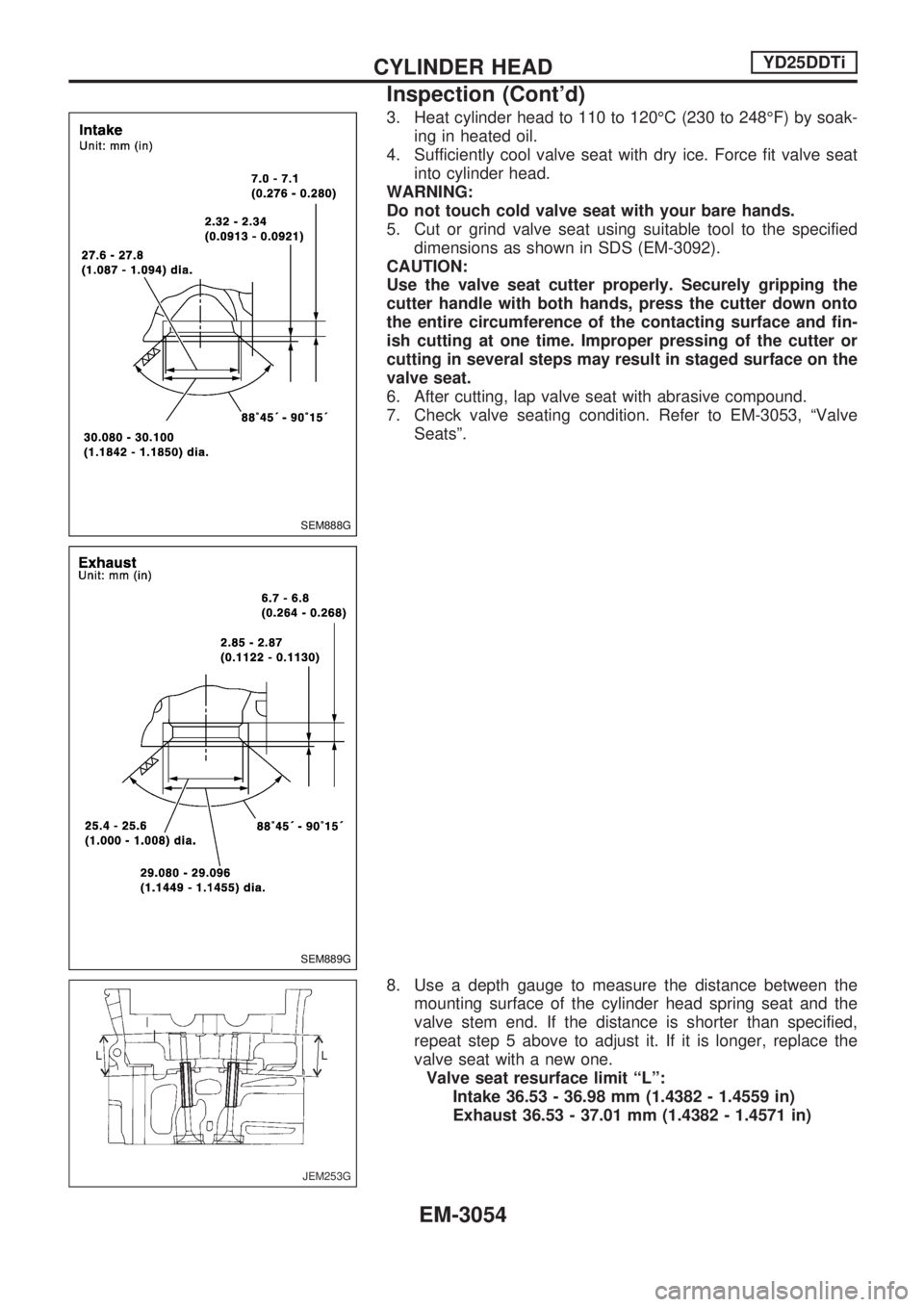
5. Cut or grind valve seat using suitable tool to the specified
dimensions as shown in SDS (EM-3092).
CAUTION:
Use the valve seat cutter properly. Securely gripping the
cutter handle with both hands, press the cutter down onto
the entire circumference of the contacting surface and fin-
ish cutting at one time. Improper pressing of the cutter or
cutting in several steps may result in staged surface on the
valve seat.
6. After cutting, lap valve seat with abrasive compound.
7. Check valve seating condition. Refer to EM-3053, ªValve
Seatsº.
8. Use a depth gauge to measure the distance between the
mounting surface of the cylinder head spring seat and the
valve stem end. If the distance is shorter than specified,
repeat step 5 above to adjust it. If it is longer, replace the
valve seat with a new one.
Valve seat resurface limit ªLº:
Intake 36.53 - 36.98 mm (1.4382 - 1.4559 in)
Exhaust 36.53 - 37.01 mm (1.4382 - 1.4571 in)
SEM888G
SEM889G
JEM253G
CYLINDER HEADYD25DDTi
Inspection (Cont'd)
EM-3054