2001 NISSAN PICK-UP checking oil
[x] Cancel search: checking oilPage 369 of 1306
On Board Diagnosis LogicNEEC1534If the cooling fan or another component in the cooling system malfunctions, engine coolant temperature will
rise.
When the engine coolant temperature reaches an abnormally high temperature condition, a malfunction is
indicated.
DTC No. Malfunction is detected when ...Check Items
(Possible Cause)
P1217
1217+Engine coolant temperature reaches an abnormally high
temperature.+Cooling fan (crankshaft driven)
Radiator hose
+Radiator
+Radiator cap
+Water pump
+Thermostat
+Engine coolant temperature sensor
For more information, refer to ªMAIN 11 CAUSES
OF OVERHEATINGº, EC-3348.
CAUTION:
When a malfunction is indicated, be sure to replace the coolant. Refer to MA section, ªChanging Engine
Coolantº. Also, replace the engine oil.
1) Fill radiator with coolant up to specified level with a filling speed of 2 liters per minute. Be sure
to use coolant with the proper mixture ratio. Refer to MA section, ªAnti-freeze Coolant Mixture
Ratioº.
2) After refilling coolant, run engine to ensure that no water-flow noise is emitted.
SEF621W
Overall Function CheckNEEC1535WARNING:
Never remove the radiator cap when the engine is hot. Serious
burns could be caused by high pressure fluid escaping from
the radiator.
Wrap a thick cloth around cap. Carefully remove the cap by
turning it a quarter turn to allow built-up pressure to escape.
Then turn the cap all the way off.
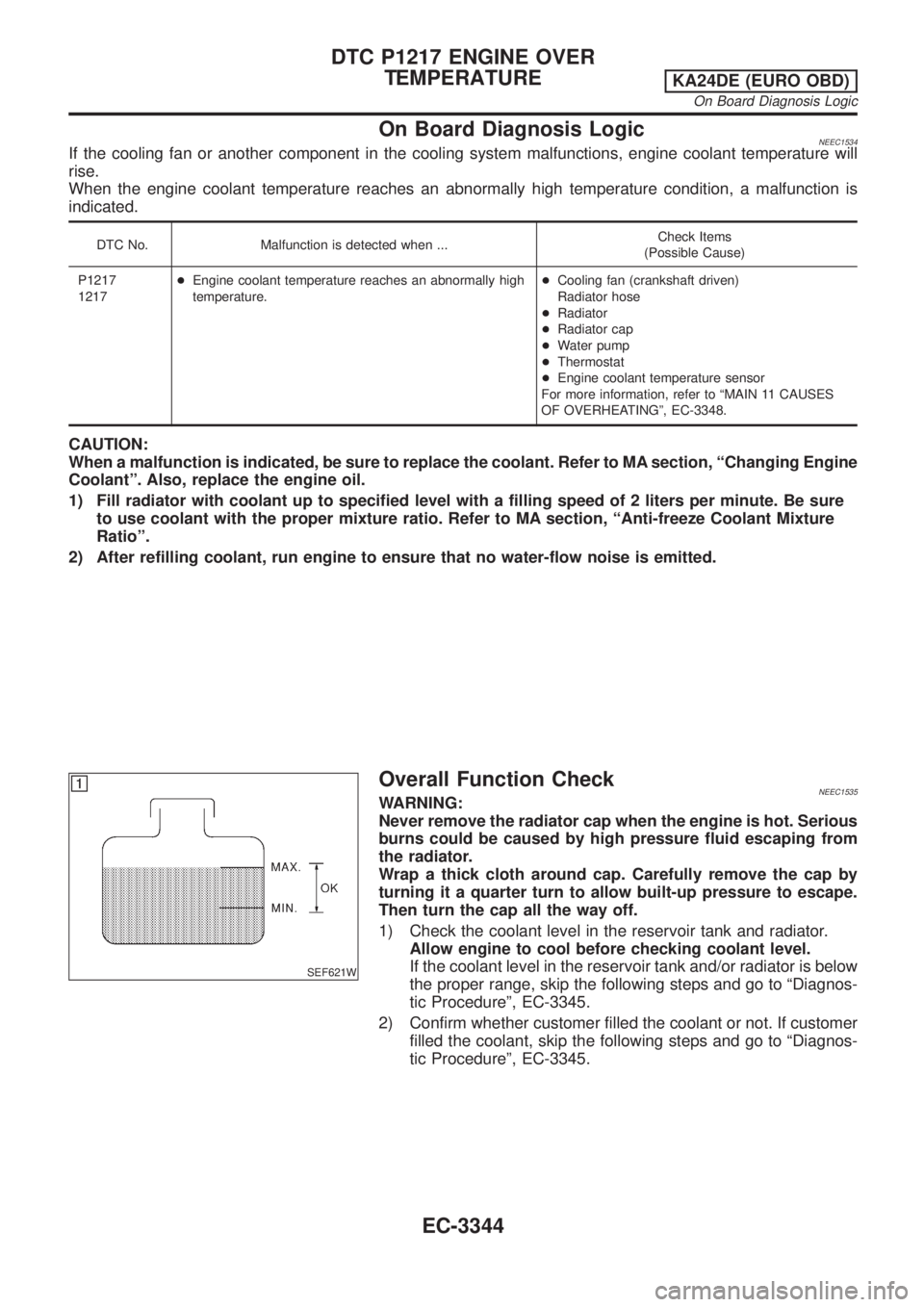
1) Check the coolant level in the reservoir tank and radiator.
Allow engine to cool before checking coolant level.
If the coolant level in the reservoir tank and/or radiator is below
the proper range, skip the following steps and go to ªDiagnos-
tic Procedureº, EC-3345.
2) Confirm whether customer filled the coolant or not. If customer
filled the coolant, skip the following steps and go to ªDiagnos-
tic Procedureº, EC-3345.
DTC P1217 ENGINE OVER
TEMPERATURE
KA24DE (EURO OBD)
On Board Diagnosis Logic
EC-3344
Page 889 of 1306
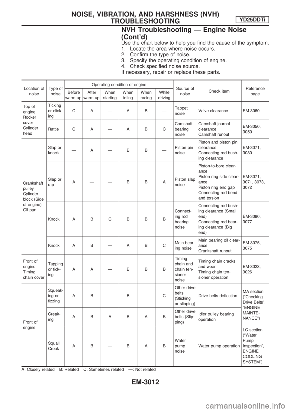
Use the chart below to help you find the cause of the symptom.
1. Locate the area where noise occurs.
2. Confirm the type of noise.
3. Specify the operating condition of engine.
4. Check specified noise source.
If necessary, repair or replace these parts.
Location of
noiseType of
noiseOperating condition of engine
Source of
noiseCheck itemReference
page Before
warm-upAfter
warm-upWhen
startingWhen
idlingWhen
racingWhile
driving
Top of
engine
Rocker
cover
Cylinder
headTicking
or click-
ingCAÐABÐTappet
noiseValve clearance EM-3060
Rattle C A Ð A B CCamshaft
bearing
noiseCamshaft journal
clearance
Camshaft runoutEM-3050,
3050
Crankshaft
pulley
Cylinder
block (Side
of engine)
Oil panSlap or
knockÐAÐB BÐPiston pin
noisePiston and piston pin
clearance
Connecting rod bush-
ing clearanceEM-3071,
3080
Slap or
rapAÐÐBBAPiston slap
noisePiston-to-bore clear-
ance
Piston ring side clear-
ance
Piston ring end gap
Connecting rod bend
and torsionEM-3071,
3071, 3073,
3072
Knock A B C B B BConnect-
ing rod
bearing
noiseConnecting rod bush-
ing clearance (Small
end)
Connecting rod bear-
ing clearance (Big
end)EM-3080,
3077
Knock A B Ð A B CMain bear-
ing noiseMain bearing oil clear-
ance
Crankshaft runoutEM-3075,
3075
Front of
engine
Timing
chain coverTapping
or tick-
ingAAÐBBBTiming
chain and
chain ten-
sioner
noiseTiming chain cracks
and wear
Timing chain ten-
sioner operationEM-3023,
3026
Front of
engineSqueak-
ing or
fizzingABÐBÐCOther drive
belts
(Sticking
or slipping)Drive belts deflectionMA section
(ªChecking
Drive Beltsº,
ªENGINE
MAINTE-
NANCEº) Creak-
ingABABABOther drive
belts (Slip-
ping)Idler pulley bearing
operation
Squall
CreakABÐBABWater
pump
noiseWater pump operationLC section
(ªWater
Pump
Inspectionº,
ENGINE
COOLING
SYSTEMº)
A: Closely related B: Related C: Sometimes related Ð: Not related
NOISE, VIBRATION, AND HARSHNESS (NVH)
TROUBLESHOOTINGYD25DDTi
NVH Troubleshooting Ð Engine Noise
(Cont'd)
EM-3012
Page 921 of 1306
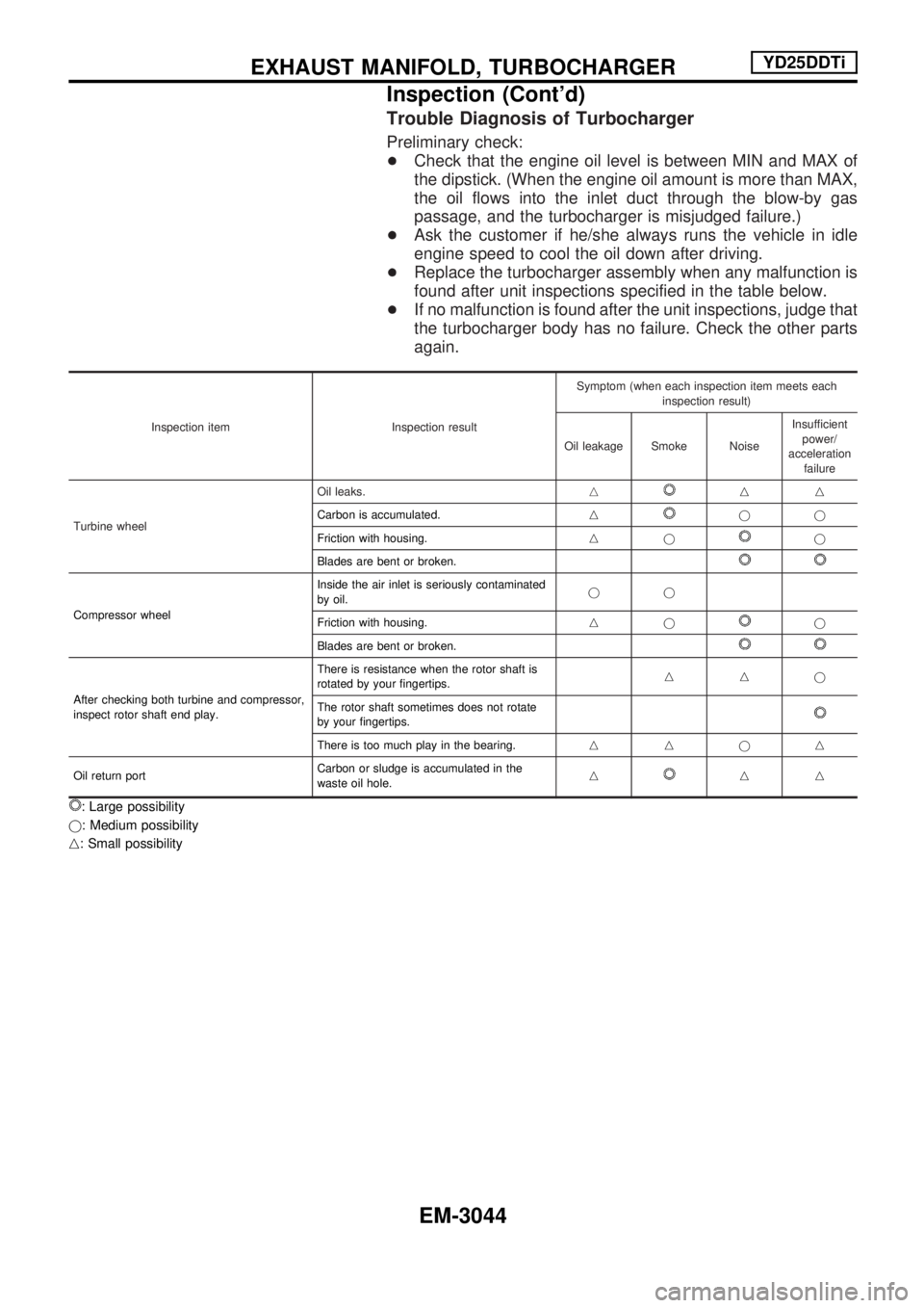
Trouble Diagnosis of Turbocharger
Preliminary check:
+Check that the engine oil level is between MIN and MAX of
the dipstick. (When the engine oil amount is more than MAX,
the oil flows into the inlet duct through the blow-by gas
passage, and the turbocharger is misjudged failure.)
+Ask the customer if he/she always runs the vehicle in idle
engine speed to cool the oil down after driving.
+Replace the turbocharger assembly when any malfunction is
found after unit inspections specified in the table below.
+If no malfunction is found after the unit inspections, judge that
the turbocharger body has no failure. Check the other parts
again.
Inspection item Inspection resultSymptom (when each inspection item meets each
inspection result)
Oil leakage Smoke NoiseInsufficient
power/
acceleration
failure
Turbine wheelOil leaks.n
nn
Carbon is accumulated.n
jj
Friction with housing.nj
j
Blades are bent or broken.
Compressor wheelInside the air inlet is seriously contaminated
by oil.jj
Friction with housing.njj
Blades are bent or broken.
After checking both turbine and compressor,
inspect rotor shaft end play.There is resistance when the rotor shaft is
rotated by your fingertips.nnj
The rotor shaft sometimes does not rotate
by your fingertips.
There is too much play in the bearing.nnjn
Oil return portCarbon or sludge is accumulated in the
waste oil hole.n
nn
: Large possibility
j: Medium possibility
n: Small possibility
EXHAUST MANIFOLD, TURBOCHARGERYD25DDTi
Inspection (Cont'd)
EM-3044
Page 937 of 1306
Valve Clearance
CHECKING
Check valve clearance while engine is cold and not running.
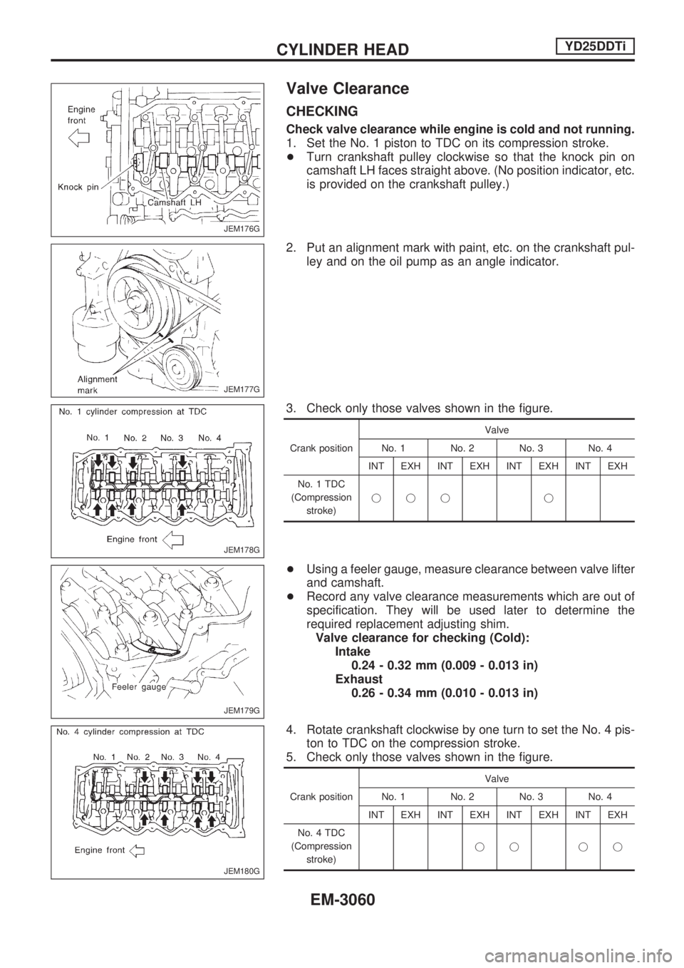
1. Set the No. 1 piston to TDC on its compression stroke.
+Turn crankshaft pulley clockwise so that the knock pin on
camshaft LH faces straight above. (No position indicator, etc.
is provided on the crankshaft pulley.)
2. Put an alignment mark with paint, etc. on the crankshaft pul-
ley and on the oil pump as an angle indicator.
3. Check only those valves shown in the figure.
Crank positionValve
No. 1 No. 2 No. 3 No. 4
INT EXH INT EXH INT EXH INT EXH
No. 1 TDC
(Compression
stroke)jjj j
+Using a feeler gauge, measure clearance between valve lifter
and camshaft.
+Record any valve clearance measurements which are out of
specification. They will be used later to determine the
required replacement adjusting shim.
Valve clearance for checking (Cold):
Intake
0.24 - 0.32 mm (0.009 - 0.013 in)
Exhaust
0.26 - 0.34 mm (0.010 - 0.013 in)
4. Rotate crankshaft clockwise by one turn to set the No. 4 pis-
ton to TDC on the compression stroke.
5. Check only those valves shown in the figure.
Crank positionValve
No. 1 No. 2 No. 3 No. 4
INT EXH INT EXH INT EXH INT EXH
No. 4 TDC
(Compression
stroke)jj jj
JEM176G
JEM177G
JEM178G
JEM179G
JEM180G
CYLINDER HEADYD25DDTi
EM-3060
Page 986 of 1306
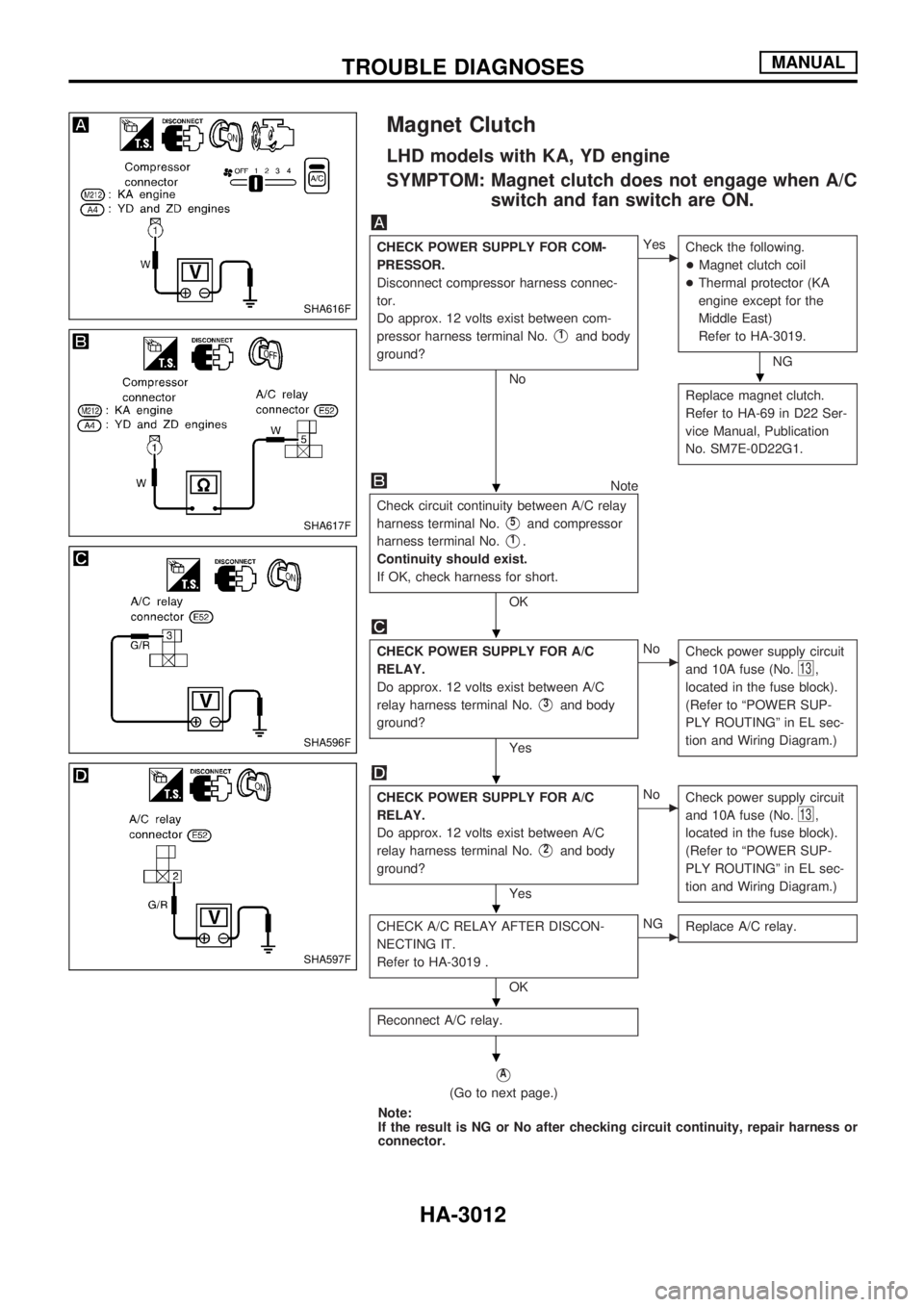
Magnet Clutch
LHD models with KA, YD engine
SYMPTOM: Magnet clutch does not engage when A/C
switch and fan switch are ON.
CHECK POWER SUPPLY FOR COM-
PRESSOR.
Disconnect compressor harness connec-
tor.
Do approx. 12 volts exist between com-
pressor harness terminal No.
V1and body
ground?
No
cYes
Check the following.
+Magnet clutch coil
+Thermal protector (KA
engine except for the
Middle East)
Refer to HA-3019.
NG
Replace magnet clutch.
Refer to HA-69 in D22 Ser-
vice Manual, Publication
No. SM7E-0D22G1.
Note
Check circuit continuity between A/C relay
harness terminal No.
V5and compressor
harness terminal No.
V1.
Continuity should exist.
If OK, check harness for short.
OK
CHECK POWER SUPPLY FOR A/C
RELAY.
Do approx. 12 volts exist between A/C
relay harness terminal No.
V3and body
ground?
Yes
cNo
Check power supply circuit
and 10A fuse (No.
13,
located in the fuse block).
(Refer to ªPOWER SUP-
PLY ROUTINGº in EL sec-
tion and Wiring Diagram.)
CHECK POWER SUPPLY FOR A/C
RELAY.
Do approx. 12 volts exist between A/C
relay harness terminal No.
V2and body
ground?
Yes
cNo
Check power supply circuit
and 10A fuse (No.
13,
located in the fuse block).
(Refer to ªPOWER SUP-
PLY ROUTINGº in EL sec-
tion and Wiring Diagram.)
CHECK A/C RELAY AFTER DISCON-
NECTING IT.
Refer to HA-3019 .
OK
cNG
Replace A/C relay.
Reconnect A/C relay.
VA
(Go to next page.)
Note:
If the result is NG or No after checking circuit continuity, repair harness or
connector.
SHA616F
SHA617F
SHA596F
SHA597F
.
.
.
.
.
.
.
TROUBLE DIAGNOSESMANUAL
HA-3012
Page 987 of 1306
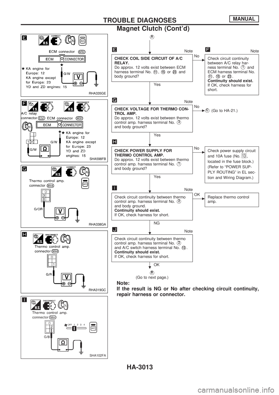
VA
NoteNote
CHECK COIL SIDE CIRCUIT OF A/C
RELAY.
Do approx. 12 volts exist between ECM
harness terminal No.
V11,V15orV23and
body ground?
Yes
cNo
Check circuit continuity
between A/C relay har-
ness terminal No.
V1and
ECM harness terminal No.
V11,V15orV23.
Continuity should exist.
If OK, check harness for
short.
Note
CHECK VOLTAGE FOR THERMO CON-
TROL AMP.
Do approx. 12 volts exist between thermo
control amp. harness terminal No.
V3
and body ground?
Yes
cNoVC(Go to HA-21.)
CHECK POWER SUPPLY FOR
THERMO CONTROL AMP.
Do approx. 12 volts exist between thermo
control amp. harness terminal No.
V1
and body ground?
Yes
cNo
Check power supply circuit
and 10A fuse (No.
13,
located in the fuse block.)
(Refer to ªPOWER SUP-
PLY ROUTINGº in EL sec-
tion and Wiring Diagram.)
Note
Check circuit continuity between thermo
control amp. harness terminal No.
V2
and body ground.
Continuity should exist.
If OK, check harness for short.
NG
cOK
Replace thermo control
amp.
Note
Check circuit continuity between thermo
control amp. harness terminal No.
V2
and A/C switch harness terminal No.V13.
Continuity should exist.
If OK, check harness for short.
OK
VB
(Go to next page.)
Note:
If the result is NG or No after checking circuit continuity,
repair harness or connector.
RHA335GE
SHA598FB
RHA338GA
RHA319GC
SHA102FA
.
.
.
.
.
.
TROUBLE DIAGNOSESMANUAL
Magnet Clutch (Cont'd)
HA-3013
Page 990 of 1306
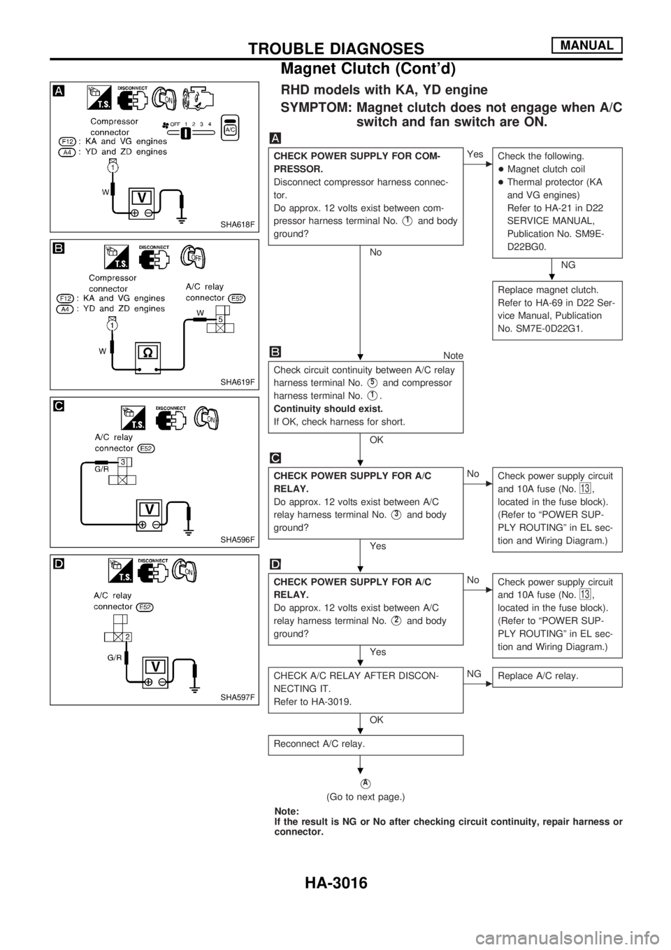
RHD models with KA, YD engine
SYMPTOM: Magnet clutch does not engage when A/C
switch and fan switch are ON.
CHECK POWER SUPPLY FOR COM-
PRESSOR.
Disconnect compressor harness connec-
tor.
Do approx. 12 volts exist between com-
pressor harness terminal No.
V1and body
ground?
No
cYes
Check the following.
+Magnet clutch coil
+Thermal protector (KA
and VG engines)
Refer to HA-21 in D22
SERVICE MANUAL,
Publication No. SM9E-
D22BG0.
NG
Replace magnet clutch.
Refer to HA-69 in D22 Ser-
vice Manual, Publication
No. SM7E-0D22G1.
Note
Check circuit continuity between A/C relay
harness terminal No.
V5and compressor
harness terminal No.
V1.
Continuity should exist.
If OK, check harness for short.
OK
CHECK POWER SUPPLY FOR A/C
RELAY.
Do approx. 12 volts exist between A/C
relay harness terminal No.
V3and body
ground?
Yes
cNo
Check power supply circuit
and 10A fuse (No.
13,
located in the fuse block).
(Refer to ªPOWER SUP-
PLY ROUTINGº in EL sec-
tion and Wiring Diagram.)
CHECK POWER SUPPLY FOR A/C
RELAY.
Do approx. 12 volts exist between A/C
relay harness terminal No.
V2and body
ground?
Yes
cNo
Check power supply circuit
and 10A fuse (No.
13,
located in the fuse block).
(Refer to ªPOWER SUP-
PLY ROUTINGº in EL sec-
tion and Wiring Diagram.)
CHECK A/C RELAY AFTER DISCON-
NECTING IT.
Refer to HA-3019.
OK
cNG
Replace A/C relay.
Reconnect A/C relay.
VA
(Go to next page.)
Note:
If the result is NG or No after checking circuit continuity, repair harness or
connector.
SHA618F
SHA619F
SHA596F
SHA597F
.
.
.
.
.
.
.
TROUBLE DIAGNOSESMANUAL
Magnet Clutch (Cont'd)
HA-3016
Page 991 of 1306
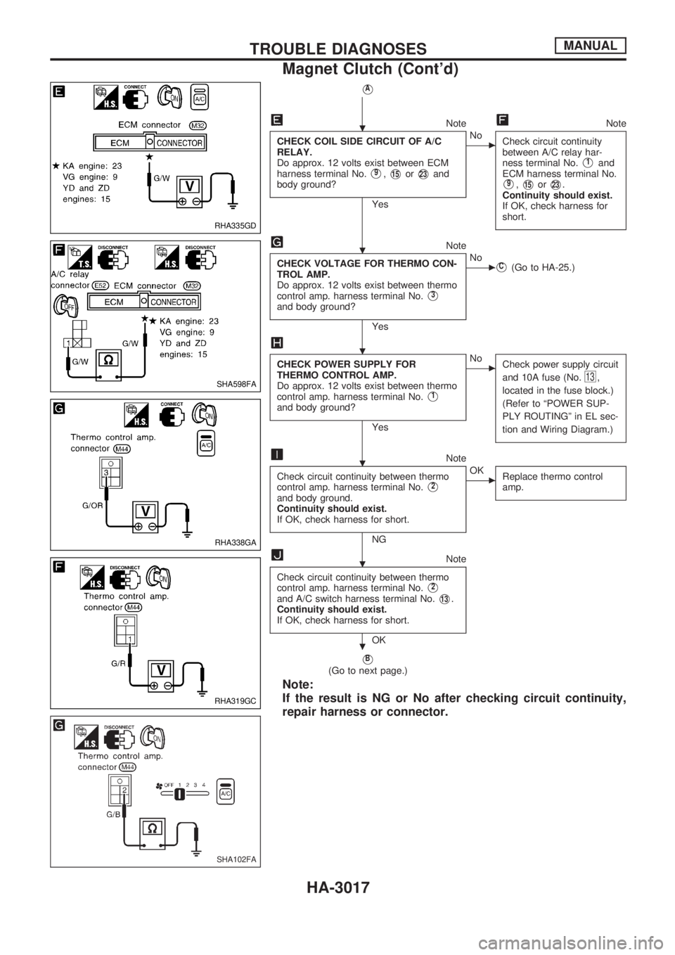
VA
NoteNote
CHECK COIL SIDE CIRCUIT OF A/C
RELAY.
Do approx. 12 volts exist between ECM
harness terminal No.
V9,V15orV23and
body ground?
Yes
cNo
Check circuit continuity
between A/C relay har-
ness terminal No.
V1and
ECM harness terminal No.
V9,V15orV23.
Continuity should exist.
If OK, check harness for
short.
Note
CHECK VOLTAGE FOR THERMO CON-
TROL AMP.
Do approx. 12 volts exist between thermo
control amp. harness terminal No.
V3
and body ground?
Yes
cNoVC(Go to HA-25.)
CHECK POWER SUPPLY FOR
THERMO CONTROL AMP.
Do approx. 12 volts exist between thermo
control amp. harness terminal No.
V1
and body ground?
Yes
cNo
Check power supply circuit
and 10A fuse (No.
13,
located in the fuse block.)
(Refer to ªPOWER SUP-
PLY ROUTINGº in EL sec-
tion and Wiring Diagram.)
Note
Check circuit continuity between thermo
control amp. harness terminal No.
V2
and body ground.
Continuity should exist.
If OK, check harness for short.
NG
cOK
Replace thermo control
amp.
Note
Check circuit continuity between thermo
control amp. harness terminal No.
V2
and A/C switch harness terminal No.V13.
Continuity should exist.
If OK, check harness for short.
OK
VB
(Go to next page.)
Note:
If the result is NG or No after checking circuit continuity,
repair harness or connector.
RHA335GD
SHA598FA
RHA338GA
RHA319GC
SHA102FA
.
.
.
.
.
.
TROUBLE DIAGNOSESMANUAL
Magnet Clutch (Cont'd)
HA-3017