2001 NISSAN PICK-UP warning lights
[x] Cancel search: warning lightsPage 86 of 1306
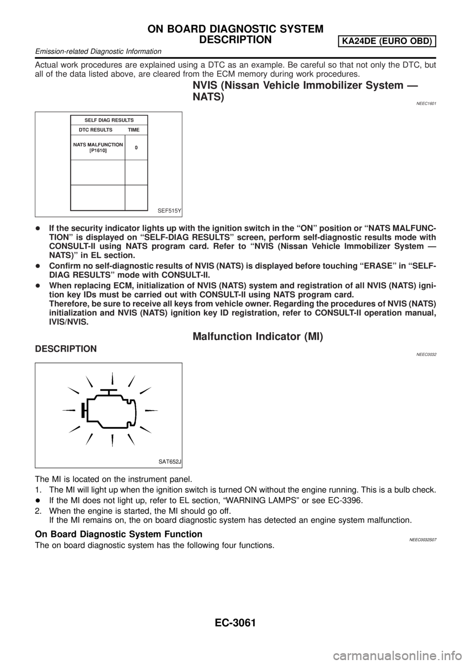
Actual work procedures are explained using a DTC as an example. Be careful so that not only the DTC, but
all of the data listed above, are cleared from the ECM memory during work procedures.
NVIS (Nissan Vehicle Immobilizer System Ð
NATS)
NEEC1601
SEF515Y
+If the security indicator lights up with the ignition switch in the ªONº position or ªNATS MALFUNC-
TIONº is displayed on ªSELF-DIAG RESULTSº screen, perform self-diagnostic results mode with
CONSULT-II using NATS program card. Refer to ªNVIS (Nissan Vehicle Immobilizer System Ð
NATS)º in EL section.
+Confirm no self-diagnostic results of NVIS (NATS) is displayed before touching ªERASEº in ªSELF-
DIAG RESULTSº mode with CONSULT-II.
+When replacing ECM, initialization of NVIS (NATS) system and registration of all NVIS (NATS) igni-
tion key IDs must be carried out with CONSULT-II using NATS program card.
Therefore, be sure to receive all keys from vehicle owner. Regarding the procedures of NVIS (NATS)
initialization and NVIS (NATS) ignition key ID registration, refer to CONSULT-II operation manual,
IVIS/NVIS.
Malfunction Indicator (MI)
DESCRIPTIONNEEC0032
SAT652J
The MI is located on the instrument panel.
1. The MI will light up when the ignition switch is turned ON without the engine running. This is a bulb check.
+If the MI does not light up, refer to EL section, ªWARNING LAMPSº or see EC-3396.
2. When the engine is started, the MI should go off.
If the MI remains on, the on board diagnostic system has detected an engine system malfunction.
On Board Diagnostic System FunctionNEEC0032S07The on board diagnostic system has the following four functions.
ON BOARD DIAGNOSTIC SYSTEM
DESCRIPTION
KA24DE (EURO OBD)
Emission-related Diagnostic Information
EC-3061
Page 454 of 1306
+Erasing the emission-related diagnostic information using CONSULT-II is easier and quicker than
switching the diagnostic test mode using the data link connector.
NATS (Nissan Anti-Theft System)
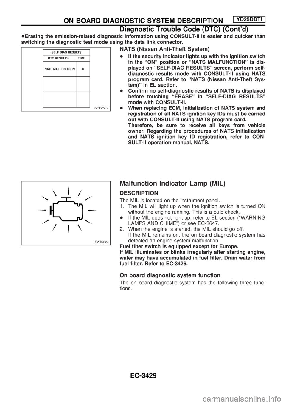
+If the security indicator lights up with the ignition switch
in the ªONº position or ªNATS MALFUNCTIONº is dis-
played on ªSELF-DIAG RESULTSº screen, perform self-
diagnostic results mode with CONSULT-II using NATS
program card. Refer to ªNATS (Nissan Anti-Theft Sys-
tem)º in EL section.
+Confirm no self-diagnostic results of NATS is displayed
before touching ªERASEº in ªSELF-DIAG RESULTSº
mode with CONSULT-II.
+When replacing ECM, initialization of NATS system and
registration of all NATS ignition key IDs must be carried
out with CONSULT-II using NATS program card.
Therefore, be sure to receive all keys from vehicle
owner. Regarding the procedures of NATS initialization
and NATS ignition key ID registration, refer to CON-
SULT-II operation manual, NATS.
Malfunction Indicator Lamp (MIL)
DESCRIPTION
The MIL is located on the instrument panel.
1. The MIL will light up when the ignition switch is turned ON
without the engine running. This is a bulb check.
+If the MIL does not light up, refer to EL section (ªWARNING
LAMPS AND CHIMEº) or see EC-3647.
2. When the engine is started, the MIL should go off.
If the MIL remains on, the on board diagnostic system has
detected an engine system malfunction.
Fuel filter switch is equipped except for Europe.
If MIL illuminates or blinks irregularly after starting engine,
water may have accumulated in fuel filter. Drain water from
fuel filter. Refer to EC-3426.
On board diagnostic system function
The on board diagnostic system has the following three func-
tions.
SEF252Z
SAT652J
ON BOARD DIAGNOSTIC SYSTEM DESCRIPTIONYD25DDTi
Diagnostic Trouble Code (DTC) (Cont'd)
EC-3429
Page 1086 of 1306
HOW TO CHANGE SELF-DIAGNOSIS MODE
With CONSULT-II
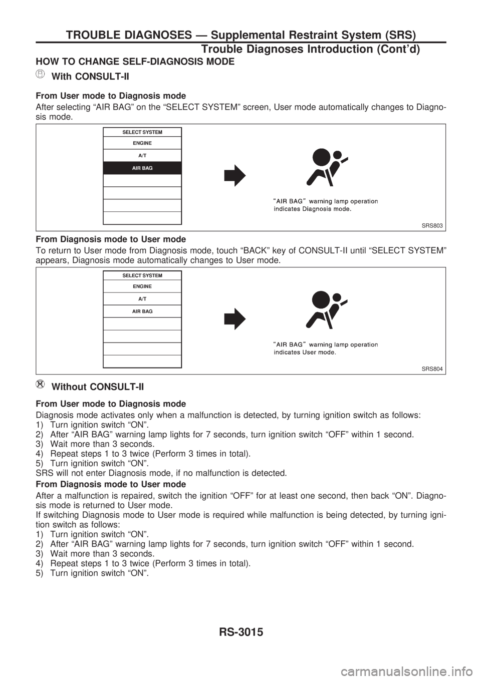
From User mode to Diagnosis mode
After selecting ªAIR BAGº on the ªSELECT SYSTEMº screen, User mode automatically changes to Diagno-
sis mode.
From Diagnosis mode to User mode
To return to User mode from Diagnosis mode, touch ªBACKº key of CONSULT-II until ªSELECT SYSTEMº
appears, Diagnosis mode automatically changes to User mode.
Without CONSULT-II
From User mode to Diagnosis mode
Diagnosis mode activates only when a malfunction is detected, by turning ignition switch as follows:
1) Turn ignition switch ªONº.
2) After ªAIR BAGº warning lamp lights for 7 seconds, turn ignition switch ªOFFº within 1 second.
3) Wait more than 3 seconds.
4) Repeat steps 1 to 3 twice (Perform 3 times in total).
5) Turn ignition switch ªONº.
SRS will not enter Diagnosis mode, if no malfunction is detected.
From Diagnosis mode to User mode
After a malfunction is repaired, switch the ignition ªOFFº for at least one second, then back ªONº. Diagno-
sis mode is returned to User mode.
If switching Diagnosis mode to User mode is required while malfunction is being detected, by turning igni-
tion switch as follows:
1) Turn ignition switch ªONº.
2) After ªAIR BAGº warning lamp lights for 7 seconds, turn ignition switch ªOFFº within 1 second.
3) Wait more than 3 seconds.
4) Repeat steps 1 to 3 twice (Perform 3 times in total).
5) Turn ignition switch ªONº.
SRS803
SRS804
TROUBLE DIAGNOSES Ð Supplemental Restraint System (SRS)
Trouble Diagnoses Introduction (Cont'd)
RS-3015
Page 1095 of 1306
DIGNOSTIC PROCEDURE 3 (without CONSULT-II)
Inspecting SRS malfunctioning parts by using ªAIR BAGº
warning lamp Ð Diagnosis mode
NOTE:
SRS will not enter Diagnosis mode if no malfunction is
detected in User mode.
1. Turn ignition switch ªONº.
2. After ªAIR BAGº warning lamp lights for 7 seconds, turn igni-
tion switch ªOFFº within 1 second.
3. Wait more than 3 seconds.
4. Repeat steps 1 to 3 twice (Perform 3 times in total).
5. Turn ignition switch ªONº.
SRS is now in Diagnosis mode.
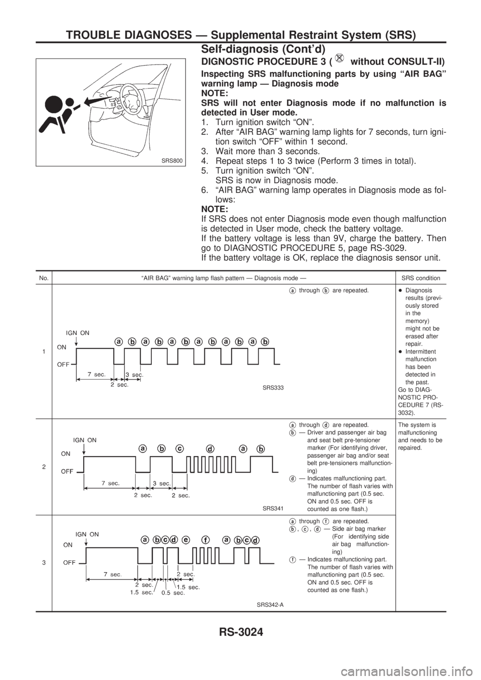
6. ªAIR BAGº warning lamp operates in Diagnosis mode as fol-
lows:
NOTE:
If SRS does not enter Diagnosis mode even though malfunction
is detected in User mode, check the battery voltage.
If the battery voltage is less than 9V, charge the battery. Then
go to DIAGNOSTIC PROCEDURE 5, page RS-3029.
If the battery voltage is OK, replace the diagnosis sensor unit.
No. ªAIR BAGº warning lamp flash pattern Ð Diagnosis mode Ð SRS condition
1
SRS333
VathroughVbare repeated.+Diagnosis
results (previ-
ously stored
in the
memory)
might not be
erased after
repair.
+Intermittent
malfunction
has been
detected in
the past.
Go to DIAG-
NOSTIC PRO-
CEDURE 7 (RS-
3032).
2
SRS341
VathroughVdare repeated.
VbÐ Driver and passenger air bag
and seat belt pre-tensioner
marker (For identifying driver,
passenger air bag and/or seat
belt pre-tensioners malfunction-
ing)
VdÐ Indicates malfunctioning part.
The number of flash varies with
malfunctioning part (0.5 sec.
ON and 0.5 sec. OFF is
counted as one flash.)The system is
malfunctioning
and needs to be
repaired.
3
SRS342-A
VathroughVfare repeated.
Vb,Vc,VdÐ Side air bag marker
(For identifying side
air bag malfunction-
ing)
VfÐ Indicates malfunctioning part.
The number of flash varies with
malfunctioning part (0.5 sec.
ON and 0.5 sec. OFF is
counted as one flash.)
SRS800
TROUBLE DIAGNOSES Ð Supplemental Restraint System (SRS)
Self-diagnosis (Cont'd)
RS-3024
Page 1102 of 1306
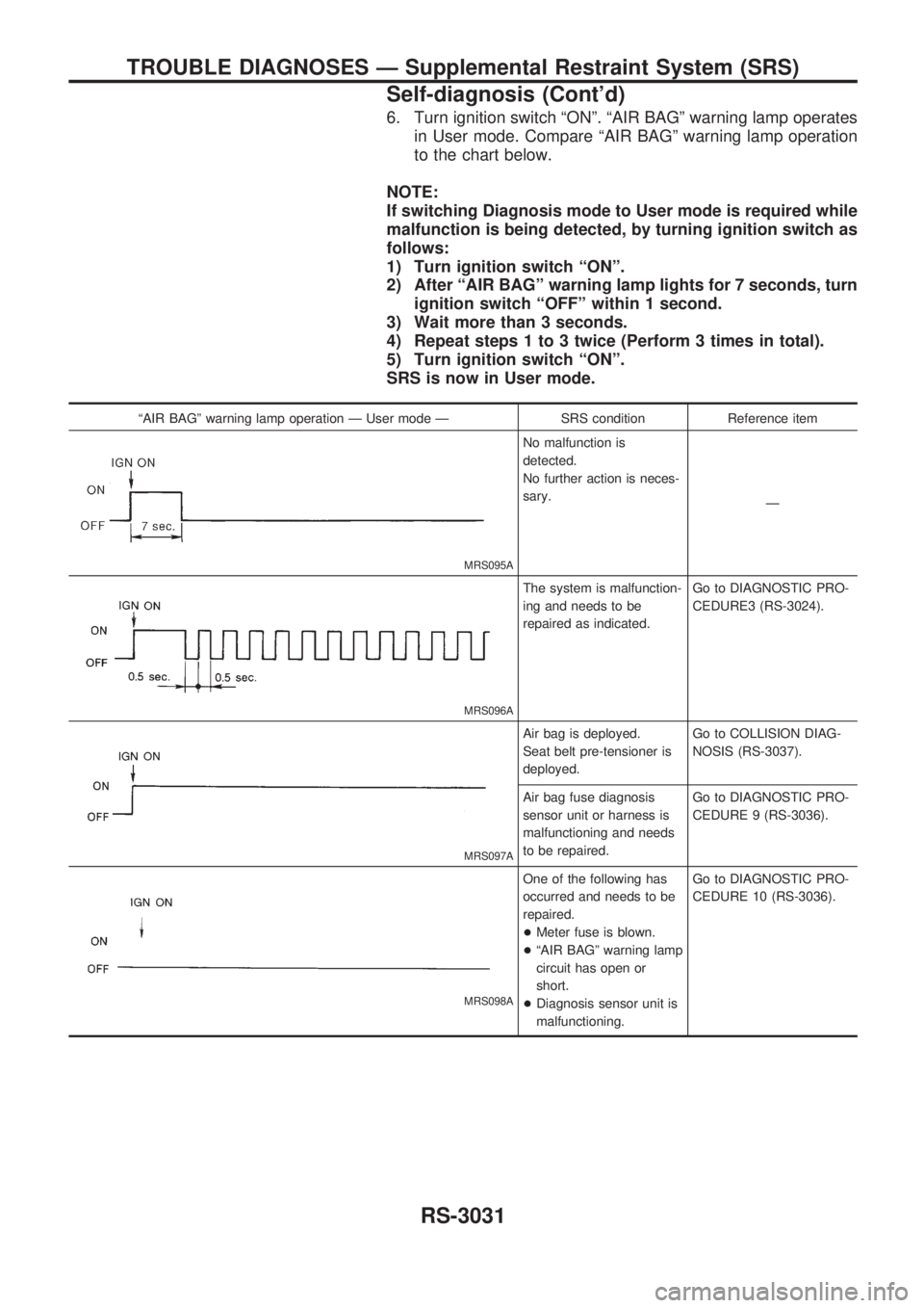
6. Turn ignition switch ªONº. ªAIR BAGº warning lamp operates
in User mode. Compare ªAIR BAGº warning lamp operation
to the chart below.
NOTE:
If switching Diagnosis mode to User mode is required while
malfunction is being detected, by turning ignition switch as
follows:
1) Turn ignition switch ªONº.
2) After ªAIR BAGº warning lamp lights for 7 seconds, turn
ignition switch ªOFFº within 1 second.
3) Wait more than 3 seconds.
4) Repeat steps 1 to 3 twice (Perform 3 times in total).
5) Turn ignition switch ªONº.
SRS is now in User mode.
ªAIR BAGº warning lamp operation Ð User mode Ð SRS condition Reference item
MRS095A
No malfunction is
detected.
No further action is neces-
sary.
Ð
MRS096A
The system is malfunction-
ing and needs to be
repaired as indicated.Go to DIAGNOSTIC PRO-
CEDURE3 (RS-3024).
MRS097A
Air bag is deployed.
Seat belt pre-tensioner is
deployed.Go to COLLISION DIAG-
NOSIS (RS-3037).
Air bag fuse diagnosis
sensor unit or harness is
malfunctioning and needs
to be repaired.Go to DIAGNOSTIC PRO-
CEDURE 9 (RS-3036).
MRS098A
One of the following has
occurred and needs to be
repaired.
+Meter fuse is blown.
+ªAIR BAGº warning lamp
circuit has open or
short.
+Diagnosis sensor unit is
malfunctioning.Go to DIAGNOSTIC PRO-
CEDURE 10 (RS-3036).
TROUBLE DIAGNOSES Ð Supplemental Restraint System (SRS)
Self-diagnosis (Cont'd)
RS-3031