Page 87 of 1306

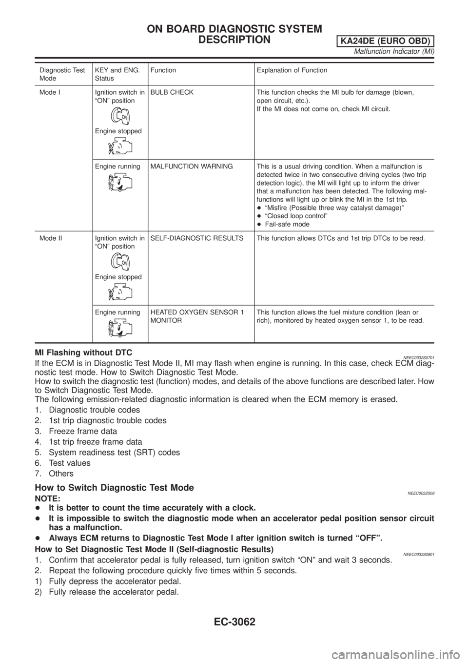
Diagnostic Test
ModeKEY and ENG.
StatusFunction Explanation of Function
Mode I Ignition switch in
ªONº position
Engine stopped
BULB CHECK This function checks the MI bulb for damage (blown,
open circuit, etc.).
If the MI does not come on, check MI circuit.
Engine running
MALFUNCTION WARNING This is a usual driving condition. When a malfunction is
detected twice in two consecutive driving cycles (two trip
detection logic), the MI will light up to inform the driver
that a malfunction has been detected. The following mal-
functions will light up or blink the MI in the 1st trip.
+ªMisfire (Possible three way catalyst damage)º
+ªClosed loop controlº
+Fail-safe mode
Mode II Ignition switch in
ªONº position
Engine stopped
SELF-DIAGNOSTIC RESULTS This function allows DTCs and 1st trip DTCs to be read.
Engine running
HEATED OXYGEN SENSOR 1
MONITORThis function allows the fuel mixture condition (lean or
rich), monitored by heated oxygen sensor 1, to be read.
MI Flashing without DTCNEEC0032S0701If the ECM is in Diagnostic Test Mode II, MI may flash when engine is running. In this case, check ECM diag-
nostic test mode. How to Switch Diagnostic Test Mode.
How to switch the diagnostic test (function) modes, and details of the above functions are described later. How
to Switch Diagnostic Test Mode.
The following emission-related diagnostic information is cleared when the ECM memory is erased.
1. Diagnostic trouble codes
2. 1st trip diagnostic trouble codes
3. Freeze frame data
4. 1st trip freeze frame data
5. System readiness test (SRT) codes
6. Test values
7. Others
How to Switch Diagnostic Test ModeNEEC0032S08NOTE:
+It is better to count the time accurately with a clock.
+It is impossible to switch the diagnostic mode when an accelerator pedal position sensor circuit
has a malfunction.
+Always ECM returns to Diagnostic Test Mode I after ignition switch is turned ªOFFº.
How to Set Diagnostic Test Mode II (Self-diagnostic Results)
NEEC0032S08011. Confirm that accelerator pedal is fully released, turn ignition switch ªONº and wait 3 seconds.
2. Repeat the following procedure quickly five times within 5 seconds.
1) Fully depress the accelerator pedal.
2) Fully release the accelerator pedal.
ON BOARD DIAGNOSTIC SYSTEM
DESCRIPTION
KA24DE (EURO OBD)
Malfunction Indicator (MI)
EC-3062
Page 899 of 1306

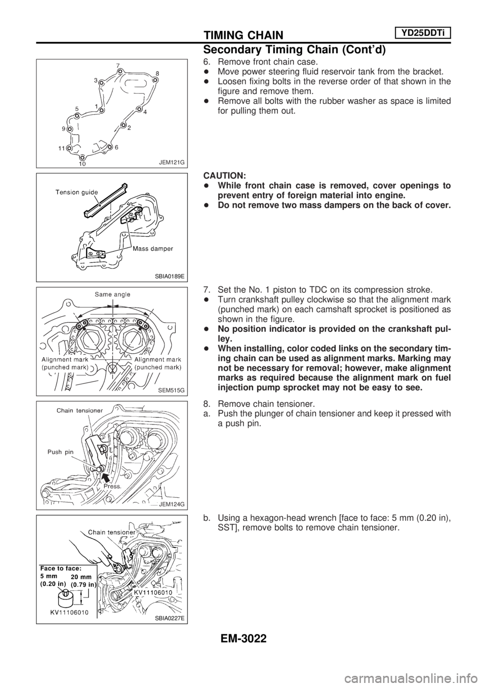
6. Remove front chain case.
+Move power steering fluid reservoir tank from the bracket.
+Loosen fixing bolts in the reverse order of that shown in the
figure and remove them.
+Remove all bolts with the rubber washer as space is limited
for pulling them out.
CAUTION:
+While front chain case is removed, cover openings to
prevent entry of foreign material into engine.
+Do not remove two mass dampers on the back of cover.
7. Set the No. 1 piston to TDC on its compression stroke.
+Turn crankshaft pulley clockwise so that the alignment mark
(punched mark) on each camshaft sprocket is positioned as
shown in the figure.
+No position indicator is provided on the crankshaft pul-
ley.
+When installing, color coded links on the secondary tim-
ing chain can be used as alignment marks. Marking may
not be necessary for removal; however, make alignment
marks as required because the alignment mark on fuel
injection pump sprocket may not be easy to see.
8. Remove chain tensioner.
a. Push the plunger of chain tensioner and keep it pressed with
a push pin.
b. Using a hexagon-head wrench [face to face: 5 mm (0.20 in),
SST], remove bolts to remove chain tensioner.
JEM121G
SBIA0189E
SEM515G
JEM124G
SBIA0227E
TIMING CHAINYD25DDTi
Secondary Timing Chain (Cont'd)
EM-3022
Page 937 of 1306

Valve Clearance
CHECKING
Check valve clearance while engine is cold and not running.
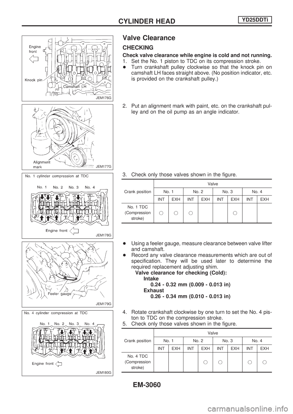
1. Set the No. 1 piston to TDC on its compression stroke.
+Turn crankshaft pulley clockwise so that the knock pin on
camshaft LH faces straight above. (No position indicator, etc.
is provided on the crankshaft pulley.)
2. Put an alignment mark with paint, etc. on the crankshaft pul-
ley and on the oil pump as an angle indicator.
3. Check only those valves shown in the figure.
Crank positionValve
No. 1 No. 2 No. 3 No. 4
INT EXH INT EXH INT EXH INT EXH
No. 1 TDC
(Compression
stroke)jjj j
+Using a feeler gauge, measure clearance between valve lifter
and camshaft.
+Record any valve clearance measurements which are out of
specification. They will be used later to determine the
required replacement adjusting shim.
Valve clearance for checking (Cold):
Intake
0.24 - 0.32 mm (0.009 - 0.013 in)
Exhaust
0.26 - 0.34 mm (0.010 - 0.013 in)
4. Rotate crankshaft clockwise by one turn to set the No. 4 pis-
ton to TDC on the compression stroke.
5. Check only those valves shown in the figure.
Crank positionValve
No. 1 No. 2 No. 3 No. 4
INT EXH INT EXH INT EXH INT EXH
No. 4 TDC
(Compression
stroke)jj jj
JEM176G
JEM177G
JEM178G
JEM179G
JEM180G
CYLINDER HEADYD25DDTi
EM-3060