2001 NISSAN PICK-UP steering wheel
[x] Cancel search: steering wheelPage 33 of 1306
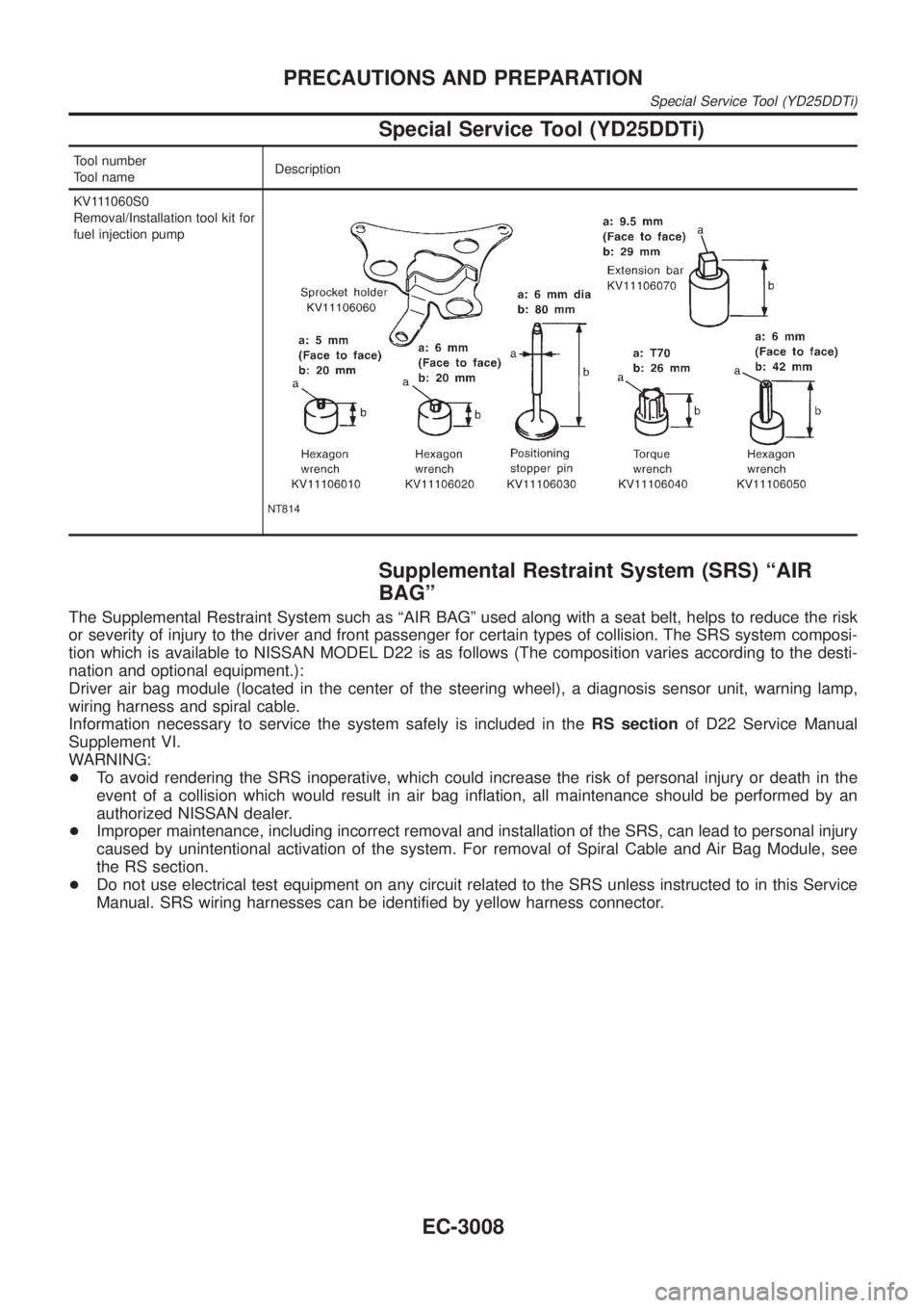
Special Service Tool (YD25DDTi)
Tool number
Tool nameDescription
KV111060S0
Removal/Installation tool kit for
fuel injection pump
NT814
Supplemental Restraint System (SRS) ªAIR
BAGº
The Supplemental Restraint System such as ªAIR BAGº used along with a seat belt, helps to reduce the risk
or severity of injury to the driver and front passenger for certain types of collision. The SRS system composi-
tion which is available to NISSAN MODEL D22 is as follows (The composition varies according to the desti-
nation and optional equipment.):
Driver air bag module (located in the center of the steering wheel), a diagnosis sensor unit, warning lamp,
wiring harness and spiral cable.
Information necessary to service the system safely is included in theRS sectionof D22 Service Manual
Supplement VI.
WARNING:
+To avoid rendering the SRS inoperative, which could increase the risk of personal injury or death in the
event of a collision which would result in air bag inflation, all maintenance should be performed by an
authorized NISSAN dealer.
+Improper maintenance, including incorrect removal and installation of the SRS, can lead to personal injury
caused by unintentional activation of the system. For removal of Spiral Cable and Air Bag Module, see
the RS section.
+Do not use electrical test equipment on any circuit related to the SRS unless instructed to in this Service
Manual. SRS wiring harnesses can be identified by yellow harness connector.
PRECAUTIONS AND PREPARATION
Special Service Tool (YD25DDTi)
EC-3008
Page 37 of 1306
Supplemental Restraint System (SRS) ªAIR
BAGº and ªSEAT BELT PRE-TENSIONERº
NEEC0002The Supplemental Restraint System such as ªAIR BAGº and ªSEAT BELT PRE-TENSIONERº used along with
a seat belt, helps to reduce the risk or severity of injury to the driver and front passenger in a frontal collision.
The SRS system composition which is available to NISSAN MODEL D22 is as follows (The composition var-
ies according to the destination and optional equipment.):
Driver air bag module (located in the center of the steering wheel), front passenger air bag module (located
on the instrument panel on passenger side), seat belt pre-tensioner, a diagnosis sensor unit, warning lamp,
wiring harness and spiral cable.
Information necessary to service the system safely is included in theRS sectionof this Service Manual.
WARNING:
+To avoid rendering the SRS inoperative, which could increase the risk of personal injury or death
in the event of a collision which would result in air bag inflation, all maintenance must be performed
by an authorized NISSAN dealer.
+Improper maintenance, including incorrect removal and installation of the SRS, can lead to per-
sonal injury caused by unintentional activation of the system. For removal of Spiral Cable and Air
Bag Module, see the RS section.
+Do not use electrical test equipment on any circuit related to the SRS unless instructed to in this
Service Manual. SRS wiring harnesses can be identified by yellow harness connector.
Precautions for On Board Diagnostic (OBD)
System of Engine
NEEC0003The ECM has an on board diagnostic system. It will light up the malfunction indicator (MI) to warn the driver
of a malfunction causing emission deterioration.
CAUTION:
+Be sure to turn the ignition switch OFF and disconnect the negative battery terminal before any
repair or inspection work. The open/short circuit of related switches, sensors, solenoid valves, etc.
will cause the MI to light up.
+Be sure to connect and lock the connectors securely after work. A loose (unlocked) connector will
cause the MI to light up due to the open circuit. (Be sure the connector is free from water, grease,
dirt, bent terminals, etc.)
+Certain systems and components, especially those related to OBD, may use a new style slide-
locking type harness connector.
For description and how to disconnect, refer to EL section, ªHARNESS CONNECTORº.
+Be sure to route and secure the harnesses properly after work. The interference of the harness with
a bracket, etc. may cause the MI to light up due to the short circuit.
+Be sure to connect rubber tubes properly after work. A misconnected or disconnected rubber tube
may cause the MI to light up due to the malfunction of the fuel injection system, etc.
+Be sure to erase the unnecessary malfunction information (repairs completed) from the ECM before
returning the vehicle to the customer.
PRECAUTIONSKA24DE (EURO OBD)
Supplemental Restraint System (SRS) ªAIR BAGº and ªSEAT BELT PRE-TENSIONERº
EC-3012
Page 111 of 1306

Basic InspectionNEEC0038Precaution:
Perform Basic Inspection without electrical or mechanical
loads applied;
+Headlamp switch is OFF,
+Air conditioner switch is OFF,
+Rear window defogger switch is OFF,
+Steering wheel is in the straight-ahead position, etc.
1 INSPECTION START
1. Check service records for any recent repairs that may indicate a related problem, or the current need for scheduled
maintenance.
2. Open engine hood and check the following:
+Harness connectors for improper connections
+Vacuum hoses for splits, kinks, or improper connections
+Wiring for improper connections, pinches, or cuts
SEF142I
With CONSULT-II©GO TO 2.
With GST©GO TO 4.
No tools©GO TO 5.
2 CONNECT CONSULT-II TO THE VEHICLE
Connect ªCONSULT-IIº to the data link connector and select ªENGINEº from the menu. Refer to EC-3070.
SEC305D
©GO TO 3.
TROUBLE DIAGNOSIS Ð BASIC
INSPECTION
KA24DE (EURO OBD)
Basic Inspection
EC-3086
Page 131 of 1306
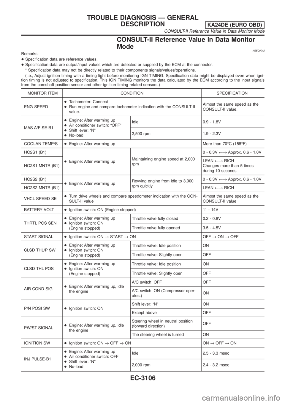
CONSULT-II Reference Value in Data Monitor
Mode
NEEC0042Remarks:
+Specification data are reference values.
+Specification data are output/input values which are detected or supplied by the ECM at the connector.
* Specification data may not be directly related to their components signals/values/operations.
(i.e., Adjust ignition timing with a timing light before monitoring IGN TIMING. Specification data might be displayed even when igni-
tion timing is not adjusted to specification. This IGN TIMING monitors the data calculated by the ECM according to the input signals
from the camshaft position sensor and other ignition timing related sensors.)
MONITOR ITEM CONDITION SPECIFICATION
ENG SPEED+Tachometer: Connect
+Run engine and compare tachometer indication with the CONSULT-II
value.Almost the same speed as the
CONSULT-II value.
MAS A/F SE-B1+Engine: After warming up
+Air conditioner switch: ªOFFº
+Shift lever: ªNº
+No-loadIdle 0.9 - 1.8V
2,500 rpm 1.9 - 2.3V
COOLAN TEMP/S+Engine: After warming up More than 70ÉC (158ÉF)
HO2S1 (B1)
+Engine: After warming upMaintaining engine speed at 2,000
rpm0 - 0.3V¨Approx. 0.6 - 1.0V
HO2S1 MNTR (B1)LEAN¨RICH
Changes more than 5 times
during 10 seconds.
HO2S2 (B1)
+Engine: After warming upRevving engine from idle to 3,000
rpm quickly0 - 0.3V¨Approx. 0.6 - 1.0V
HO2S2 MNTR (B1)LEAN¨RICH
VHCL SPEED SE+Turn drive wheels and compare speedometer indication with the CON-
SULT-II valueAlmost the same speed as the
CONSULT-II value
BATTERY VOLT+Ignition switch: ON (Engine stopped) 11 - 14V
THRTL POS SEN+Engine: After warming up
+Ignition switch: ON
(Engine stopped)Throttle valve fully closed 0.2 - 0.8V
Throttle valve fully opened 3.5 - 4.5V
START SIGNAL+Ignition switch: ON®START®ON OFF®ON®OFF
CLSD THL/P SW+Engine: After warming up
+Ignition switch: ON
(Engine stopped)Throttle valve: Idle position ON
Throttle valve: Slightly open OFF
CLSD THL POS+Engine: After warming up
+Ignition switch: ON
(Engine stopped)Throttle valve: Idle position ON
Throttle valve: Slightly open OFF
AIR COND SIG+Engine: After warming up, idle
the engineA/C switch: OFF OFF
A/C switch: ON (Compressor oper-
ates.)ON
P/N POSI SW+Ignition switch: ONShift lever: ªNº ON
Except above OFF
PW/ST SIGNAL+Engine: After warming up, idle
the engineSteering wheel in neutral position
(forward direction)OFF
The steering wheel is turned ON
IGNITION SW+Ignition switch: ON®OFF®ON ON®OFF®ON
INJ PULSE-B1+Engine: After warming up
+Air conditioner switch: OFF
+Shift lever: ªNº
+No-loadIdle 2.5 - 3.3 msec
2,000 rpm 2.4 - 3.2 msec
TROUBLE DIAGNOSIS Ð GENERAL
DESCRIPTION
KA24DE (EURO OBD)
CONSULT-II Reference Value in Data Monitor Mode
EC-3106
Page 139 of 1306
![NISSAN PICK-UP 2001 Repair Manual TERMI-
NAL
NO.WIRE
COLORITEM CONDITION DATA (DC Voltage)
23 G Throttle position sensor[Ignition switch ON]
+Warm-up condition
+Accelerator pedal fully released0.2 - 0.8V
[Ignition switch ON]
+Accelera NISSAN PICK-UP 2001 Repair Manual TERMI-
NAL
NO.WIRE
COLORITEM CONDITION DATA (DC Voltage)
23 G Throttle position sensor[Ignition switch ON]
+Warm-up condition
+Accelerator pedal fully released0.2 - 0.8V
[Ignition switch ON]
+Accelera](/manual-img/5/57372/w960_57372-138.png)
TERMI-
NAL
NO.WIRE
COLORITEM CONDITION DATA (DC Voltage)
23 G Throttle position sensor[Ignition switch ON]
+Warm-up condition
+Accelerator pedal fully released0.2 - 0.8V
[Ignition switch ON]
+Accelerator pedal fully depressed3.5 - 4.5V
24 W/L Ignition switch[Ignition switch OFF]0V
[Ignition switch ON]BATTERY VOLTAGE
(11 - 14V)
25 B ECM ground[Engine is running]
+Idle speedEngine ground
28 LG/BThrottle position switch
(Closed position)[Ignition switch ON]
+Warm-up condition
+Accelerator pedal releasedBATTERY VOLTAGE
(11 - 14V)
[Ignition switch ON]
+Accelerator pedal depressedApproximately 0V
29 W/L Vehicle speed sensor[Engine is running]
+Lift up the vehicle
+In 2nd gear position
+40 km/h (25 MPH)1-4V
SEF111V
32 B ECM ground[Engine is running]
+Idle speedEngine ground
39 SBPower steering oil
pressure switch[Engine is running]
+Steering wheel is fully turnedApproximately 0V
[Engine is running]
+Steering wheel is not turnedApproximately 5V
42 G/B Sensors' power supply[Ignition switch ON]Approximately 5V
43 B Sensors' ground[Engine is running]
+Idle speedApproximately 0V
TROUBLE DIAGNOSIS Ð GENERAL
DESCRIPTION
KA24DE (EURO OBD)
ECM Terminals and Reference Value
EC-3114
Page 144 of 1306
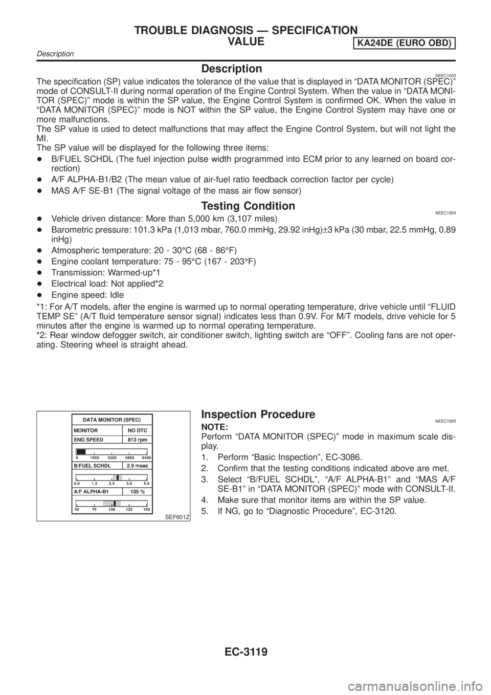
DescriptionNEEC1003The specification (SP) value indicates the tolerance of the value that is displayed in ªDATA MONITOR (SPEC)º
mode of CONSULT-II during normal operation of the Engine Control System. When the value in ªDATA MONI-
TOR (SPEC)º mode is within the SP value, the Engine Control System is confirmed OK. When the value in
ªDATA MONITOR (SPEC)º mode is NOT within the SP value, the Engine Control System may have one or
more malfunctions.
The SP value is used to detect malfunctions that may affect the Engine Control System, but will not light the
MI.
The SP value will be displayed for the following three items:
+B/FUEL SCHDL (The fuel injection pulse width programmed into ECM prior to any learned on board cor-
rection)
+A/F ALPHA-B1/B2 (The mean value of air-fuel ratio feedback correction factor per cycle)
+MAS A/F SE-B1 (The signal voltage of the mass air flow sensor)
Testing ConditionNEEC1004+Vehicle driven distance: More than 5,000 km (3,107 miles)
+Barometric pressure: 101.3 kPa (1,013 mbar, 760.0 mmHg, 29.92 inHg)±3 kPa (30 mbar, 22.5 mmHg, 0.89
inHg)
+Atmospheric temperature: 20 - 30ÉC (68 - 86ÉF)
+Engine coolant temperature: 75 - 95ÉC (167 - 203ÉF)
+Transmission: Warmed-up*1
+Electrical load: Not applied*2
+Engine speed: Idle
*1: For A/T models, after the engine is warmed up to normal operating temperature, drive vehicle until ªFLUID
TEMP SEº (A/T fluid temperature sensor signal) indicates less than 0.9V. For M/T models, drive vehicle for 5
minutes after the engine is warmed up to normal operating temperature.
*2: Rear window defogger switch, air conditioner switch, lighting switch are ªOFFº. Cooling fans are not oper-
ating. Steering wheel is straight ahead.
SEF601Z
Inspection ProcedureNEEC1005NOTE:
Perform ªDATA MONITOR (SPEC)º mode in maximum scale dis-
play.
1. Perform ªBasic Inspectionº, EC-3086.
2. Confirm that the testing conditions indicated above are met.
3. Select ªB/FUEL SCHDLº, ªA/F ALPHA-B1º and ªMAS A/F
SE-B1º in ªDATA MONITOR (SPEC)º mode with CONSULT-II.
4. Make sure that monitor items are within the SP value.
5. If NG, go to ªDiagnostic Procedureº, EC-3120.
TROUBLE DIAGNOSIS Ð SPECIFICATION
VALUE
KA24DE (EURO OBD)
Description
EC-3119
Page 410 of 1306
SEF351V
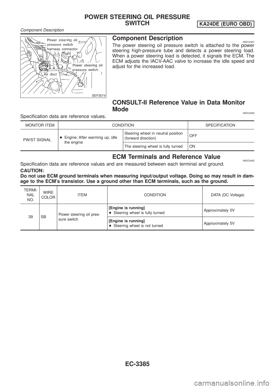
Component DescriptionNEEC0451The power steering oil pressure switch is attached to the power
steering high-pressure tube and detects a power steering load.
When a power steering load is detected, it signals the ECM. The
ECM adjusts the IACV-AAC valve to increase the idle speed and
adjust for the increased load.
CONSULT-II Reference Value in Data Monitor
Mode
NEEC0452Specification data are reference values.
MONITOR ITEM CONDITION SPECIFICATION
PW/ST SIGNAL+Engine: After warming up, idle
the engineSteering wheel in neutral position
(forward direction)OFF
The steering wheel is fully turned ON
ECM Terminals and Reference ValueNEEC0453Specification data are reference values and are measured between each terminal and ground.
CAUTION:
Do not use ECM ground terminals when measuring input/output voltage. Doing so may result in dam-
age to the ECM's transistor. Use a ground other than ECM terminals, such as the ground.
TERMI-
NAL
NO.WIRE
COLORITEM CONDITION DATA (DC Voltage)
39 SBPower steering oil pres-
sure switch[Engine is running]
+Steering wheel is fully turnedApproximately 0V
[Engine is running]
+Steering wheel is not turnedApproximately 5V
POWER STEERING OIL PRESSURE
SWITCH
KA24DE (EURO OBD)
Component Description
EC-3385
Page 423 of 1306
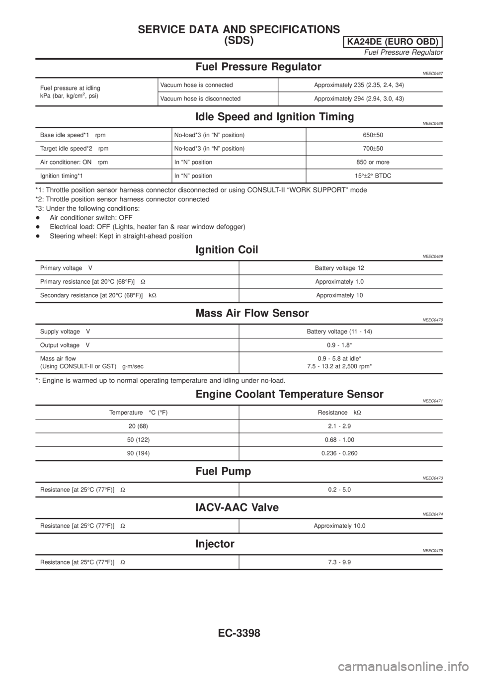
Fuel Pressure RegulatorNEEC0467
Fuel pressure at idling
kPa (bar, kg/cm2, psi)Vacuum hose is connected Approximately 235 (2.35, 2.4, 34)
Vacuum hose is disconnected Approximately 294 (2.94, 3.0, 43)
Idle Speed and Ignition TimingNEEC0468
Base idle speed*1 rpm No-load*3 (in ªNº position) 650±50
Target idle speed*2 rpm No-load*3 (in ªNº position) 700±50
Air conditioner: ON rpm In ªNº position 850 or more
Ignition timing*1 In ªNº position 15ɱ2É BTDC
*1: Throttle position sensor harness connector disconnected or using CONSULT-II ªWORK SUPPORTº mode
*2: Throttle position sensor harness connector connected
*3: Under the following conditions:
+Air conditioner switch: OFF
+Electrical load: OFF (Lights, heater fan & rear window defogger)
+Steering wheel: Kept in straight-ahead position
Ignition CoilNEEC0469
Primary voltage VBattery voltage 12
Primary resistance [at 20ÉC (68ÉF)]WApproximately 1.0
Secondary resistance [at 20ÉC (68ÉF)] kWApproximately 10
Mass Air Flow SensorNEEC0470
Supply voltage VBattery voltage (11 - 14)
Output voltage V0.9 - 1.8*
Mass air flow
(Using CONSULT-II or GST) g´m/sec0.9 - 5.8 at idle*
7.5 - 13.2 at 2,500 rpm*
*: Engine is warmed up to normal operating temperature and idling under no-load.
Engine Coolant Temperature SensorNEEC0471
Temperature ÉC (ÉF) Resistance kW
20 (68) 2.1 - 2.9
50 (122) 0.68 - 1.00
90 (194) 0.236 - 0.260
Fuel PumpNEEC0473
Resistance [at 25ÉC (77ÉF)]W0.2 - 5.0
IACV-AAC ValveNEEC0474
Resistance [at 25ÉC (77ÉF)]WApproximately 10.0
InjectorNEEC0475
Resistance [at 25ÉC (77ÉF)]W7.3 - 9.9
SERVICE DATA AND SPECIFICATIONS
(SDS)
KA24DE (EURO OBD)
Fuel Pressure Regulator
EC-3398