2001 NISSAN PICK-UP ESP
[x] Cancel search: ESPPage 2 of 1306
FOREWORD
This manual contains maintenance and repair procedures for NISSAN
PICKUP, model D22 series.
In order to assure your safety and the efficient functioning of the vehicle,
this manual should be read thoroughly. It is especially important that the
PRECAUTIONS in the GI section be completely understood before starting
any repair task.
All information in this manual is based on the latest product information
at the time of publication. The right is reserved to make changes in speci-
®cations and methods at any time without notice.
IMPORTANT SAFETY NOTICE
The proper performance of service is essential for both the safety of the
technician and the efficient functioning of the vehicle.
The service methods in this Service Manual are described in such a man-
ner that the service may be performed safely and accurately.
Service varies with the procedures used, the skills of the technician and the
tools and parts available. Accordingly, anyone using service procedures,
tools or parts which are not speci®cally recommended by NISSAN must
®rst completely satisfy himself that neither his safety nor the vehicle's
safety will be jeopardized by the service method selected.
NISSAN EUROPE S.A.S.
Service Engineering Section
Paris, France
Page 37 of 1306
Supplemental Restraint System (SRS) ªAIR
BAGº and ªSEAT BELT PRE-TENSIONERº
NEEC0002The Supplemental Restraint System such as ªAIR BAGº and ªSEAT BELT PRE-TENSIONERº used along with
a seat belt, helps to reduce the risk or severity of injury to the driver and front passenger in a frontal collision.
The SRS system composition which is available to NISSAN MODEL D22 is as follows (The composition var-
ies according to the destination and optional equipment.):
Driver air bag module (located in the center of the steering wheel), front passenger air bag module (located
on the instrument panel on passenger side), seat belt pre-tensioner, a diagnosis sensor unit, warning lamp,
wiring harness and spiral cable.
Information necessary to service the system safely is included in theRS sectionof this Service Manual.
WARNING:
+To avoid rendering the SRS inoperative, which could increase the risk of personal injury or death
in the event of a collision which would result in air bag inflation, all maintenance must be performed
by an authorized NISSAN dealer.
+Improper maintenance, including incorrect removal and installation of the SRS, can lead to per-
sonal injury caused by unintentional activation of the system. For removal of Spiral Cable and Air
Bag Module, see the RS section.
+Do not use electrical test equipment on any circuit related to the SRS unless instructed to in this
Service Manual. SRS wiring harnesses can be identified by yellow harness connector.
Precautions for On Board Diagnostic (OBD)
System of Engine
NEEC0003The ECM has an on board diagnostic system. It will light up the malfunction indicator (MI) to warn the driver
of a malfunction causing emission deterioration.
CAUTION:
+Be sure to turn the ignition switch OFF and disconnect the negative battery terminal before any
repair or inspection work. The open/short circuit of related switches, sensors, solenoid valves, etc.
will cause the MI to light up.
+Be sure to connect and lock the connectors securely after work. A loose (unlocked) connector will
cause the MI to light up due to the open circuit. (Be sure the connector is free from water, grease,
dirt, bent terminals, etc.)
+Certain systems and components, especially those related to OBD, may use a new style slide-
locking type harness connector.
For description and how to disconnect, refer to EL section, ªHARNESS CONNECTORº.
+Be sure to route and secure the harnesses properly after work. The interference of the harness with
a bracket, etc. may cause the MI to light up due to the short circuit.
+Be sure to connect rubber tubes properly after work. A misconnected or disconnected rubber tube
may cause the MI to light up due to the malfunction of the fuel injection system, etc.
+Be sure to erase the unnecessary malfunction information (repairs completed) from the ECM before
returning the vehicle to the customer.
PRECAUTIONSKA24DE (EURO OBD)
Supplemental Restraint System (SRS) ªAIR BAGº and ªSEAT BELT PRE-TENSIONERº
EC-3012
Page 77 of 1306
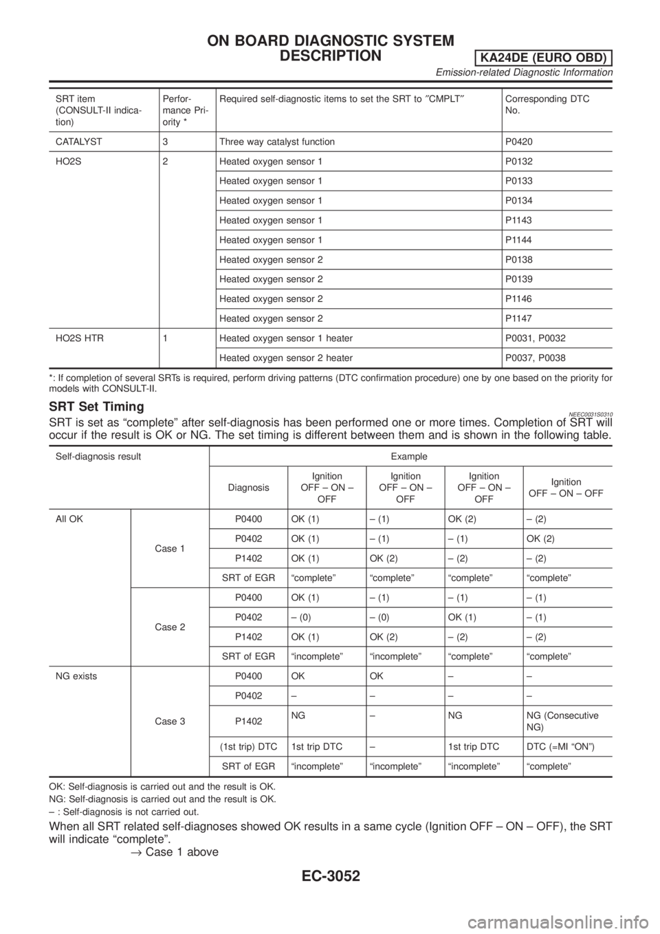
SRT item
(CONSULT-II indica-
tion)Perfor-
mance Pri-
ority *Required self-diagnostic items to set the SRT to²CMPLT²Corresponding DTC
No.
CATALYST 3 Three way catalyst function P0420
HO2S 2 Heated oxygen sensor 1 P0132
Heated oxygen sensor 1 P0133
Heated oxygen sensor 1 P0134
Heated oxygen sensor 1 P1143
Heated oxygen sensor 1 P1144
Heated oxygen sensor 2 P0138
Heated oxygen sensor 2 P0139
Heated oxygen sensor 2 P1146
Heated oxygen sensor 2 P1147
HO2S HTR 1 Heated oxygen sensor 1 heater P0031, P0032
Heated oxygen sensor 2 heater P0037, P0038
*: If completion of several SRTs is required, perform driving patterns (DTC confirmation procedure) one by one based on the priority for
models with CONSULT-II.
SRT Set TimingNEEC0031S0310SRT is set as ªcompleteº after self-diagnosis has been performed one or more times. Completion of SRT will
occur if the result is OK or NG. The set timing is different between them and is shown in the following table.
Self-diagnosis result Example
DiagnosisIgnition
OFF±ON±
OFFIgnition
OFF±ON±
OFFIgnition
OFF±ON±
OFFIgnition
OFF±ON±OFF
All OK
Case 1P0400 OK (1) ± (1) OK (2) ± (2)
P0402 OK (1) ± (1) ± (1) OK (2)
P1402 OK (1) OK (2) ± (2) ± (2)
SRT of EGR ªcompleteº ªcompleteº ªcompleteº ªcompleteº
Case 2P0400 OK (1) ± (1) ± (1) ± (1)
P0402 ± (0) ± (0) OK (1) ± (1)
P1402 OK (1) OK (2) ± (2) ± (2)
SRT of EGR ªincompleteº ªincompleteº ªcompleteº ªcompleteº
NG exists
Case 3P0400 OK OK ± ±
P0402±±±±
P1402NG ± NG NG (Consecutive
NG)
(1st trip) DTC 1st trip DTC ± 1st trip DTC DTC (=MI ªONº)
SRT of EGR ªincompleteº ªincompleteº ªincompleteº ªcompleteº
OK: Self-diagnosis is carried out and the result is OK.
NG: Self-diagnosis is carried out and the result is OK.
± : Self-diagnosis is not carried out.
When all SRT related self-diagnoses showed OK results in a same cycle (Ignition OFF ± ON ± OFF), the SRT
will indicate ªcompleteº.
®Case 1 above
ON BOARD DIAGNOSTIC SYSTEM
DESCRIPTION
KA24DE (EURO OBD)
Emission-related Diagnostic Information
EC-3052
Page 78 of 1306
When all SRT related self-diagnoses show OK results through several different cycles, the SRT will indicate
ªcompleteº at the time the respective self-diagnoses have at least one OK result.
®Case 2 above
If one or more SRT related self-diagnoses showed NG results in 2 consecutive cycles, the SRT will also indi-
cate ªcompleteº.
®Case 3 above
The previous table shows that the minimum number of cycles for setting SRT as ªincompleteº is one (1) for
each self-diagnosis (Case 1 and 2) or two (2) for one self-diagnosis (Case 3). However, in preparation for the
State emissions inspection, it is unnecessary of each self-diagnosis to be executed twice (Case 3) because
of the following reasons;
+The SRT will indicate ªcompleteº at the time the respective self-diagnoses have one (1) OK result.
+The emissions inspection requires ªcompleteº of the SRT only with OK self-diagnosis result.
+When, during SRT driving pattern, 1st trip DTC (NG) is detected prior to ªcompleteº of SRT, the self-diag-
nosis memory must be erased from ECM after repair.
+If the 1st trip DTC is erased, all the SRT will indicate ªincompleteº.
NOTE:
SRT can be set as ªcompleteº together with the DTC(s). Therefore, DTC check must always be carried out
prior to the State emission inspection even though the SRT indicates ªcompleteº.
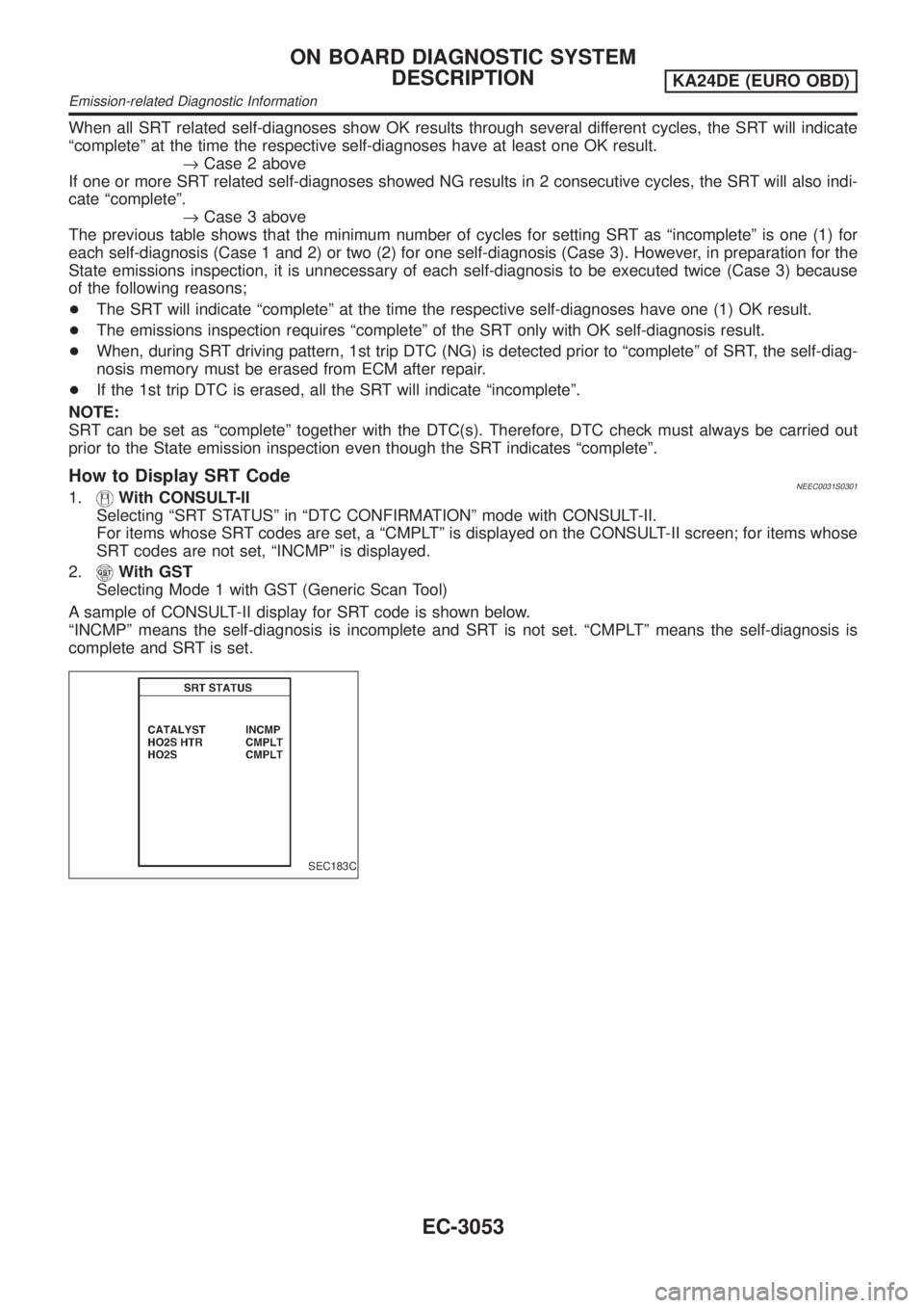
How to Display SRT CodeNEEC0031S03011.With CONSULT-II
Selecting ªSRT STATUSº in ªDTC CONFIRMATIONº mode with CONSULT-II.
For items whose SRT codes are set, a ªCMPLTº is displayed on the CONSULT-II screen; for items whose
SRT codes are not set, ªINCMPº is displayed.
2.
With GST
Selecting Mode 1 with GST (Generic Scan Tool)
A sample of CONSULT-II display for SRT code is shown below.
ªINCMPº means the self-diagnosis is incomplete and SRT is not set. ªCMPLTº means the self-diagnosis is
complete and SRT is set.
SEC183C
ON BOARD DIAGNOSTIC SYSTEM
DESCRIPTION
KA24DE (EURO OBD)
Emission-related Diagnostic Information
EC-3053
Page 80 of 1306
How to Set SRT Code=NEEC0031S0302To set all SRT codes, self-diagnosis for the items indicated above must be performed one or more times. Each
diagnosis may require a long period of actual driving under various conditions.
With CONSULT-II
Perform corresponding DTC confirmation procedure one by one based on ªPerformance Priorityº in the table
on EC-3051.
Without CONSULT-II
The most efficient driving pattern in which SRT codes can be properly set is explained on EC-3056. The driv-
ing pattern should be performed one or more times to set all SRT codes.
ON BOARD DIAGNOSTIC SYSTEM
DESCRIPTION
KA24DE (EURO OBD)
Emission-related Diagnostic Information
EC-3055
Page 103 of 1306
DTC & SRT CONFIRMATION MODE=NEEC0034S08SRT STATUS ModeNEEC0034S0801For details, refer to ªSYSTEM READINESS TEST (SRT) CODEº,
EC-3051.
SRT Work Support ModeNEEC0034S0803This mode enables a technician to drive a vehicle to set the SRT
while monitoring the SRT status.
DTC Work Support ModeNEEC0034S0802
TEST MODE TEST ITEM CONDITION REFERENCE PAGE
HO2S1HO2S1 (B1) P0133
Refer to corresponding
trouble diagnosis for
DTC.EC-3202
HO2S1 (B1) P0134 EC-3213
HO2S1 (B1) P1143 EC-3310
HO2S1 (B1) P1144 EC-3317
HO2S2HO2S2 (B1) P0139 EC-3227
HO2S2 (B1) P1146 EC-3324
HO2S2 (B1) P1147 EC-3334
REAL TIME DIAGNOSIS IN DATA MONITOR MODE
(RECORDING VEHICLE DATA)
NEEC0034S10CONSULT-II has two kinds of triggers and they can be selected by
touching ªSETTINGº in ªDATA MONITORº mode.
1) ªAUTO TRIGº (Automatic trigger):
+The malfunction will be identified on the CONSULT-II screen in
real time.
In other words, DTC/1st trip DTC and malfunction item will be
displayed if the malfunction is detected by ECM.
At the moment a malfunction is detected by ECM, ªMONITORº
in ªDATA MONITORº screen is changed to ªRecording Data ...
xx%º as shown at left, and the data after the malfunction detec-
tion is recorded. Then the percentage reached 100%, ªREAL-
TIME DIAGº screen is displayed. If ªSTOPº is touched on the
screen during ªRecording Data ... xx%º, ªREAL-TIME DIAGº
screen is also displayed.
The recording time after the malfunction detection and the
recording speed can be changed by ªTRIGGER POINTº and
ªRECORDING Speedº. Refer to CONSULT-II OPERATION
MANUAL.
2) ªMANU TRIGº (Manual trigger):
+DTC/1st trip DTC and malfunction item will not be displayed
automatically on CONSULT-II screen even though a malfunc-
tion is detected by ECM.
DATA MONITOR can be performed continuously even though
a malfunction is detected.
Use these triggers as follows:
1) ªAUTO TRIGº
+While trying to detect the DTC/1st trip DTC by performing the
ªDIAGNOSTIC TROUBLE CODE CONFIRMATION
PROCEDUREº, be sure to select to ªDATA MONITOR (AUTO
TRIG)º mode. You can confirm the malfunction at the moment
it is detected.
+While narrowing down the possible causes, CONSULT-II
should be set in ªDATA MONITOR (AUTO TRIG)º mode, espe-
cially in case the incident is intermittent.
ON BOARD DIAGNOSTIC SYSTEM
DESCRIPTION
KA24DE (EURO OBD)
CONSULT-II
EC-3078
Page 107 of 1306
MEF036D
IntroductionNEEC0036
SEF233G
SEF234G
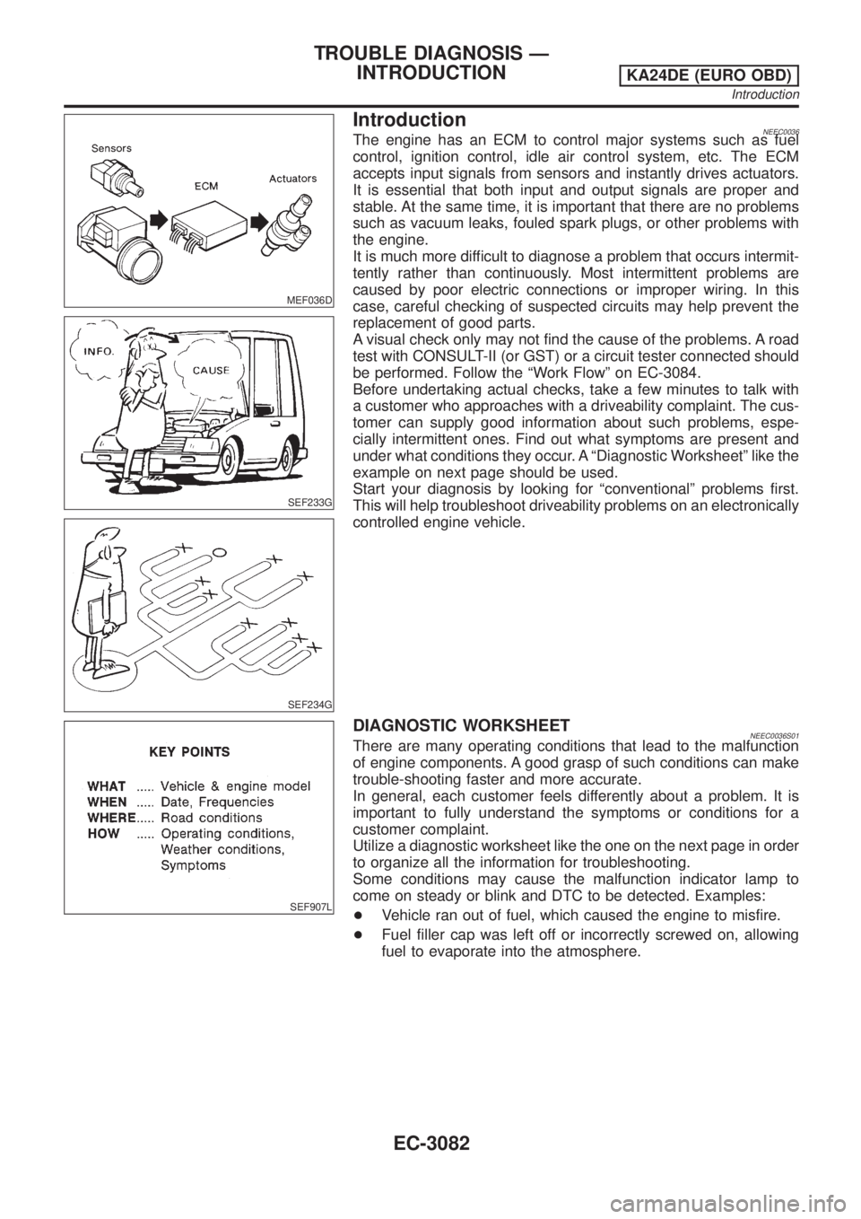
The engine has an ECM to control major systems such as fuel
control, ignition control, idle air control system, etc. The ECM
accepts input signals from sensors and instantly drives actuators.
It is essential that both input and output signals are proper and
stable. At the same time, it is important that there are no problems
such as vacuum leaks, fouled spark plugs, or other problems with
the engine.
It is much more difficult to diagnose a problem that occurs intermit-
tently rather than continuously. Most intermittent problems are
caused by poor electric connections or improper wiring. In this
case, careful checking of suspected circuits may help prevent the
replacement of good parts.
A visual check only may not find the cause of the problems. A road
test with CONSULT-II (or GST) or a circuit tester connected should
be performed. Follow the ªWork Flowº on EC-3084.
Before undertaking actual checks, take a few minutes to talk with
a customer who approaches with a driveability complaint. The cus-
tomer can supply good information about such problems, espe-
cially intermittent ones. Find out what symptoms are present and
under what conditions they occur. A ªDiagnostic Worksheetº like the
example on next page should be used.
Start your diagnosis by looking for ªconventionalº problems first.
This will help troubleshoot driveability problems on an electronically
controlled engine vehicle.
SEF907L
DIAGNOSTIC WORKSHEETNEEC0036S01There are many operating conditions that lead to the malfunction
of engine components. A good grasp of such conditions can make
trouble-shooting faster and more accurate.
In general, each customer feels differently about a problem. It is
important to fully understand the symptoms or conditions for a
customer complaint.
Utilize a diagnostic worksheet like the one on the next page in order
to organize all the information for troubleshooting.
Some conditions may cause the malfunction indicator lamp to
come on steady or blink and DTC to be detected. Examples:
+Vehicle ran out of fuel, which caused the engine to misfire.
+Fuel filler cap was left off or incorrectly screwed on, allowing
fuel to evaporate into the atmosphere.
TROUBLE DIAGNOSIS Ð
INTRODUCTION
KA24DE (EURO OBD)
Introduction
EC-3082
Page 158 of 1306
DescriptionNEEC0136SYSTEM DESCRIPTIONNEEC0136S01
Sensor Input Signal to ECMECM func-
tionActuator
Camshaft position sensor Engine speedHeated
oxygen
sensor 1
heater con-
trolHeated oxygen sensor 1 heater
The ECM performs ON/OFF control of the heated oxygen sensor 1 heater corresponding to the engine oper-
ating condition.
OPERATIONNEEC0136S02
Engine speed Heated oxygen sensor 1 heater
Above 3,600 rpm OFF
Below 3,600 rpm ON
CONSULT-II Reference Value in Data Monitor
Mode
NEEC0137Specification data are reference values.
MONITOR ITEM CONDITION SPECIFICATION
HO2S1 HTR (B1)+Engine speed: Below 3,600 rpm ON
+Engine speed: Above 3,600 rpm OFF
ECM Terminals and Reference ValueNEEC0138Specification data are reference values and are measured between each terminal and ground.
CAUTION:
Do not use ECM ground terminals when measuring input/output voltage. Doing so may result in dam-
age to the ECM's transistor. Use a ground other than ECM terminals, such as the ground.
TERMI-
NAL
NO.WIRE
COLORITEM CONDITION DATA (DC Voltage)
119 Y/RHeated oxygen sensor 1
heater[Engine is running]
+Engine speed is below 3,600 rpm.Approximately 0.4V
[Engine is running]
+Engine speed is above 3,600 rpm.BATTERY VOLTAGE
(11 - 14V)
On Board Diagnosis LogicNEEC0139
DTC No.Trouble diag-
nosis nameDTC detecting condition Possible cause
P0031
0031Heated oxy-
gen sensor 1
heater con-
trol circuit
low+The current amperage in the heated oxygen sen-
sor 1 heater circuit is out of the normal range.
(An excessively low voltage signal is sent to
ECM through the heated oxygen sensor 1
heater.)+Harness or connectors
(The heated oxygen sensor 1 heater circuit
is open or shorted.)
+Heated oxygen sensor 1 heater
P0032
0032Heated oxy-
gen sensor 1
heater con-
trol circuit
high+The current amperage in the heated oxygen sen-
sor 1 heater circuit is out of the normal range.
(An excessively high voltage signal is sent to
ECM through the heated oxygen sensor 1
heater.)+Harness or connectors
(The heated oxygen sensor 1 heater circuit
is shorted.)
+Heated oxygen sensor 1 heater
DTC P0031, P0032 HO2S1 HEATERKA24DE (EURO OBD)
Description
EC-3133