2001 NISSAN PICK-UP ESP
[x] Cancel search: ESPPage 163 of 1306
DescriptionNEEC0180SYSTEM DESCRIPTIONNEEC0180S01
Sensor Input Signal to ECMECM func-
tionActuator
Camshaft position sensor Engine speedHeated
oxygen
sensor 2
heater con-
trolHeated oxygen sensor 2 heater
The ECM performs ON/OFF control of the heated oxygen sensor 2 heater corresponding to the engine speed.
OPERATIONNEEC0180S02
Engine speed rpm Heated oxygen sensor 2 heater
Above 4,000 OFF
Below 4,000 ON
CONSULT-II Reference Value in Data Monitor
Mode
NEEC0181Specification data are reference values.
MONITOR ITEM CONDITION SPECIFICATION
HO2S2 HTR (B1)+Engine speed: Below 4,000 rpm [After driving for 2 minutes at a
speed of 70 km/h (43 MPH) or more]ON
+Ignition switch ON (Engine stopped)
+Engine is running above 4,000 rpmOFF
ECM Terminals and Reference ValueNEEC0182Specification data are reference values and are measured between each terminal and ground.
CAUTION:
Do not use ECM ground terminals when measuring input/output voltage. Doing so may result in dam-
age to the ECM's transistor. Use a ground other than ECM terminals, such as the ground.
TERMI-
NAL
NO.WIRE
COLORITEM CONDITION DATA (DC Voltage)
122 G/BHeated oxygen sensor 2
heater[Engine is running]
+After driving for 2 minutes at a speed of 70 km/h
(43 MPH) or moreApproximately 0.4V
[Ignition switch ªONº]
+Engine stoppedBATTERY VOLTAGE
(11 - 14V)
On Board Diagnosis LogicNEEC0183
DTC No.Trouble diag-
nosis nameDTC detecting condition Possible cause
P0037
0037Heated oxy-
gen sensor 2
heater con-
trol circuit
low+The current amperage in the heated oxygen sen-
sor 2 heater circuit is out of the normal range.
(An excessively low voltage signal is sent to
ECM through the heated oxygen sensor 2
heater.)+Harness or connectors
(The heated oxygen sensor 2 heater circuit
is open or shorted.)
+Heated oxygen sensor 2 heater
DTC P0037, P0038 HO2S2 HEATERKA24DE (EURO OBD)
Description
EC-3138
Page 170 of 1306
SEF243Y
SEF175Y
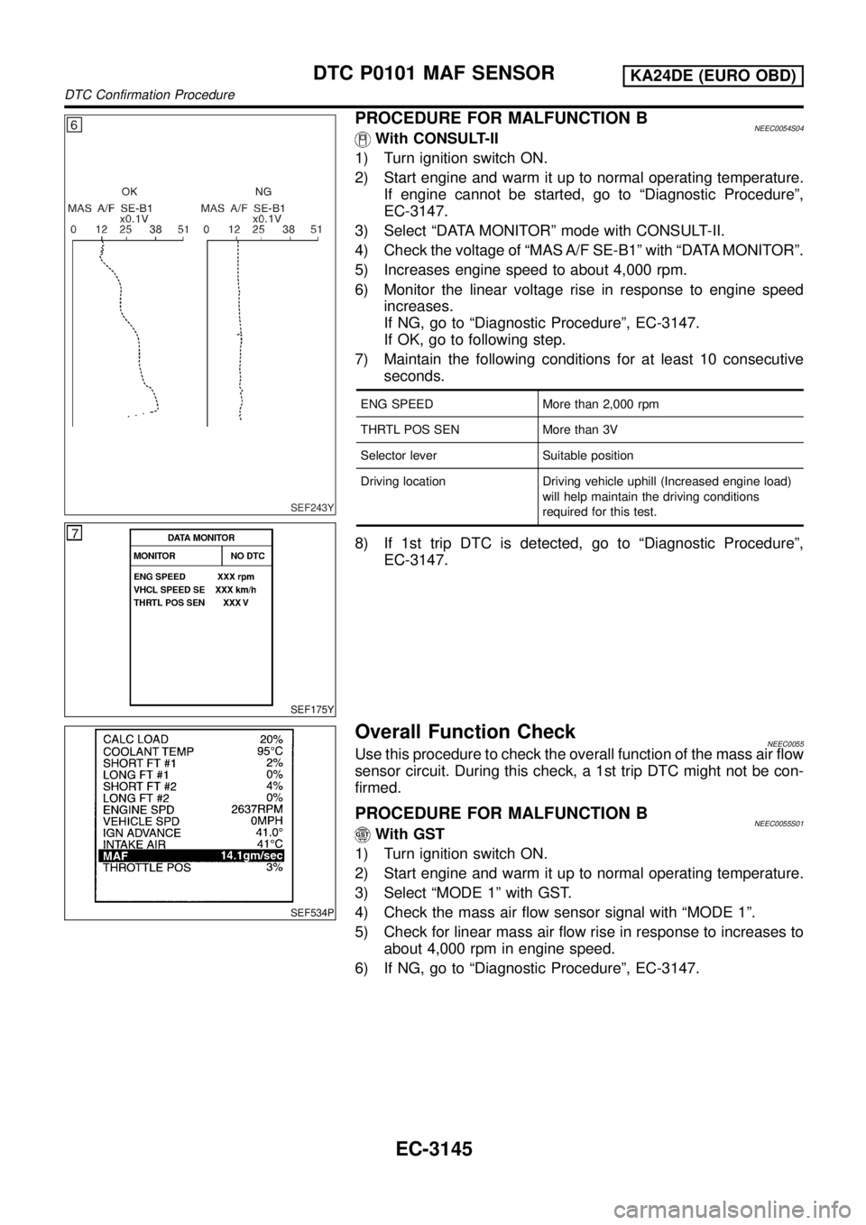
PROCEDURE FOR MALFUNCTION BNEEC0054S04With CONSULT-II
1) Turn ignition switch ON.
2) Start engine and warm it up to normal operating temperature.
If engine cannot be started, go to ªDiagnostic Procedureº,
EC-3147.
3) Select ªDATA MONITORº mode with CONSULT-II.
4) Check the voltage of ªMAS A/F SE-B1º with ªDATA MONITORº.
5) Increases engine speed to about 4,000 rpm.
6) Monitor the linear voltage rise in response to engine speed
increases.
If NG, go to ªDiagnostic Procedureº, EC-3147.
If OK, go to following step.
7) Maintain the following conditions for at least 10 consecutive
seconds.
ENG SPEED More than 2,000 rpm
THRTL POS SEN More than 3V
Selector lever Suitable position
Driving location Driving vehicle uphill (Increased engine load)
will help maintain the driving conditions
required for this test.
8) If 1st trip DTC is detected, go to ªDiagnostic Procedureº,
EC-3147.
SEF534P
Overall Function CheckNEEC0055Use this procedure to check the overall function of the mass air flow
sensor circuit. During this check, a 1st trip DTC might not be con-
firmed.
PROCEDURE FOR MALFUNCTION BNEEC0055S01With GST
1) Turn ignition switch ON.
2) Start engine and warm it up to normal operating temperature.
3) Select ªMODE 1º with GST.
4) Check the mass air flow sensor signal with ªMODE 1º.
5) Check for linear mass air flow rise in response to increases to
about 4,000 rpm in engine speed.
6) If NG, go to ªDiagnostic Procedureº, EC-3147.
DTC P0101 MAF SENSORKA24DE (EURO OBD)
DTC Confirmation Procedure
EC-3145
Page 185 of 1306
SEF329V
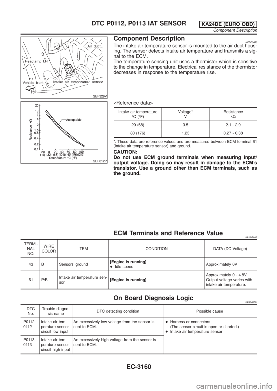
Component DescriptionNEEC0066The intake air temperature sensor is mounted to the air duct hous-
ing. The sensor detects intake air temperature and transmits a sig-
nal to the ECM.
The temperature sensing unit uses a thermistor which is sensitive
to the change in temperature. Electrical resistance of the thermistor
decreases in response to the temperature rise.
SEF012P
Intake air temperature
ÉC (ÉF)Voltage*
VResistance
kW
20 (68) 3.5 2.1 - 2.9
80 (176) 1.23 0.27 - 0.38
*: These data are reference values and are measured between ECM terminal 61
(Intake air temperature sensor) and ground.
CAUTION:
Do not use ECM ground terminals when measuring input/
output voltage. Doing so may result in damage to the ECM's
transistor. Use a ground other than ECM terminals, such as
the ground.
ECM Terminals and Reference ValueNEEC1556
TERMI-
NAL
NO.WIRE
COLORITEM CONDITION DATA (DC Voltage)
43 B Sensors' ground[Engine is running]
+Idle speedApproximately 0V
61 P/BIntake air temperature sen-
sor[Engine is running]Approximately 0 - 4.8V
Output voltage varies with
intake air temperature.
On Board Diagnosis LogicNEEC0067
DTC
No.Trouble diagno-
sis nameDTC detecting condition Possible cause
P0112
0112Intake air tem-
perature sensor
circuit low inputAn excessively low voltage from the sensor is
sent to ECM.+Harness or connectors
(The sensor circuit is open or shorted.)
+Intake air temperature sensor
P0113
0113Intake air tem-
perature sensor
circuit high inputAn excessively high voltage from the sensor is
sent to ECM.
DTC P0112, P0113 IAT SENSORKA24DE (EURO OBD)
Component Description
EC-3160
Page 195 of 1306
Component DescriptionNEEC0079NOTE:
If DTC P0121, P0122 or P0123 is displayed with DTC P0510, first perform trouble diagnosis for DTC
P0510, EC-3301.
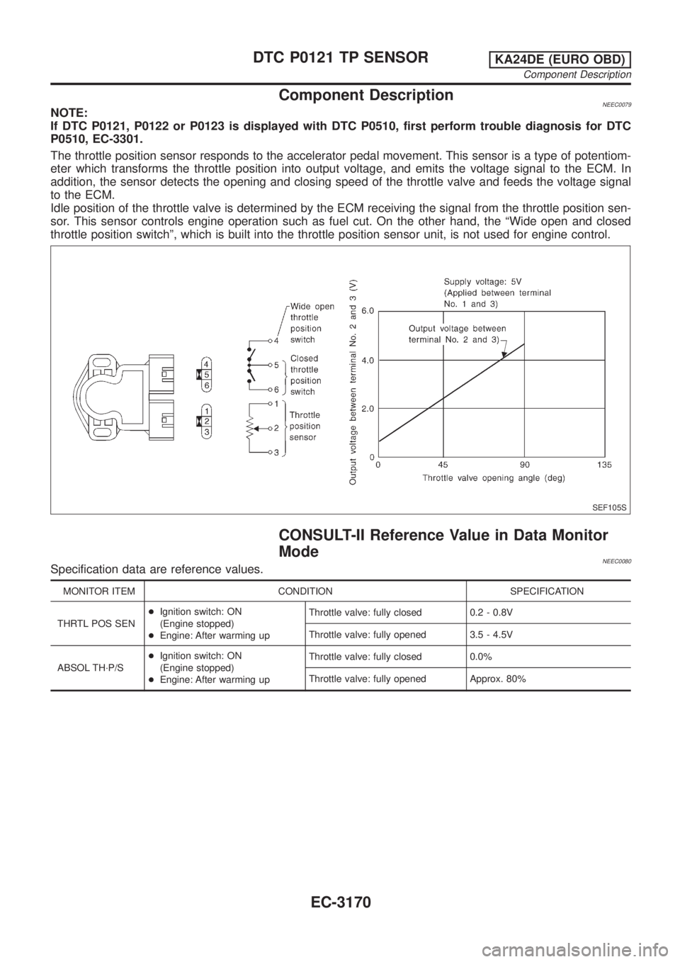
The throttle position sensor responds to the accelerator pedal movement. This sensor is a type of potentiom-
eter which transforms the throttle position into output voltage, and emits the voltage signal to the ECM. In
addition, the sensor detects the opening and closing speed of the throttle valve and feeds the voltage signal
to the ECM.
Idle position of the throttle valve is determined by the ECM receiving the signal from the throttle position sen-
sor. This sensor controls engine operation such as fuel cut. On the other hand, the ªWide open and closed
throttle position switchº, which is built into the throttle position sensor unit, is not used for engine control.
SEF105S
CONSULT-II Reference Value in Data Monitor
Mode
NEEC0080Specification data are reference values.
MONITOR ITEM CONDITION SPECIFICATION
THRTL POS SEN+Ignition switch: ON
(Engine stopped)
+Engine: After warming upThrottle valve: fully closed 0.2 - 0.8V
Throttle valve: fully opened 3.5 - 4.5V
ABSOL TH´P/S+Ignition switch: ON
(Engine stopped)
+Engine: After warming upThrottle valve: fully closed 0.0%
Throttle valve: fully opened Approx. 80%
DTC P0121 TP SENSORKA24DE (EURO OBD)
Component Description
EC-3170
Page 197 of 1306
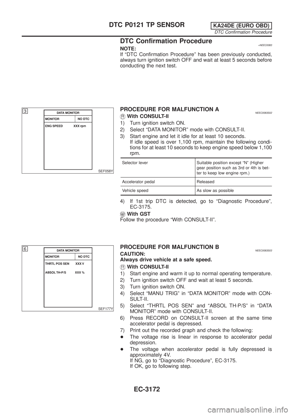
DTC Confirmation Procedure=NEEC0083NOTE:
If ªDTC Confirmation Procedureº has been previously conducted,
always turn ignition switch OFF and wait at least 5 seconds before
conducting the next test.
SEF058Y
PROCEDURE FOR MALFUNCTION ANEEC0083S02With CONSULT-II
1) Turn ignition switch ON.
2) Select ªDATA MONITORº mode with CONSULT-II.
3) Start engine and let it idle for at least 10 seconds.
If idle speed is over 1,100 rpm, maintain the following condi-
tions for at least 10 seconds to keep engine speed below 1,100
rpm.
Selector lever Suitable position except ªNº (Higher
gear position such as 3rd or 4th is bet-
ter to keep low engine rpm.)
Accelerator pedal Released
Vehicle speed As slow as possible
4) If 1st trip DTC is detected, go to ªDiagnostic Procedureº,
EC-3175.
With GST
Follow the procedure ªWith CONSULT-IIº.
SEF177Y
PROCEDURE FOR MALFUNCTION BNEEC0083S03CAUTION:
Always drive vehicle at a safe speed.
With CONSULT-II
1) Start engine and warm it up to normal operating temperature.
2) Turn ignition switch OFF and wait at least 5 seconds.
3) Turn ignition switch ON.
4) Select ªMANU TRIGº in ªDATA MONITORº mode with CON-
SULT-II.
5) Select ªTHRTL POS SENº and ªABSOL TH´P/Sº in ªDATA
MONITORº mode with CONSULT-II.
6) Press RECORD on CONSULT-II screen at the same time
accelerator pedal is depressed.
7) Print out the recorded graph and check the following:
+The voltage rise is linear in response to accelerator pedal
depression.
+The voltage when accelerator pedal is fully depressed is
approximately 4V.
If NG, go to ªDiagnostic Procedureº, EC-3175.
If OK, go to following step.
DTC P0121 TP SENSORKA24DE (EURO OBD)
DTC Confirmation Procedure
EC-3172
Page 207 of 1306
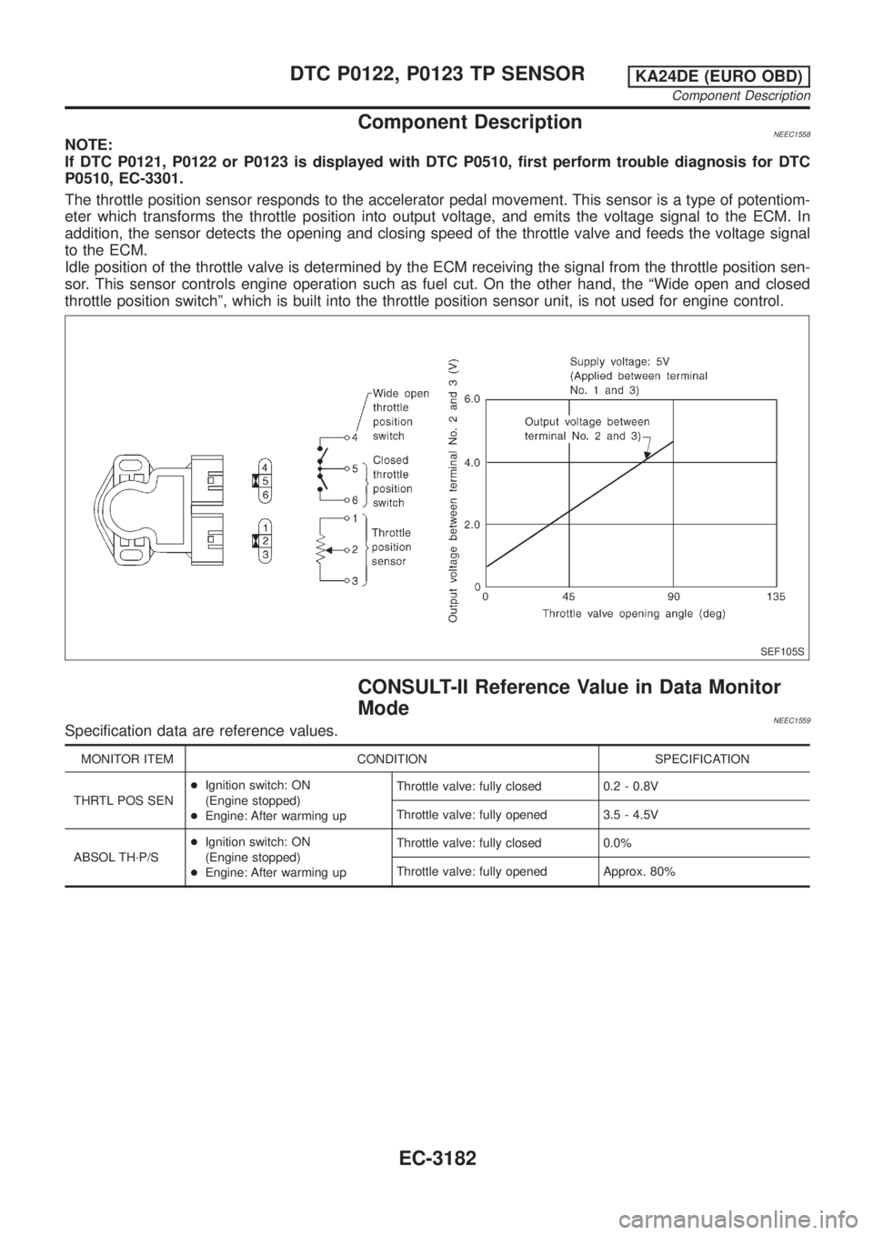
Component DescriptionNEEC1558NOTE:
If DTC P0121, P0122 or P0123 is displayed with DTC P0510, first perform trouble diagnosis for DTC
P0510, EC-3301.
The throttle position sensor responds to the accelerator pedal movement. This sensor is a type of potentiom-
eter which transforms the throttle position into output voltage, and emits the voltage signal to the ECM. In
addition, the sensor detects the opening and closing speed of the throttle valve and feeds the voltage signal
to the ECM.
Idle position of the throttle valve is determined by the ECM receiving the signal from the throttle position sen-
sor. This sensor controls engine operation such as fuel cut. On the other hand, the ªWide open and closed
throttle position switchº, which is built into the throttle position sensor unit, is not used for engine control.
SEF105S
CONSULT-II Reference Value in Data Monitor
Mode
NEEC1559Specification data are reference values.
MONITOR ITEM CONDITION SPECIFICATION
THRTL POS SEN+Ignition switch: ON
(Engine stopped)
+Engine: After warming upThrottle valve: fully closed 0.2 - 0.8V
Throttle valve: fully opened 3.5 - 4.5V
ABSOL TH´P/S+Ignition switch: ON
(Engine stopped)
+Engine: After warming upThrottle valve: fully closed 0.0%
Throttle valve: fully opened Approx. 80%
DTC P0122, P0123 TP SENSORKA24DE (EURO OBD)
Component Description
EC-3182
Page 218 of 1306

SEF329V
Component DescriptionNEEC1565The intake air temperature sensor is mounted to the air duct hous-
ing. The sensor detects intake air temperature and transmits a sig-
nal to the ECM.
The temperature sensing unit uses a thermistor which is sensitive
to the change in temperature. Electrical resistance of the thermistor
decreases in response to the temperature rise.
SEF012P
Intake air temperature
ÉC (ÉF)Voltage*
VResistance
kW
20 (68) 3.5 2.1 - 2.9
80 (176) 1.23 0.27 - 0.38
*: These data are reference values and are measured between ECM terminal 61
(Intake air temperature sensor) and ground.
CAUTION:
Do not use ECM ground terminals when measuring input/
output voltage. Doing so may result in damage to the ECM's
transistor. Use a ground other than ECM terminals, such as
the ground.
ECM Terminals and Reference ValueNEEC1570
TERMI-
NAL
NO.WIRE
COLORITEM CONDITION DATA (DC Voltage)
43 B Sensors' ground[Engine is running]
+Idle speedApproximately 0V
61 P/BIntake air temperature sen-
sor[Engine is running]Approximately 0 - 4.8V
Output voltage varies with
intake air temperature.
On Board Diagnosis LogicNEEC1566
DTC No. Malfunction is detected when ... Check Items (Possible Cause)
P0127
0127Rationally incorrect voltage from the sensor is sent to
ECM, compared with the voltage signal from engine
coolant temperature sensor.+Harness or connectors
(The sensor circuit is open or shorted.)
+Intake air temperature sensor
DTC P0127 IAT SENSORKA24DE (EURO OBD)
Component Description
EC-3193
Page 228 of 1306

SEF298U
On Board Diagnosis LogicNEEC0122To judge the malfunction of heated oxygen sensor 1, this diagno-
sis measures response time of heated oxygen sensor 1 signal. The
time is compensated by engine operating (speed and load), fuel
feedback control constant, and heated oxygen sensor 1 tempera-
ture index. Judgment is based on whether the compensated time
[heated oxygen sensor 1 cycling time index] is inordinately long or
not.
DTC No. Malfunction is detected when ... Check Items (Possible Cause)
P0133
0133+The response of the voltage signal from the sensor takes
more than the specified time.+Harness or connectors
(The sensor circuit is open or shorted.)
+Heated oxygen sensor 1
+Heated oxygen sensor 1 heater
+Fuel pressure
+Injectors
+Intake air leaks
+Exhaust gas leaks
+PCV
+Mass air flow sensor
SEF656Y
SEF657Y
SEF658Y
DTC Confirmation ProcedureNEEC0123CAUTION:
Always drive vehicle at a safe speed.
NOTE:
If ªDTC Confirmation Procedureº has been previously conducted,
always turn ignition switch OFF and wait at least 5 seconds before
conducting the next test.
TESTING CONDITION:
+Always perform at a temperature above þ10ÉC (14ÉF).
+Before performing the following procedure, confirm that
battery voltage is more than 11V at idle.
With CONSULT-II
1) Start engine and warm it up to normal operating temperature.
2) Stop engine and wait at least 5 seconds.
3) Turn ignition switch ON and select ªHO2S1 (B1) P0133º of
ªHO2S1º in ªDTC WORK SUPPORTº mode with CONSULT-II.
4) Touch ªSTARTº.
5) Start engine and let it idle for at least 3.0 minutes.
NOTE:
Never raise engine speed above 3,600 rpm after this step. If
the engine speed limit is exceeded, return to step 5.
6) When the following conditions are met, ªTESTINGº will be dis-
played on the CONSULT-II screen. Maintain the conditions
continuously until ªTESTINGº changes to ªCOMPLETEDº. (It
will take approximately 20 seconds.)
ENG SPEED 1,750 - 3,750 rpm
Vehicle speed More than 80 km/h (More than 50 MPH)
B/FUEL SCHDL 3.5 - 15.5 msec
Selector lever Suitable position
If ªTESTINGº is not displayed after 5 minutes, retry from
step 2.
DTC P0133 HO2S1KA24DE (EURO OBD)
On Board Diagnosis Logic
EC-3203