2001 NISSAN PICK-UP dimensions
[x] Cancel search: dimensionsPage 884 of 1306
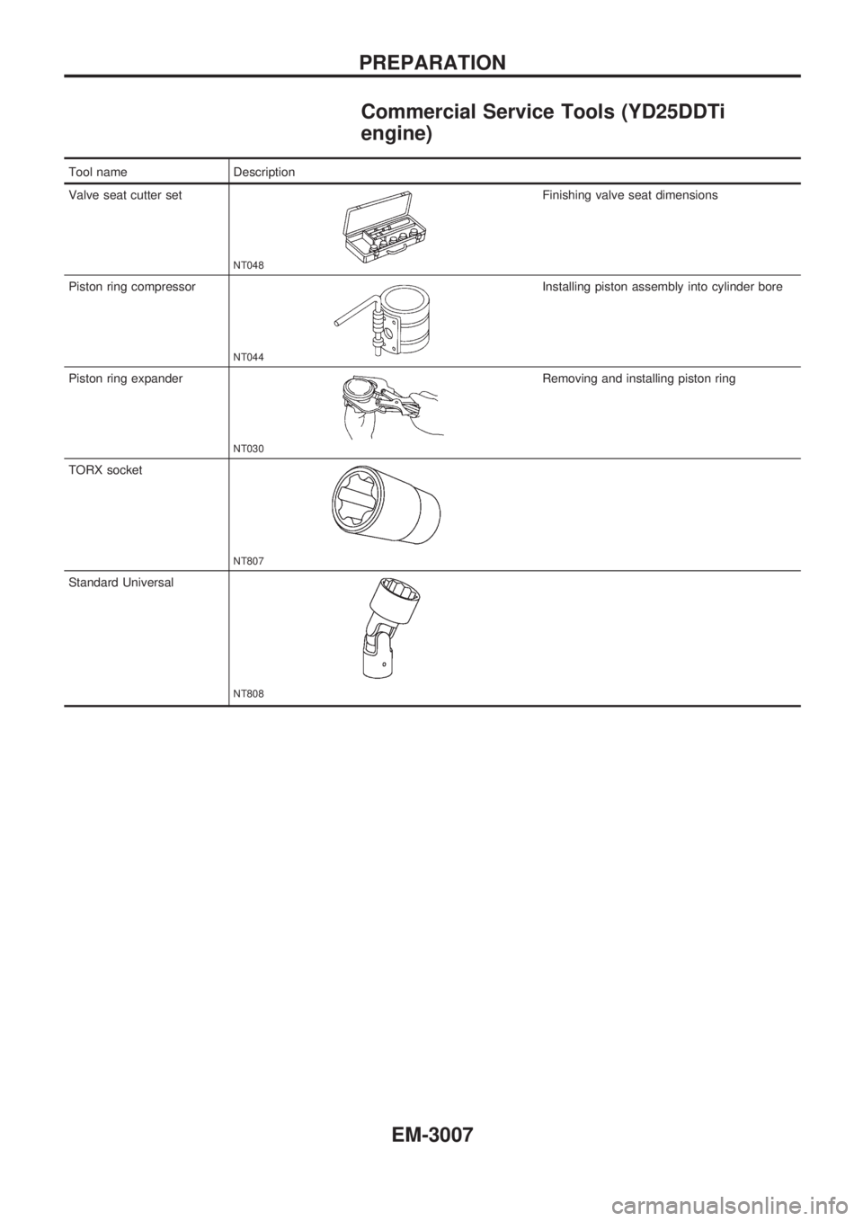
Commercial Service Tools (YD25DDTi
engine)
Tool name Description
Valve seat cutter set
NT048
Finishing valve seat dimensions
Piston ring compressor
NT044
Installing piston assembly into cylinder bore
Piston ring expander
NT030
Removing and installing piston ring
TORX socket
NT807
Standard Universal
NT808
PREPARATION
EM-3007
Page 896 of 1306
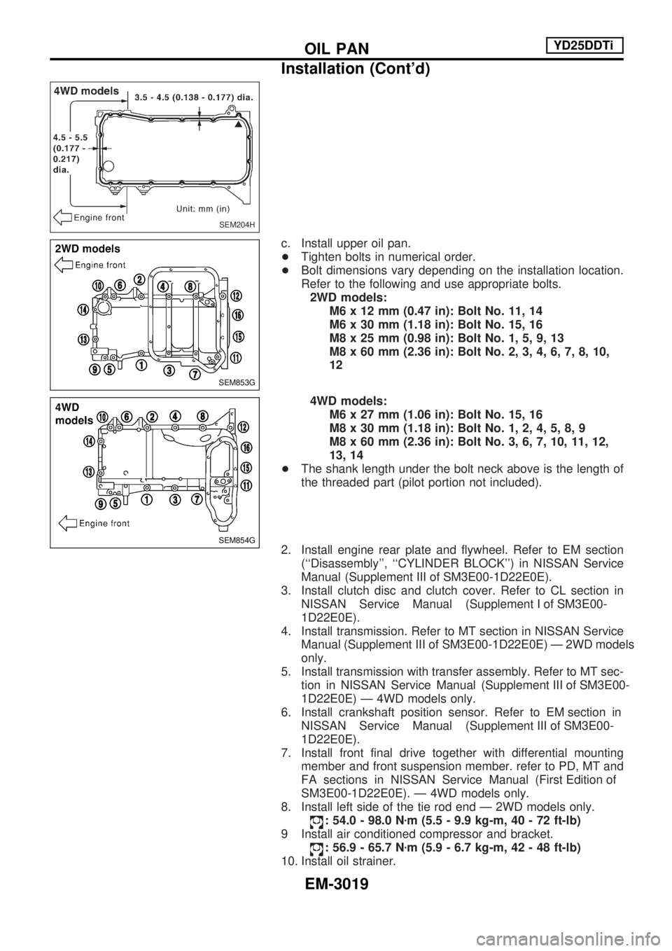
c. Install upper oil pan.
+Tighten bolts in numerical order.
+ Bolt dimensions vary depending on the installation location.
Refer to the following and use appropriate bolts.
2WD models: M6 x 12 mm (0.47 in): Bolt No. 11, 14
M6 x 30 mm (1.18 in): Bolt No. 15, 16
M8 x 25 mm (0.98 in): Bolt No. 1, 5, 9, 13
M8 x 60 mm (2.36 in): Bolt No. 2, 3, 4, 6, 7, 8, 10,
12
4WD models: M6 x 27 mm (1.06 in): Bolt No. 15, 16
M8 x 30 mm (1.18 in): Bolt No. 1, 2, 4, 5, 8, 9
M8 x 60 mm (2.36 in): Bolt No. 3, 6, 7, 10, 11, 12,
13, 14
+ The shank length under the bolt neck above is the length of
the threaded part (pilot portion not included).
2. Install engine rear plate and flywheel. Refer to EM section (``Disassembly'', ``CYLINDER BLOCK'') in NISSAN Service
Manual(Supplement III of SM3E00-1D22E0E).
3. Install clutch disc and clutch cover. Refer to CL section in NISSANServiceManual(Supplement I of SM3E00-
1D22E0E).
4. Install transmission. Refer to MT section in NISSAN Service Manual(Supplement III of SM3E00-1D22E0E)Ð2WDmodels
only.
5. Install transmission with transfer assembly. Refer to MT sec- tioninNISSANServiceManual(Supplement III of SM3E00-
1D22E0E) Ð 4WD models only.
6.Installcrankshaftpositionsensor.RefertoEM sectionin NISSANServiceManual(Supplement III of SM3E00-
1D22E0E).
7. Install front final drive together with differential mounting member and front suspension member. refer to PD, MT and
FAsectionsinNISSANServiceManual(First Edition of
SM3E00-1D22E0E). Ð 4WD models only.
8. Install left side of the tie rod end Ð 2WD models only.
: 54.0 - 98.0 N zm (5.5 - 9.9 kg-m, 40 - 72 ft-lb)
9 Install air conditioned compressor and bracket.
: 56.9 - 65.7 N zm (5.9 - 6.7 kg-m, 42 - 48 ft-lb)
10. Install oil strainer.
SEM204H
SEM853G
SEM854G
OILPAN YD25DDTi
Installation (Cont'd)
EM-3019
Page 930 of 1306
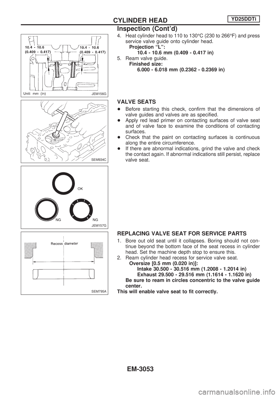
4. Heat cylinder head to 110 to 130ÉC (230 to 266ÉF) and press
service valve guide onto cylinder head.
Projection ªLº:
10.4 - 10.6 mm (0.409 - 0.417 in)
5. Ream valve guide.
Finished size:
6.000 - 6.018 mm (0.2362 - 0.2369 in)
VALVE SEATS
+Before starting this check, confirm that the dimensions of
valve guides and valves are as specified.
+Apply red lead primer on contacting surfaces of valve seat
and of valve face to examine the conditions of contacting
surfaces.
+Check that the paint on contacting surfaces is continuous
along the entire circumference.
+If there are abnormal indications, grind the valve and check
the contact again. If abnormal indications still persist, replace
valve seat.
REPLACING VALVE SEAT FOR SERVICE PARTS
1. Bore out old seat until it collapses. Boring should not con-
tinue beyond the bottom face of the seat recess in cylinder
head. Set the machine depth stop to ensure this.
2. Ream cylinder head recess for service valve seat.
Oversize [0.5 mm (0.020 in)]:
Intake 30.500 - 30.516 mm (1.2008 - 1.2014 in)
Exhaust 29.500 - 29.516 mm (1.1614 - 1.1620 in)
Be sure to ream in circles concentric to the valve guide
center.
This will enable valve seat to fit correctly.
JEM156G
SEM934C
JEM157G
SEM795A
CYLINDER HEADYD25DDTi
Inspection (Cont'd)
EM-3053
Page 931 of 1306
3. Heat cylinder head to 110 to 120ÉC (230 to 248ÉF) by soak-
ing in heated oil.
4. Sufficiently cool valve seat with dry ice. Force fit valve seat
into cylinder head.
WARNING:
Do not touch cold valve seat with your bare hands.
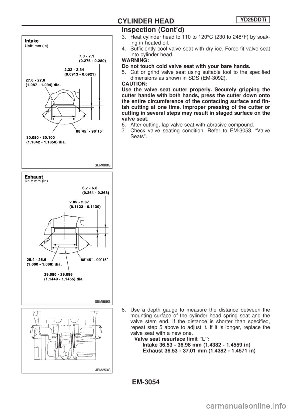
5. Cut or grind valve seat using suitable tool to the specified
dimensions as shown in SDS (EM-3092).
CAUTION:
Use the valve seat cutter properly. Securely gripping the
cutter handle with both hands, press the cutter down onto
the entire circumference of the contacting surface and fin-
ish cutting at one time. Improper pressing of the cutter or
cutting in several steps may result in staged surface on the
valve seat.
6. After cutting, lap valve seat with abrasive compound.
7. Check valve seating condition. Refer to EM-3053, ªValve
Seatsº.
8. Use a depth gauge to measure the distance between the
mounting surface of the cylinder head spring seat and the
valve stem end. If the distance is shorter than specified,
repeat step 5 above to adjust it. If it is longer, replace the
valve seat with a new one.
Valve seat resurface limit ªLº:
Intake 36.53 - 36.98 mm (1.4382 - 1.4559 in)
Exhaust 36.53 - 37.01 mm (1.4382 - 1.4571 in)
SEM888G
SEM889G
JEM253G
CYLINDER HEADYD25DDTi
Inspection (Cont'd)
EM-3054
Page 932 of 1306
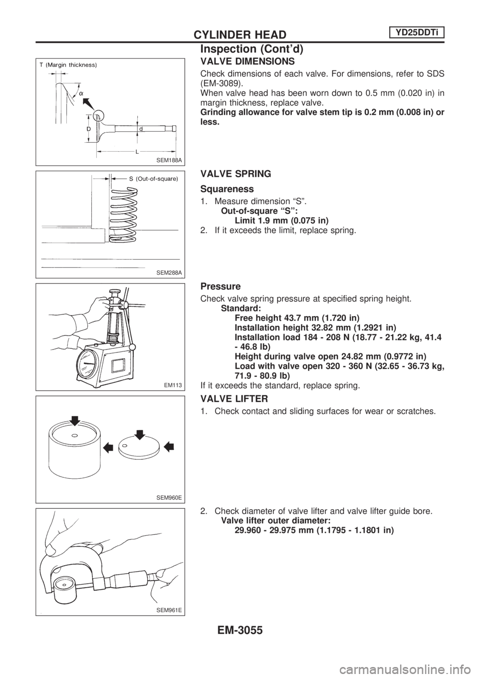
VALVE DIMENSIONS
Check dimensions of each valve. For dimensions, refer to SDS
(EM-3089).
When valve head has been worn down to 0.5 mm (0.020 in) in
margin thickness, replace valve.
Grinding allowance for valve stem tip is 0.2 mm (0.008 in) or
less.
VALVE SPRING
Squareness
1. Measure dimension ªSº.
Out-of-square ªSº:
Limit 1.9 mm (0.075 in)
2. If it exceeds the limit, replace spring.
Pressure
Check valve spring pressure at specified spring height.
Standard:
Free height 43.7 mm (1.720 in)
Installation height 32.82 mm (1.2921 in)
Installation load 184 - 208 N (18.77 - 21.22 kg, 41.4
- 46.8 lb)
Height during valve open 24.82 mm (0.9772 in)
Load with valve open 320 - 360 N (32.65 - 36.73 kg,
71.9 - 80.9 lb)
If it exceeds the standard, replace spring.
VALVE LIFTER
1. Check contact and sliding surfaces for wear or scratches.
2. Check diameter of valve lifter and valve lifter guide bore.
Valve lifter outer diameter:
29.960 - 29.975 mm (1.1795 - 1.1801 in)
SEM188A
SEM288A
EM113
SEM960E
SEM961E
CYLINDER HEADYD25DDTi
Inspection (Cont'd)
EM-3055
Page 1008 of 1306
GENERAL INFORMATION
SECTION
GI
MODIFICATION NOTICE:
+YD25DDTi engine has been adopted.
+KA24E engine has been replaced with KA24DE engine.
+The appearance design has been changed.
CONTENTS
CONSULT-II CHECKING SYSTEM..................... 3002
Function and System Application .................... 3002
Nickel Metal Hydride Battery Replacement ..... 3002
Checking Equipment ........................................ 3003
CONSULT-II Data Link Connector (DLC)
Circuit ............................................................... 3003IDENTIFICATION INFORMATION...................... 3004
Model Variation ................................................ 3004
Identification Number ....................................... 3005
Wheels and Tires ............................................. 3007
Dimensions ...................................................... 3007
This modification has been included in production starting with the following vehicle identification numbers
(Chassis number):
JN1APGD22U0050001
JN1BPGD22U0030001
JN1APUD22U0030001
JN1BPUD22U0070001
JN1CPUD22U0070001
JN1ADGD22U0020001
JN1BDGD22U0030001
JN1BDUD22U0030001
JN1CDUD22U0030001
JN1CPGD22U0040001
JN1CPGD22U0740101
JN1CDUD22U0740101
JN1CPUD22U0765101
GI
Page 1014 of 1306
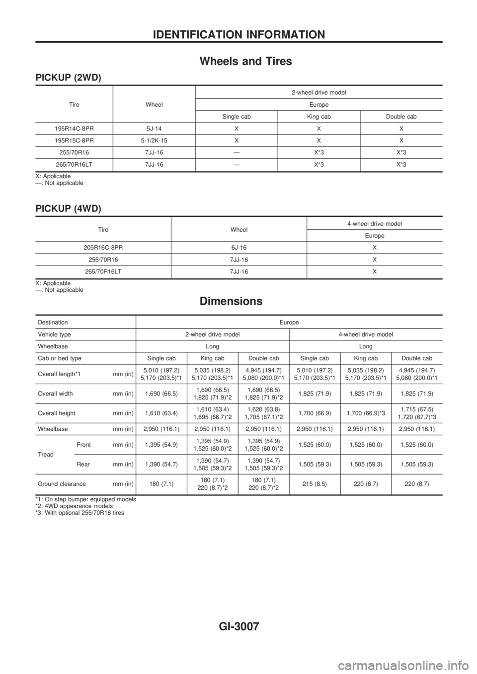
Wheels and Tires
PICKUP (2WD)
Tire Wheel2-wheel drive model
Europe
Single cab King cab Double cab
195R14C-8PR 5J-14 X X X
195R15C-8PR 5-1/2K-15 X X X
255/70R16 7JJ-16 Ð X*3 X*3
265/70R16LT 7JJ-16 Ð X*3 X*3
X: Applicable
Ð: Not applicable
PICKUP (4WD)
Tire Wheel4-wheel drive model
Europe
205R16C-8PR 6J-16 X
255/70R16 7JJ-16 X
265/70R16LT 7JJ-16 X
X: Applicable
Ð: Not applicable
Dimensions
DestinationEurope
Vehicle type 2-wheel drive model 4-wheel drive model
Wheelbase Long Long
Cab or bed type Single cab King cab Double cab Single cab King cab Double cab
Overall length*1 mm (in)5,010 (197.2)
5,170 (203.5)*15,035 (198.2)
5,170 (203.5)*14,945 (194.7)
5,080 (200.0)*15,010 (197.2)
5,170 (203.5)*15,035 (198.2)
5,170 (203.5)*14,945 (194.7)
5,080 (200.0)*1
Overall width mm (in) 1,690 (66.5)1,690 (66.5)
1,825 (71.9)*21,690 (66.5)
1,825 (71.9)*21,825 (71.9) 1,825 (71.9) 1,825 (71.9)
Overall height mm (in) 1,610 (63.4)1,610 (63.4)
1,695 (66.7)*21,620 (63.8)
1,705 (67.1)*21,700 (66.9) 1,700 (66.9)*31,715 (67.5)
1,720 (67.7)*3
Wheelbase mm (in) 2,950 (116.1) 2,950 (116.1) 2,950 (116.1) 2,950 (116.1) 2,950 (116.1) 2,950 (116.1)
TreadFront mm (in) 1,395 (54.9)1,395 (54.9)
1,525 (60.0)*21,395 (54.9)
1,525 (60.0)*21,525 (60.0) 1,525 (60.0) 1,525 (60.0)
Rear mm (in) 1,390 (54.7)1,390 (54.7)
1,505 (59.3)*21,390 (54.7)
1,505 (59.3)*21,505 (59.3) 1,505 (59.3) 1,505 (59.3)
Ground clearance mm (in) 180 (7.1)180 (7.1)
220 (8.7)*2180 (7.1)
220 (8.7)*2215 (8.5) 220 (8.7) 220 (8.7)
*1: On step bumper equipped models
*2: 4WD appearance models
*3: With optional 255/70R16 tires
IDENTIFICATION INFORMATION
GI-3007