2001 NISSAN PICK-UP oil change
[x] Cancel search: oil changePage 59 of 1306
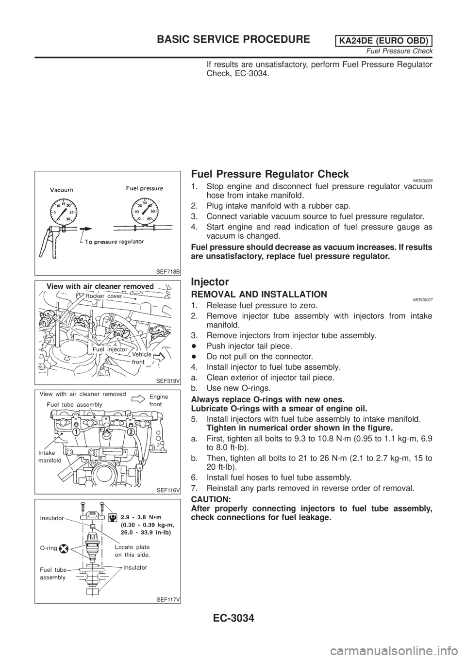
If results are unsatisfactory, perform Fuel Pressure Regulator
Check, EC-3034.
SEF718B
Fuel Pressure Regulator CheckNEEC00261. Stop engine and disconnect fuel pressure regulator vacuum
hose from intake manifold.
2. Plug intake manifold with a rubber cap.
3. Connect variable vacuum source to fuel pressure regulator.
4. Start engine and read indication of fuel pressure gauge as
vacuum is changed.
Fuel pressure should decrease as vacuum increases. If results
are unsatisfactory, replace fuel pressure regulator.
SEF319V
SEF116V
SEF117V
Injector
REMOVAL AND INSTALLATIONNEEC00271. Release fuel pressure to zero.
2. Remove injector tube assembly with injectors from intake
manifold.
3. Remove injectors from injector tube assembly.
+Push injector tail piece.
+Do not pull on the connector.
4. Install injector to fuel tube assembly.
a. Clean exterior of injector tail piece.
b. Use new O-rings.
Always replace O-rings with new ones.
Lubricate O-rings with a smear of engine oil.
5. Install injectors with fuel tube assembly to intake manifold.
Tighten in numerical order shown in the figure.
a. First, tighten all bolts to 9.3 to 10.8 N´m (0.95 to 1.1 kg-m, 6.9
to 8.0 ft-lb).
b. Then, tighten all bolts to 21 to 26 N´m (2.1 to 2.7 kg-m, 15 to
20 ft-lb).
6. Install fuel hoses to fuel tube assembly.
7. Reinstall any parts removed in reverse order of removal.
CAUTION:
After properly connecting injectors to fuel tube assembly,
check connections for fuel leakage.
BASIC SERVICE PROCEDUREKA24DE (EURO OBD)
Fuel Pressure Check
EC-3034
Page 60 of 1306

SEF500V
Fast Idle Cam (FIC)
COMPONENT DESCRIPTIONNEEC0502The FIC is installed on the throttle body to maintain adequate
engine speed while the engine is cold. It is operated by a volumet-
ric change in wax located inside the thermo-element. The thermo-
element is operated by engine coolant temperature.
For inspection refer to ªTROUBLE DIAGNOSIS-BASIC
INSPECTIONº, ªBasic Inspectionº, EC-3086.
Idle Speed/Ignition Timing/Idle Mixture Ratio
Adjustment
NEEC0028PREPARATIONNEEC0028S05+Make sure that the following parts are in good order.
a)Battery
b)Ignition system
c)Engine oil and coolant levels
d)Fuses
e)ECM harness connector
f)Vacuum hoses
g)Air intake system
(Oil filler cap, oil level gauge, etc.)
h)Fuel pressure
i)Engine compression
j)Throttle valve
k)EVAP system
+On models equipped with air conditioner, checks should be carried out while the air conditioner is
ªOFFº.
+When measuring ªCOº percentage, insert probe more than 40 cm (15.7 in) into tail pipe.
+Turn off headlamps, heater blower.
+Keep front wheels pointed straight ahead.
BASIC SERVICE PROCEDUREKA24DE (EURO OBD)
Fast Idle Cam (FIC)
EC-3035
Page 102 of 1306
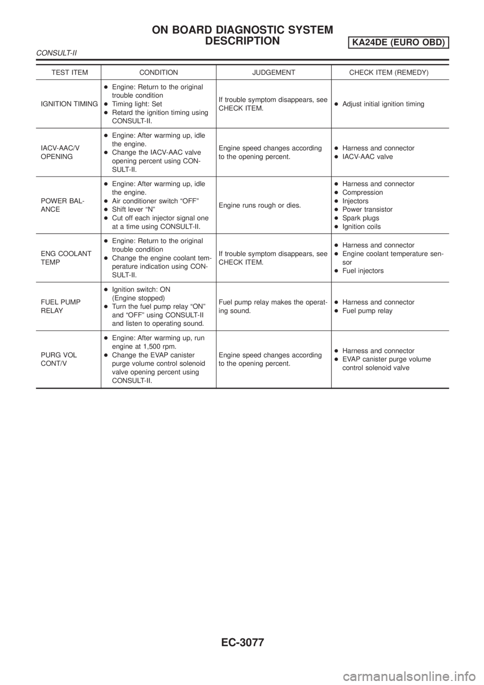
TEST ITEM CONDITION JUDGEMENT CHECK ITEM (REMEDY)
IGNITION TIMING+Engine: Return to the original
trouble condition
+Timing light: Set
+Retard the ignition timing using
CONSULT-II.If trouble symptom disappears, see
CHECK ITEM.+Adjust initial ignition timing
IACV-AAC/V
OPENING+Engine: After warming up, idle
the engine.
+Change the IACV-AAC valve
opening percent using CON-
SULT-II.Engine speed changes according
to the opening percent.+Harness and connector
+IACV-AAC valve
POWER BAL-
ANCE+Engine: After warming up, idle
the engine.
+Air conditioner switch ªOFFº
+Shift lever ªNº
+Cut off each injector signal one
at a time using CONSULT-II.Engine runs rough or dies.+Harness and connector
+Compression
+Injectors
+Power transistor
+Spark plugs
+Ignition coils
ENG COOLANT
TEMP+Engine: Return to the original
trouble condition
+Change the engine coolant tem-
perature indication using CON-
SULT-II.If trouble symptom disappears, see
CHECK ITEM.+Harness and connector
+Engine coolant temperature sen-
sor
+Fuel injectors
FUEL PUMP
RELAY+Ignition switch: ON
(Engine stopped)
+Turn the fuel pump relay ªONº
and ªOFFº using CONSULT-II
and listen to operating sound.Fuel pump relay makes the operat-
ing sound.+Harness and connector
+Fuel pump relay
PURG VOL
CONT/V+Engine: After warming up, run
engine at 1,500 rpm.
+Change the EVAP canister
purge volume control solenoid
valve opening percent using
CONSULT-II.Engine speed changes according
to the opening percent.+Harness and connector
+EVAP canister purge volume
control solenoid valve
ON BOARD DIAGNOSTIC SYSTEM
DESCRIPTION
KA24DE (EURO OBD)
CONSULT-II
EC-3077
Page 289 of 1306
SEF956N
SEF335V
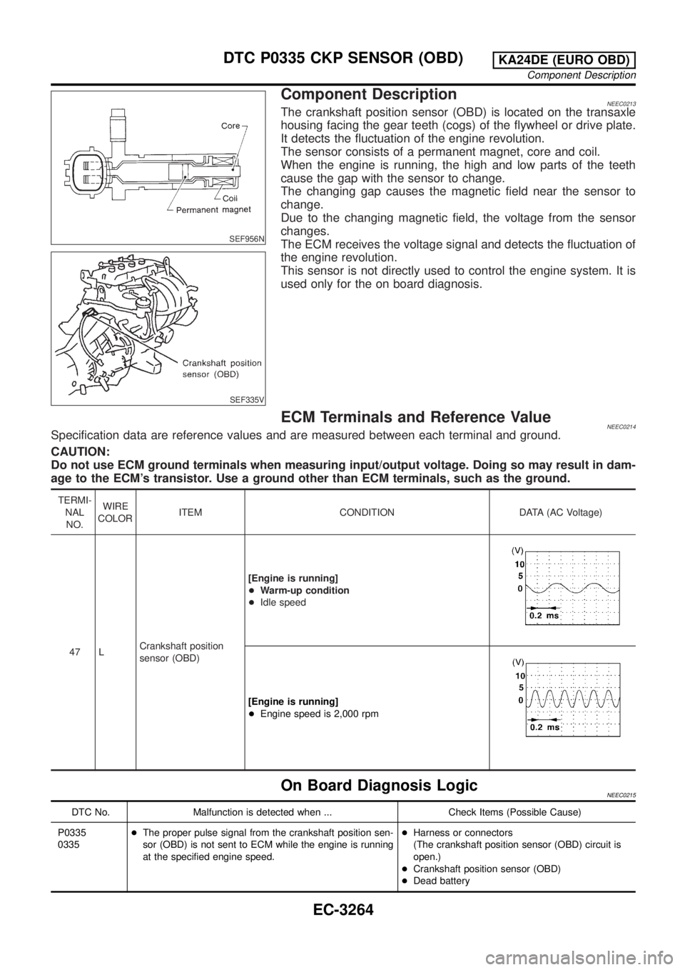
Component DescriptionNEEC0213The crankshaft position sensor (OBD) is located on the transaxle
housing facing the gear teeth (cogs) of the flywheel or drive plate.
It detects the fluctuation of the engine revolution.
The sensor consists of a permanent magnet, core and coil.
When the engine is running, the high and low parts of the teeth
cause the gap with the sensor to change.
The changing gap causes the magnetic field near the sensor to
change.
Due to the changing magnetic field, the voltage from the sensor
changes.
The ECM receives the voltage signal and detects the fluctuation of
the engine revolution.
This sensor is not directly used to control the engine system. It is
used only for the on board diagnosis.
ECM Terminals and Reference ValueNEEC0214Specification data are reference values and are measured between each terminal and ground.
CAUTION:
Do not use ECM ground terminals when measuring input/output voltage. Doing so may result in dam-
age to the ECM's transistor. Use a ground other than ECM terminals, such as the ground.
TERMI-
NAL
NO.WIRE
COLORITEM CONDITION DATA (AC Voltage)
47 LCrankshaft position
sensor (OBD)[Engine is running]
+Warm-up condition
+Idle speed
[Engine is running]
+Engine speed is 2,000 rpm
On Board Diagnosis LogicNEEC0215
DTC No. Malfunction is detected when ... Check Items (Possible Cause)
P0335
0335+The proper pulse signal from the crankshaft position sen-
sor (OBD) is not sent to ECM while the engine is running
at the specified engine speed.+Harness or connectors
(The crankshaft position sensor (OBD) circuit is
open.)
+Crankshaft position sensor (OBD)
+Dead battery
DTC P0335 CKP SENSOR (OBD)KA24DE (EURO OBD)
Component Description
EC-3264
Page 374 of 1306
SEF956N
SEF335V
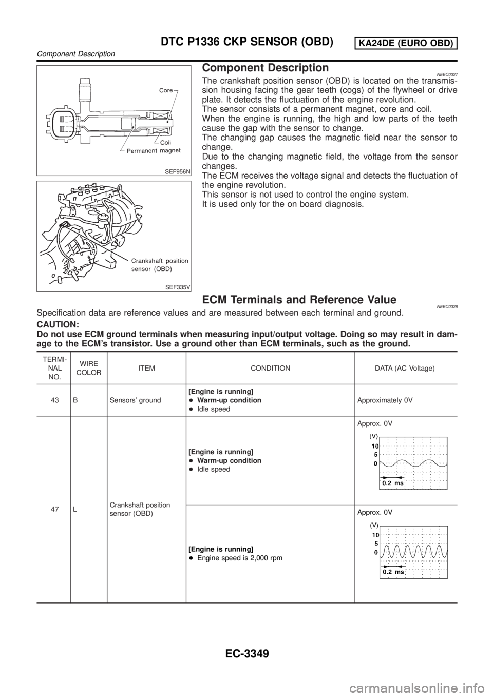
Component DescriptionNEEC0327The crankshaft position sensor (OBD) is located on the transmis-
sion housing facing the gear teeth (cogs) of the flywheel or drive
plate. It detects the fluctuation of the engine revolution.
The sensor consists of a permanent magnet, core and coil.
When the engine is running, the high and low parts of the teeth
cause the gap with the sensor to change.
The changing gap causes the magnetic field near the sensor to
change.
Due to the changing magnetic field, the voltage from the sensor
changes.
The ECM receives the voltage signal and detects the fluctuation of
the engine revolution.
This sensor is not used to control the engine system.
It is used only for the on board diagnosis.
ECM Terminals and Reference ValueNEEC0328Specification data are reference values and are measured between each terminal and ground.
CAUTION:
Do not use ECM ground terminals when measuring input/output voltage. Doing so may result in dam-
age to the ECM's transistor. Use a ground other than ECM terminals, such as the ground.
TERMI-
NAL
NO.WIRE
COLORITEM CONDITION DATA (AC Voltage)
43 B Sensors' ground[Engine is running]
+Warm-up condition
+Idle speedApproximately 0V
47 LCrankshaft position
sensor (OBD)[Engine is running]
+Warm-up condition
+Idle speedApprox. 0V
[Engine is running]
+Engine speed is 2,000 rpmApprox. 0V
DTC P1336 CKP SENSOR (OBD)KA24DE (EURO OBD)
Component Description
EC-3349
Page 1035 of 1306
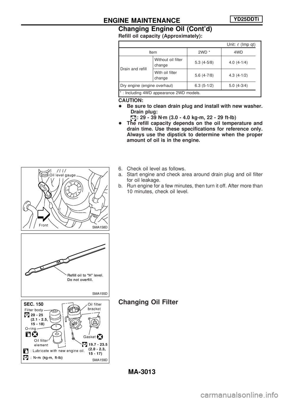
Refill oil capacity (Approximately):
Unit:!(Imp qt)
Item 2WD * 4WD
Drain and refillWithout oil filter
change5.3 (4-5/8) 4.0 (4-1/4)
With oil filter
change5.6 (4-7/8) 4.3 (4-1/2)
Dry engine (engine overhaul) 6.3 (5-1/2) 5.0 (4-3/4)
* : Including 4WD appearance 2WD models.
CAUTION:
+Be sure to clean drain plug and install with new washer.
Drain plug:
:29-39Nzm (3.0 - 4.0 kg-m, 22 - 29 ft-lb)
+The refill capacity depends on the oil temperature and
drain time. Use these specifications for reference only.
Always use the dipstick to determine when the proper
amount of oil is in the engine.
6. Check oil level as follows.
a. Start engine and check area around drain plug and oil filter
for oil leakage.
b. Run engine for a few minutes, then turn it off. After more than
10 minutes, check oil level.
Changing Oil Filter
SMA158D
SMA155D
SMA159D
ENGINE MAINTENANCEYD25DDTi
Changing Engine Oil (Cont'd)
MA-3013
Page 1036 of 1306
![NISSAN PICK-UP 2001 Repair Manual REMOVAL
1. Place a pan to catch the oil under the lower part of drain hose
outlet before removing filter body.
2. Using a hexagonal socket wrench [plane-to-plane width: 24
mm (0.94 in)], loosen the fi NISSAN PICK-UP 2001 Repair Manual REMOVAL
1. Place a pan to catch the oil under the lower part of drain hose
outlet before removing filter body.
2. Using a hexagonal socket wrench [plane-to-plane width: 24
mm (0.94 in)], loosen the fi](/manual-img/5/57372/w960_57372-1035.png)
REMOVAL
1. Place a pan to catch the oil under the lower part of drain hose
outlet before removing filter body.
2. Using a hexagonal socket wrench [plane-to-plane width: 24
mm (0.94 in)], loosen the filter body approximately four turns.
3. Remove the filter body, then remove the oil filter element.
4. Remove the O-ring from the filter body.
+Push the O-ring in one direction, lift the slack part using
fingers, and remove the O-ring from the filter body.
CAUTION:
Do not use wires or flat-bladed screwdrivers etc. as they
may cause damage to the filter body.
INSTALLATION
1. Completely remove all foreign objects adhering to the inside
of the filter body or O-ring mounting area (filter body side and
bracket side).
2. Install the oil filter element and O-ring to the filter body.
+Push the oil filter element into the filter body completely.
3. Install the filter body to the oil filter bracket.
:20-25Nzm (2.0 - 2.6 kg-m, 15 - 18 ft-lb)
4. After warming up the engine, check for engine oil leakage
and oil level.
CAUTION:
Completely wipe clean any engine oil remaining on the fil-
ter body or vehicle.
Changing Engine Coolant
To avoid the danger of being scalded, never change the
coolant when the engine is hot.
Ð DRAINING ENGINE COOLANT Ð
1. Set air conditioning system as follows to prevent coolant from
remaining in the system.
a. Turn ignition switch ON and set temperature controller to
maximum hot position.
b. Wait 10 seconds before turning ignition switch OFF.
2. Open radiator drain plug at the bottom of radiator and
remove radiator cap to drain coolant.
SMA160D
JLC292B OK
SMA161D
ENGINE MAINTENANCEYD25DDTi
Changing Oil Filter (Cont'd)
MA-3014
Page 1064 of 1306
Injection nozzle ........................... EC-3415, 3416
Injector removal and installation ........... EC-3034
Intake air temperature
sensor ................. EC-3160, 3193, 3503, 3504
Intake manifold ..................................... EM-3008
Interior lamp ........................................... EL-3054
K
KS - Wiring diagram ............................. EC-3261
Keyless entry system - See Multi-re-
mote control system .......................... EL-3136
Knock sensor (KS) ...................... EC-3260, 3261
L
License lampEL148Parking lamp .......... EL-3039
Liquid gasket application ...................... EM-3003
Location of electrical units ..................... EL-3163
Lubricants ............................................. MA-3008
Lubrication circuit (engine) .................... LC-3003
M
M/T removal and installation ................ MT-3002
MAFS - Wiring diagram .............. EC-3146, 3154
MAIN - Wiring diagram ..... EC-3124, 3470, 3471
METER - Wiring diagram ...................... EL-3062
MIL & Data link connectors circuit ........ EC-3396
MIL/DL - Wiring diagram .. EC-3396, 3646, 3647
MIRROR - Wiring diagram .................... EL-3116
MULTI - Wiring diagram ........................ EL-3137
Main gear (Transfer) .............................. TF-3004
Mainshaft (Transfer) .............................. TF-3004
Maintenance (engine) ................. MA-3010, 3011
Malfunction indicator lamp
(MIL) ........................................ EC-3429, 3430
Manifold tightening torque (intake &
exhaust) ............................................ MA-3011
Mass air flow sensor
(MAFS) .................... DT-3143, EC-3143, 3151
Meter ...................................................... EL-3056
Misfire .................................................... EC-3251
Model variation ....................................... GI-3004
Mud guard - See Exterior ...................... BT-3006
Multi-remote control system .................. EL-3136
Multiport fuel injection (MFI) system ..... EC-3024
N
NATS (Nissan Anti-theft System) .......... EL-3143
NATS - Wiring diagram ......................... EL-3146
Neutral position switch .......................... EC-3355
O
Oil change (capacity) ............................ MA-3008
Oil cooler (engine) ................................. LC-3006
Oil pan (engine) .................................... EM-3015
Oil pressure (engine) ............................. LC-3004
Oil pump (engine) .................................. LC-3004
Oil pump regulator valve (engine) ......... LC-3005
On board diagnostic
system ........................... EC-3049, 3428, 3429
P
P/ANT - Wiring diagram ........................ EL-3115
PCV (positive crankcase
ventilation) ..................... EC-3032, 3414, 3415
PCV filter replacement ......................... MA-3010
PGC/V - Wiring diagram ....................... EC-3286
PNP/SW - Wiring diagram .................... EC-3358
POWER - Wiring diagram ..................... EL-3006
PST/SW - Wiring diagram .................... EC-3386
Park/Neutral position
switch ............................ EC-3355, 3633, 3634
Parking lamp .......................................... EL-3039
Piston assembly ................................... EM-3081
Piston pin inspection ............................ EM-3071
Piston ring inspection ........................... EM-3071
Piston to bore clearance ...................... EM-3073
Power door mirror .................................. EL-3116
Power steering oil pressure switch ....... EC-3385
Power supply routing ............................. EL-3005
Power transistor & ignition coil ............. EC-3361
Power window ....................................... EL-3120
Priming pump .............................. EC-3444, 3445
Q
Quick-glow system ...................... EC-3621, 3622
R
R/FOG - Wiring diagram ....................... EL-3045
ROOM/L - Wiring diagram ..................... EL-3054
Radiator fan - See Cooling fan ............. LC-3016
Radiator ................................................. LC-3015
Rear case (Transfer) ............................. TF-3003
Rear fog lamp ........................................ EL-3045
Rear window defogger .......................... EL-3112
Refrigerant connection precaution ........ HA-3002
Refrigerant lines .................................... HA-3030
Road wheel size ..................................... GI-3007
Room lamp ............................................ EL-3054
ALPHABETICAL INDEX
IDX-3004