2001 NISSAN PICK-UP fog light
[x] Cancel search: fog lightPage 144 of 1306
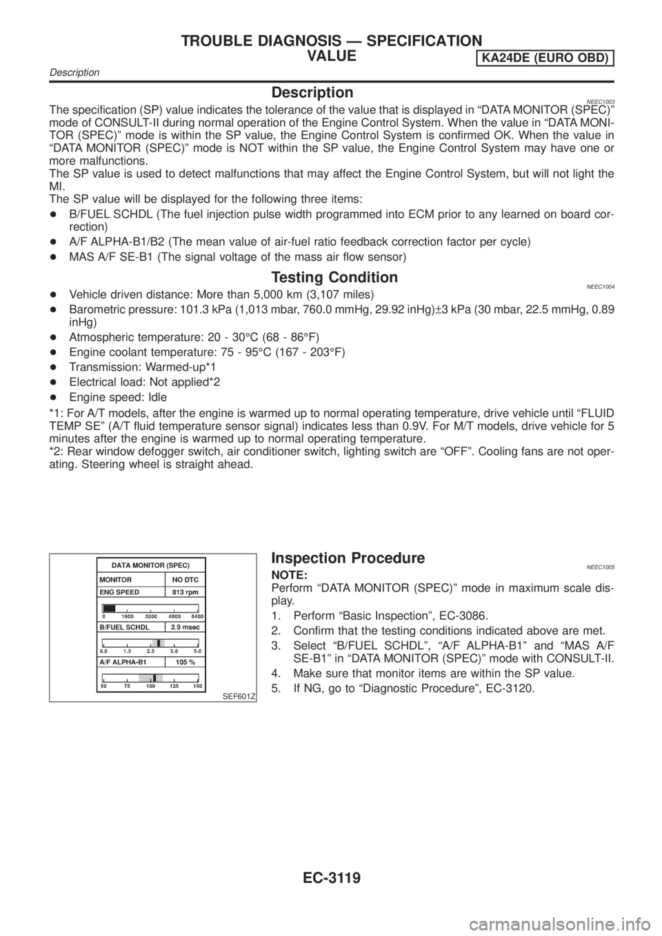
DescriptionNEEC1003The specification (SP) value indicates the tolerance of the value that is displayed in ªDATA MONITOR (SPEC)º
mode of CONSULT-II during normal operation of the Engine Control System. When the value in ªDATA MONI-
TOR (SPEC)º mode is within the SP value, the Engine Control System is confirmed OK. When the value in
ªDATA MONITOR (SPEC)º mode is NOT within the SP value, the Engine Control System may have one or
more malfunctions.
The SP value is used to detect malfunctions that may affect the Engine Control System, but will not light the
MI.
The SP value will be displayed for the following three items:
+B/FUEL SCHDL (The fuel injection pulse width programmed into ECM prior to any learned on board cor-
rection)
+A/F ALPHA-B1/B2 (The mean value of air-fuel ratio feedback correction factor per cycle)
+MAS A/F SE-B1 (The signal voltage of the mass air flow sensor)
Testing ConditionNEEC1004+Vehicle driven distance: More than 5,000 km (3,107 miles)
+Barometric pressure: 101.3 kPa (1,013 mbar, 760.0 mmHg, 29.92 inHg)±3 kPa (30 mbar, 22.5 mmHg, 0.89
inHg)
+Atmospheric temperature: 20 - 30ÉC (68 - 86ÉF)
+Engine coolant temperature: 75 - 95ÉC (167 - 203ÉF)
+Transmission: Warmed-up*1
+Electrical load: Not applied*2
+Engine speed: Idle
*1: For A/T models, after the engine is warmed up to normal operating temperature, drive vehicle until ªFLUID
TEMP SEº (A/T fluid temperature sensor signal) indicates less than 0.9V. For M/T models, drive vehicle for 5
minutes after the engine is warmed up to normal operating temperature.
*2: Rear window defogger switch, air conditioner switch, lighting switch are ªOFFº. Cooling fans are not oper-
ating. Steering wheel is straight ahead.
SEF601Z
Inspection ProcedureNEEC1005NOTE:
Perform ªDATA MONITOR (SPEC)º mode in maximum scale dis-
play.
1. Perform ªBasic Inspectionº, EC-3086.
2. Confirm that the testing conditions indicated above are met.
3. Select ªB/FUEL SCHDLº, ªA/F ALPHA-B1º and ªMAS A/F
SE-B1º in ªDATA MONITOR (SPEC)º mode with CONSULT-II.
4. Make sure that monitor items are within the SP value.
5. If NG, go to ªDiagnostic Procedureº, EC-3120.
TROUBLE DIAGNOSIS Ð SPECIFICATION
VALUE
KA24DE (EURO OBD)
Description
EC-3119
Page 423 of 1306
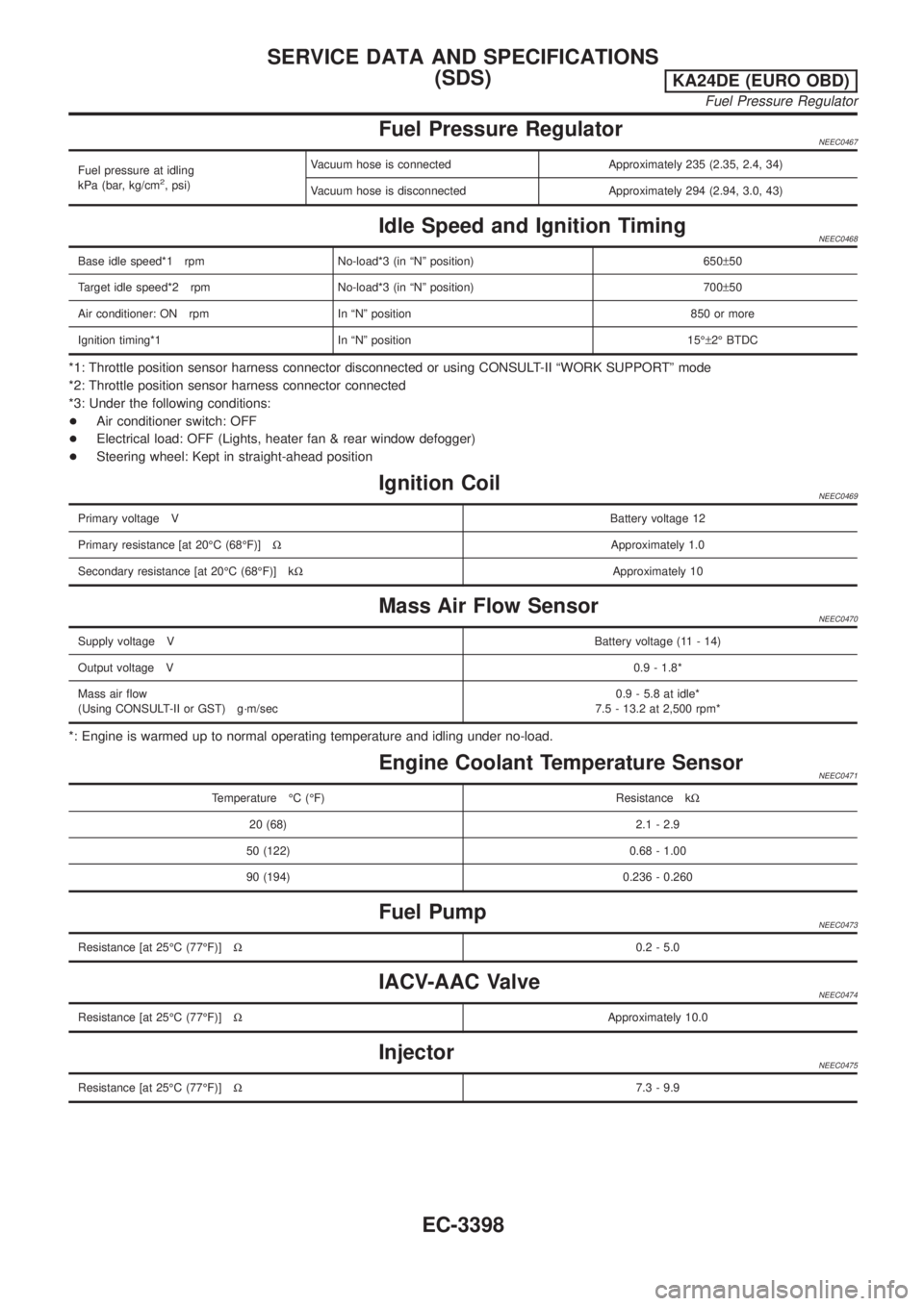
Fuel Pressure RegulatorNEEC0467
Fuel pressure at idling
kPa (bar, kg/cm2, psi)Vacuum hose is connected Approximately 235 (2.35, 2.4, 34)
Vacuum hose is disconnected Approximately 294 (2.94, 3.0, 43)
Idle Speed and Ignition TimingNEEC0468
Base idle speed*1 rpm No-load*3 (in ªNº position) 650±50
Target idle speed*2 rpm No-load*3 (in ªNº position) 700±50
Air conditioner: ON rpm In ªNº position 850 or more
Ignition timing*1 In ªNº position 15ɱ2É BTDC
*1: Throttle position sensor harness connector disconnected or using CONSULT-II ªWORK SUPPORTº mode
*2: Throttle position sensor harness connector connected
*3: Under the following conditions:
+Air conditioner switch: OFF
+Electrical load: OFF (Lights, heater fan & rear window defogger)
+Steering wheel: Kept in straight-ahead position
Ignition CoilNEEC0469
Primary voltage VBattery voltage 12
Primary resistance [at 20ÉC (68ÉF)]WApproximately 1.0
Secondary resistance [at 20ÉC (68ÉF)] kWApproximately 10
Mass Air Flow SensorNEEC0470
Supply voltage VBattery voltage (11 - 14)
Output voltage V0.9 - 1.8*
Mass air flow
(Using CONSULT-II or GST) g´m/sec0.9 - 5.8 at idle*
7.5 - 13.2 at 2,500 rpm*
*: Engine is warmed up to normal operating temperature and idling under no-load.
Engine Coolant Temperature SensorNEEC0471
Temperature ÉC (ÉF) Resistance kW
20 (68) 2.1 - 2.9
50 (122) 0.68 - 1.00
90 (194) 0.236 - 0.260
Fuel PumpNEEC0473
Resistance [at 25ÉC (77ÉF)]W0.2 - 5.0
IACV-AAC ValveNEEC0474
Resistance [at 25ÉC (77ÉF)]WApproximately 10.0
InjectorNEEC0475
Resistance [at 25ÉC (77ÉF)]W7.3 - 9.9
SERVICE DATA AND SPECIFICATIONS
(SDS)
KA24DE (EURO OBD)
Fuel Pressure Regulator
EC-3398
Page 676 of 1306

ELECTRICAL SYSTEM
SECTION
EL
MODIFICATION NOTICE:
+Wiring diagrams have been changed.
+Combination meter has been changed.
+Headlamp has been changed.
+Headlamp aiming control has been added.
+Headlamp washer has been added.
+A hazard reminder feature has been added to the multi-remote control system.
+NATS (Nissan Anti-Theft System) has been changed.
CONTENTS
PRECAUTIONS................................................... 3004
Supplemental Restraint System (SRS)²AIR
BAG²and²SEAT BELT PRE-TENSIONER².. 3004
POWER SUPPLY ROUTING............................... 3005
Schematic ........................................................ 3005
Wiring Diagram - POWER -............................. 3006
BATTERY............................................................. 3013
Service Data and Specifications (SDS) ........... 3013
STARTING SYSTEM........................................... 3014
Wiring Diagram - START -/M/T Models .......... 3014
Construction ..................................................... 3015
Service Data and Specifications (SDS) ........... 3017
CHARGING SYSTEM.......................................... 3018
Wiring Diagram - CHARGE -/Diesel Engine ... 3018
Wiring Diagram - CHARGE - (KA engine) ...... 3019
Construction ..................................................... 3020
Service Data and Specifications (SDS) ........... 3022
HEADLAMP - Conventional Type -................... 3023
Wiring Diagram - H/LAMP -/LHD Models ........ 3023
Wiring Diagram - H/LAMP -/RHD Models ....... 3025
Bulb Replacement............................................ 3027
Aiming Adjustment ........................................... 3027
Low Beam ........................................................ 3028
HEADLAMP - Daytime Light System -............. 3029
Wiring Diagram - DTRL - ................................. 3029
Bulb Replacement............................................ 3032
Aiming Adjustment ........................................... 3032
HEADLAMP - Dim-dip Lamp System -............. 3033Wiring Diagram - DIMDIP -.............................. 3033
Bulb Replacement............................................ 3036
Aiming Adjustment ........................................... 3036
HEADLAMP - Headlamp Aiming Control -....... 3037
Wiring Diagram - H/AIM - ................................ 3037
PARKING, LICENSE AND TAIL LAMPS........... 3039
Wiring Diagram - TAIL/L -/Except LHD Models
for Europe ........................................................ 3039
Wiring Diagram - TAIL/L -/LHD Models for
Europe.............................................................. 3041
STOP LAMP........................................................ 3043
Wiring Diagram - STOP/L - ............................. 3043
BACK-UP LAMP.................................................. 3044
Wiring Diagram - BACK/L -/M/T Models ......... 3044
REAR FOG LAMP............................................... 3045
Wiring Diagram - R/FOG -/LHD Models .......... 3045
Wiring Diagram - R/FOG -/RHD Models ......... 3046
TURN SIGNAL AND HAZARD WARNING
LAMPS................................................................. 3047
Wiring Diagram - TURN - ................................ 3047
Trouble Diagnoses ........................................... 3049
ILLUMINATION.................................................... 3050
Wiring Diagram - ILL -/LHD Models ................ 3050
Wiring Diagram - ILL -/RHD Models................ 3052
INTERIOR ROOM LAMP..................................... 3054
Wiring Diagram - ROOM/L - ............................ 3054
SPOT LAMP........................................................ 3055
Wiring Diagram - INT/L - ................................. 3055
EL
Page 677 of 1306

METER AND GAUGES....................................... 3056
System Description .......................................... 3056
Combination Meter/With Tachometer .............. 3057
Combination Meter/Without Tachometer ......... 3058
Schematic/With Tachometer ............................ 3059
Schematic/Without Tachometer ....................... 3060
Construction ..................................................... 3061
Wiring Diagram - METER -/Gasoline Engine
with Tachometer .............................................. 3062
Wiring Diagram - METER -/Gasoline Engine
without Tachometer ......................................... 3064
Wiring Diagram - METER -/LHD Diesel Engine
Models with Tachometer.................................. 3065
Wiring Diagram - METER -/RHD Diesel
Engine Models with Tachometer ..................... 3067
Wiring Diagram - METER -/Diesel Engine
without Tachometer ......................................... 3069
Meter/Gauge Operation and Odo/Trip Meter
Segment Check in Diagnosis Mode ................ 3070
Trouble Diagnoses/With Tachometer .............. 3071
Trouble Diagnoses/Without Tachometer ......... 3076
WARNING LAMPS.............................................. 3081
Schematic/With Tachometer ............................ 3081
Schematic/Without Tachometer ....................... 3082
Wiring Diagram - WARN -/Gasoline Engine
with Tachometer .............................................. 3083
Wiring Diagram - WARN -/Gasoline Engine
without Tachometer ......................................... 3087
Wiring Diagram - WARN -/Diesel Engine with
Tachometer ...................................................... 3091
Wiring Diagram - WARN -/Diesel Engine
without Tachometer ......................................... 3095
A/T INDICATOR................................................... 3100
Wiring Diagram - AT/IND -/RHD Models ......... 3100
Wiring Diagram - CHIME -/LHD Models.......... 3101
Wiring Diagram - CHIME -/RHD Models ......... 3102
FRONT WIPER AND WASHER.......................... 3103
Wiring Diagram - WIPER -/Without Intermittent
for Floor-shift .................................................... 3103
Wiring Diagram - WIPER -/Without Intermittent
for RHD Column-shift Models .......................... 3106
HEADLAMP WASHER........................................ 3108
Wiring Diagram - HLC - ................................... 3108
HORN................................................................... 3109
Wiring Diagram - HORN -................................ 3109
CIGARETTE LIGHTER........................................ 3110
Wiring Diagram - CIGAR - ............................... 3110
CLOCK................................................................. 3111
Wiring Diagram - CLOCK - .............................. 3111
REAR WINDOW DEFOGGER AND MIRROR
DEFOGGER......................................................... 3112
Wiring Diagram - DEF - ................................... 3112
AUDIO.................................................................. 3113
Wiring Diagram - AUDIO -/LHD Models .......... 3113Wiring Diagram - AUDIO -/RHD Models ......... 3114
AUDIO ANTENNA............................................... 3115
Power Antenna/Wiring Diagram - P/ANT - ...... 3115
POWER DOOR MIRROR.................................... 3116
Wiring Diagram - MIRROR -/LHD Models....... 3116
Wiring Diagram - MIRROR -/RHD Models ...... 3117
HEATED SEAT.................................................... 3118
Wiring Diagram - H/SEAT - ............................. 3118
POWER WINDOW............................................... 3120
Schematic/Without Interruption Detection
Function ........................................................... 3120
Schematic/With Interruption Detection
Function ........................................................... 3121
Wiring Diagram - WINDOW -/Without
Interruption Detection Function........................ 3122
Wiring Diagram - WINDOW -/With Interruption
Detection Function ........................................... 3126
Trouble Diagnoses/Without Interruption
Detection Function ........................................... 3130
Trouble Diagnoses/With Interruption Detection
Function ........................................................... 3131
POWER DOOR LOCK......................................... 3133
Wiring Diagram - D/LOCK - ............................. 3133
MULTI-REMOTE CONTROL SYSTEM............... 3135
System Description .......................................... 3135
MULTI-REMOTE CONTROL SYSTEM............... 3136
Wiring Diagram - MULTI - ............................... 3136
Trouble Diagnoses ........................................... 3137
ID Code Entry Procedure ................................ 3139
Remote Controller Battery Replacement ......... 3140
THEFT WARNING SYSTEM............................... 3141
Wiring Diagram - PRWIRE - ............................ 3141
NATS (Nissan Anti-Theft System).................... 3142
Component Parts and Harness Connector
Location............................................................ 3142
System Description .......................................... 3143
System Composition ........................................ 3144
Wiring Diagram - NATS -/LHD Models............ 3145
Wiring Diagram - NATS -/RHD Diesel Engine
Models.............................................................. 3146
CONSULT-II ..................................................... 3147
Trouble Diagnoses ........................................... 3149
How to Replace NATS IMMU .......................... 3160
LOCATION OF ELECTRICAL UNITS................. 3161
Engine Compartment ....................................... 3161
Passenger Compartment ................................. 3162
HARNESS LAYOUT............................................ 3164
Main Harness ................................................... 3164
Engine Room Harness..................................... 3174
Engine Control Harness/KA engine ................. 3182
Engine Control Harness................................... 3184
Engine Harness ............................................... 3185
Alternator Harness ........................................... 3187
Instrument Harness.......................................... 3189
EL-3002
Page 869 of 1306
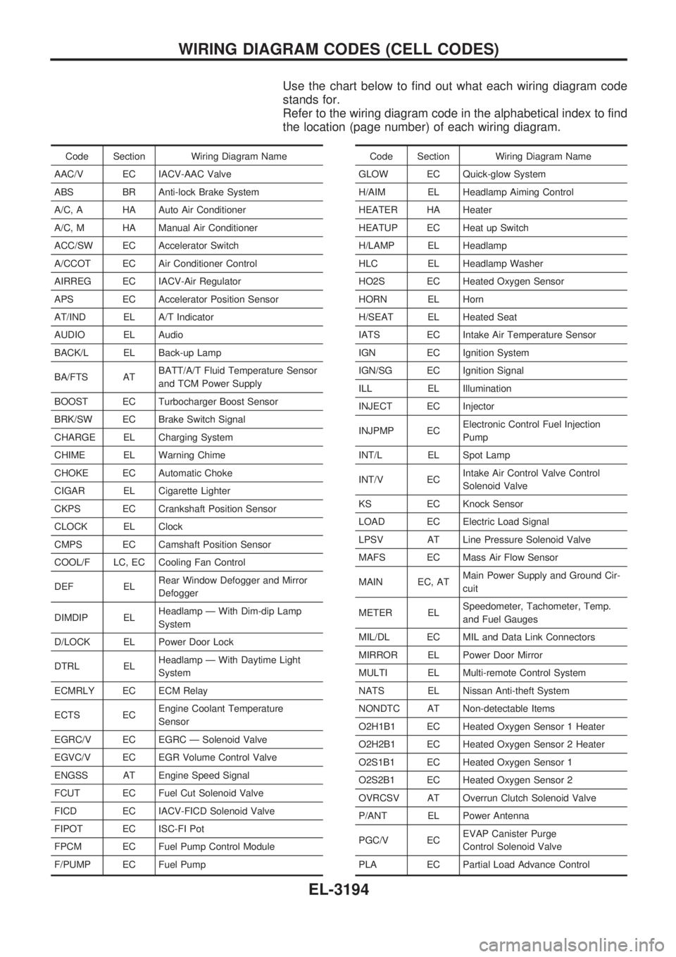
Use the chart below to find out what each wiring diagram code
stands for.
Refer to the wiring diagram code in the alphabetical index to find
the location (page number) of each wiring diagram.
Code Section Wiring Diagram Name
AAC/V EC IACV-AAC Valve
ABS BR Anti-lock Brake System
A/C, A HA Auto Air Conditioner
A/C, M HA Manual Air Conditioner
ACC/SW EC Accelerator Switch
A/CCOT EC Air Conditioner Control
AIRREG EC IACV-Air Regulator
APS EC Accelerator Position Sensor
AT/IND EL A/T Indicator
AUDIO EL Audio
BACK/L EL Back-up Lamp
BA/FTS ATBATT/A/T Fluid Temperature Sensor
and TCM Power Supply
BOOST EC Turbocharger Boost Sensor
BRK/SW EC Brake Switch Signal
CHARGE EL Charging System
CHIME EL Warning Chime
CHOKE EC Automatic Choke
CIGAR EL Cigarette Lighter
CKPS EC Crankshaft Position Sensor
CLOCK EL Clock
CMPS EC Camshaft Position Sensor
COOL/F LC, EC Cooling Fan Control
DEF ELRear Window Defogger and Mirror
Defogger
DIMDIP ELHeadlamp Ð With Dim-dip Lamp
System
D/LOCK EL Power Door Lock
DTRL ELHeadlamp Ð With Daytime Light
System
ECMRLY EC ECM Relay
ECTS ECEngine Coolant Temperature
Sensor
EGRC/V EC EGRC Ð Solenoid Valve
EGVC/V EC EGR Volume Control Valve
ENGSS AT Engine Speed Signal
FCUT EC Fuel Cut Solenoid Valve
FICD EC IACV-FICD Solenoid Valve
FIPOT EC ISC-FI Pot
FPCM EC Fuel Pump Control Module
F/PUMP EC Fuel PumpCode Section Wiring Diagram Name
GLOW EC Quick-glow System
H/AIM EL Headlamp Aiming Control
HEATER HA Heater
HEATUP EC Heat up Switch
H/LAMP EL Headlamp
HLC EL Headlamp Washer
HO2S EC Heated Oxygen Sensor
HORN EL Horn
H/SEAT EL Heated Seat
IATS EC Intake Air Temperature Sensor
IGN EC Ignition System
IGN/SG EC Ignition Signal
ILL EL Illumination
INJECT EC Injector
INJPMP ECElectronic Control Fuel Injection
Pump
INT/L EL Spot Lamp
INT/V ECIntake Air Control Valve Control
Solenoid Valve
KS EC Knock Sensor
LOAD EC Electric Load Signal
LPSV AT Line Pressure Solenoid Valve
MAFS EC Mass Air Flow Sensor
MAIN EC, ATMain Power Supply and Ground Cir-
cuit
METER ELSpeedometer, Tachometer, Temp.
and Fuel Gauges
MIL/DL EC MIL and Data Link Connectors
MIRROR EL Power Door Mirror
MULTI EL Multi-remote Control System
NATS EL Nissan Anti-theft System
NONDTC AT Non-detectable Items
O2H1B1 EC Heated Oxygen Sensor 1 Heater
O2H2B1 EC Heated Oxygen Sensor 2 Heater
O2S1B1 EC Heated Oxygen Sensor 1
O2S2B1 EC Heated Oxygen Sensor 2
OVRCSV AT Overrun Clutch Solenoid Valve
P/ANT EL Power Antenna
PGC/V ECEVAP Canister Purge
Control Solenoid Valve
PLA EC Partial Load Advance Control
WIRING DIAGRAM CODES (CELL CODES)
EL-3194
Page 1112 of 1306
ELECTRICAL SYSTEM
SECTION
EL
MODIFICATION NOTICE:
+Wiring diagrams have been changed.
+Combination meter has been changed.
+Headlamp has been changed.
+Headlamp aiming control has been added.
+Headlamp washer has been added.
+A hazard reminder feature has been added to the multi-remote control system.
+NATS (Nissan Anti-Theft System) has been changed.
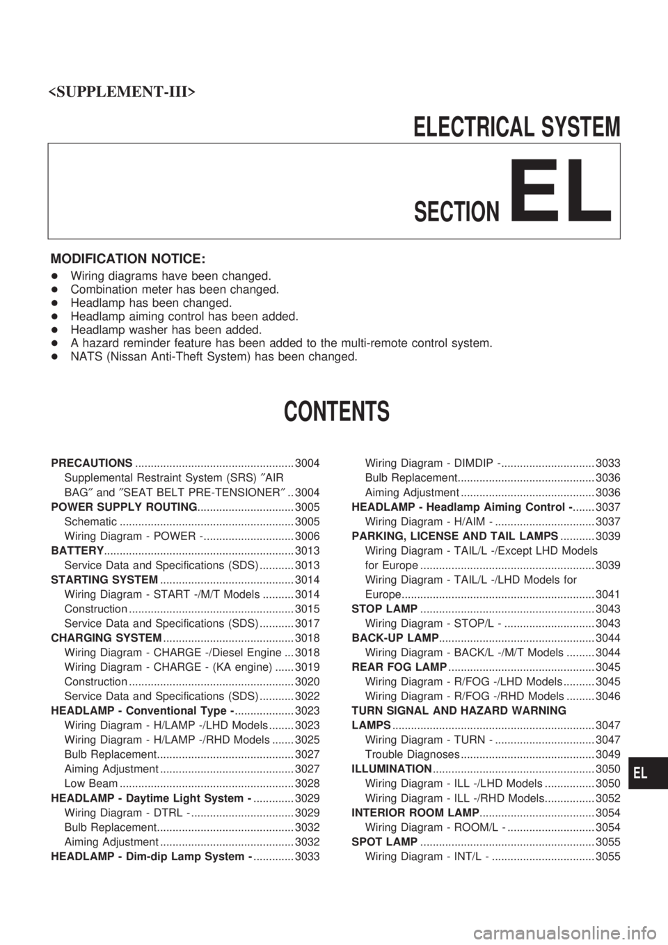
CONTENTS
PRECAUTIONS................................................... 3004
Supplemental Restraint System (SRS)²AIR
BAG²and²SEAT BELT PRE-TENSIONER².. 3004
POWER SUPPLY ROUTING............................... 3005
Schematic ........................................................ 3005
Wiring Diagram - POWER -............................. 3006
BATTERY............................................................. 3013
Service Data and Specifications (SDS) ........... 3013
STARTING SYSTEM........................................... 3014
Wiring Diagram - START -/M/T Models .......... 3014
Construction ..................................................... 3015
Service Data and Specifications (SDS) ........... 3017
CHARGING SYSTEM.......................................... 3018
Wiring Diagram - CHARGE -/Diesel Engine ... 3018
Wiring Diagram - CHARGE - (KA engine) ...... 3019
Construction ..................................................... 3020
Service Data and Specifications (SDS) ........... 3022
HEADLAMP - Conventional Type -................... 3023
Wiring Diagram - H/LAMP -/LHD Models ........ 3023
Wiring Diagram - H/LAMP -/RHD Models ....... 3025
Bulb Replacement............................................ 3027
Aiming Adjustment ........................................... 3027
Low Beam ........................................................ 3028
HEADLAMP - Daytime Light System -............. 3029
Wiring Diagram - DTRL - ................................. 3029
Bulb Replacement............................................ 3032
Aiming Adjustment ........................................... 3032
HEADLAMP - Dim-dip Lamp System -............. 3033Wiring Diagram - DIMDIP -.............................. 3033
Bulb Replacement............................................ 3036
Aiming Adjustment ........................................... 3036
HEADLAMP - Headlamp Aiming Control -....... 3037
Wiring Diagram - H/AIM - ................................ 3037
PARKING, LICENSE AND TAIL LAMPS........... 3039
Wiring Diagram - TAIL/L -/Except LHD Models
for Europe ........................................................ 3039
Wiring Diagram - TAIL/L -/LHD Models for
Europe.............................................................. 3041
STOP LAMP........................................................ 3043
Wiring Diagram - STOP/L - ............................. 3043
BACK-UP LAMP.................................................. 3044
Wiring Diagram - BACK/L -/M/T Models ......... 3044
REAR FOG LAMP............................................... 3045
Wiring Diagram - R/FOG -/LHD Models .......... 3045
Wiring Diagram - R/FOG -/RHD Models ......... 3046
TURN SIGNAL AND HAZARD WARNING
LAMPS................................................................. 3047
Wiring Diagram - TURN - ................................ 3047
Trouble Diagnoses ........................................... 3049
ILLUMINATION.................................................... 3050
Wiring Diagram - ILL -/LHD Models ................ 3050
Wiring Diagram - ILL -/RHD Models................ 3052
INTERIOR ROOM LAMP..................................... 3054
Wiring Diagram - ROOM/L - ............................ 3054
SPOT LAMP........................................................ 3055
Wiring Diagram - INT/L - ................................. 3055
EL
Page 1113 of 1306
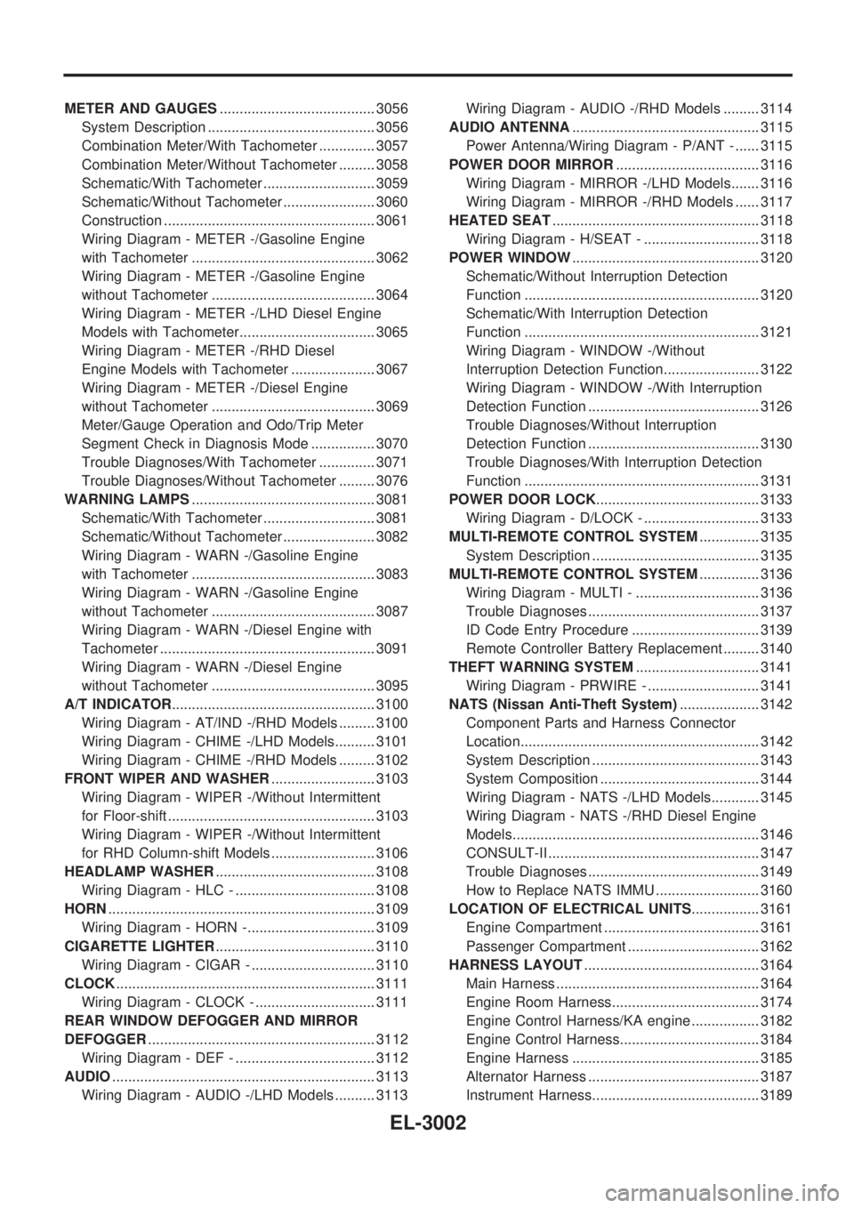
METER AND GAUGES....................................... 3056
System Description .......................................... 3056
Combination Meter/With Tachometer .............. 3057
Combination Meter/Without Tachometer ......... 3058
Schematic/With Tachometer ............................ 3059
Schematic/Without Tachometer ....................... 3060
Construction ..................................................... 3061
Wiring Diagram - METER -/Gasoline Engine
with Tachometer .............................................. 3062
Wiring Diagram - METER -/Gasoline Engine
without Tachometer ......................................... 3064
Wiring Diagram - METER -/LHD Diesel Engine
Models with Tachometer.................................. 3065
Wiring Diagram - METER -/RHD Diesel
Engine Models with Tachometer ..................... 3067
Wiring Diagram - METER -/Diesel Engine
without Tachometer ......................................... 3069
Meter/Gauge Operation and Odo/Trip Meter
Segment Check in Diagnosis Mode ................ 3070
Trouble Diagnoses/With Tachometer .............. 3071
Trouble Diagnoses/Without Tachometer ......... 3076
WARNING LAMPS.............................................. 3081
Schematic/With Tachometer ............................ 3081
Schematic/Without Tachometer ....................... 3082
Wiring Diagram - WARN -/Gasoline Engine
with Tachometer .............................................. 3083
Wiring Diagram - WARN -/Gasoline Engine
without Tachometer ......................................... 3087
Wiring Diagram - WARN -/Diesel Engine with
Tachometer ...................................................... 3091
Wiring Diagram - WARN -/Diesel Engine
without Tachometer ......................................... 3095
A/T INDICATOR................................................... 3100
Wiring Diagram - AT/IND -/RHD Models ......... 3100
Wiring Diagram - CHIME -/LHD Models.......... 3101
Wiring Diagram - CHIME -/RHD Models ......... 3102
FRONT WIPER AND WASHER.......................... 3103
Wiring Diagram - WIPER -/Without Intermittent
for Floor-shift .................................................... 3103
Wiring Diagram - WIPER -/Without Intermittent
for RHD Column-shift Models .......................... 3106
HEADLAMP WASHER........................................ 3108
Wiring Diagram - HLC - ................................... 3108
HORN................................................................... 3109
Wiring Diagram - HORN -................................ 3109
CIGARETTE LIGHTER........................................ 3110
Wiring Diagram - CIGAR - ............................... 3110
CLOCK................................................................. 3111
Wiring Diagram - CLOCK - .............................. 3111
REAR WINDOW DEFOGGER AND MIRROR
DEFOGGER......................................................... 3112
Wiring Diagram - DEF - ................................... 3112
AUDIO.................................................................. 3113
Wiring Diagram - AUDIO -/LHD Models .......... 3113Wiring Diagram - AUDIO -/RHD Models ......... 3114
AUDIO ANTENNA............................................... 3115
Power Antenna/Wiring Diagram - P/ANT - ...... 3115
POWER DOOR MIRROR.................................... 3116
Wiring Diagram - MIRROR -/LHD Models....... 3116
Wiring Diagram - MIRROR -/RHD Models ...... 3117
HEATED SEAT.................................................... 3118
Wiring Diagram - H/SEAT - ............................. 3118
POWER WINDOW............................................... 3120
Schematic/Without Interruption Detection
Function ........................................................... 3120
Schematic/With Interruption Detection
Function ........................................................... 3121
Wiring Diagram - WINDOW -/Without
Interruption Detection Function........................ 3122
Wiring Diagram - WINDOW -/With Interruption
Detection Function ........................................... 3126
Trouble Diagnoses/Without Interruption
Detection Function ........................................... 3130
Trouble Diagnoses/With Interruption Detection
Function ........................................................... 3131
POWER DOOR LOCK......................................... 3133
Wiring Diagram - D/LOCK - ............................. 3133
MULTI-REMOTE CONTROL SYSTEM............... 3135
System Description .......................................... 3135
MULTI-REMOTE CONTROL SYSTEM............... 3136
Wiring Diagram - MULTI - ............................... 3136
Trouble Diagnoses ........................................... 3137
ID Code Entry Procedure ................................ 3139
Remote Controller Battery Replacement ......... 3140
THEFT WARNING SYSTEM............................... 3141
Wiring Diagram - PRWIRE - ............................ 3141
NATS (Nissan Anti-Theft System).................... 3142
Component Parts and Harness Connector
Location............................................................ 3142
System Description .......................................... 3143
System Composition ........................................ 3144
Wiring Diagram - NATS -/LHD Models............ 3145
Wiring Diagram - NATS -/RHD Diesel Engine
Models.............................................................. 3146
CONSULT-II ..................................................... 3147
Trouble Diagnoses ........................................... 3149
How to Replace NATS IMMU .......................... 3160
LOCATION OF ELECTRICAL UNITS................. 3161
Engine Compartment ....................................... 3161
Passenger Compartment ................................. 3162
HARNESS LAYOUT............................................ 3164
Main Harness ................................................... 3164
Engine Room Harness..................................... 3174
Engine Control Harness/KA engine ................. 3182
Engine Control Harness................................... 3184
Engine Harness ............................................... 3185
Alternator Harness ........................................... 3187
Instrument Harness.......................................... 3189
EL-3002
Page 1305 of 1306
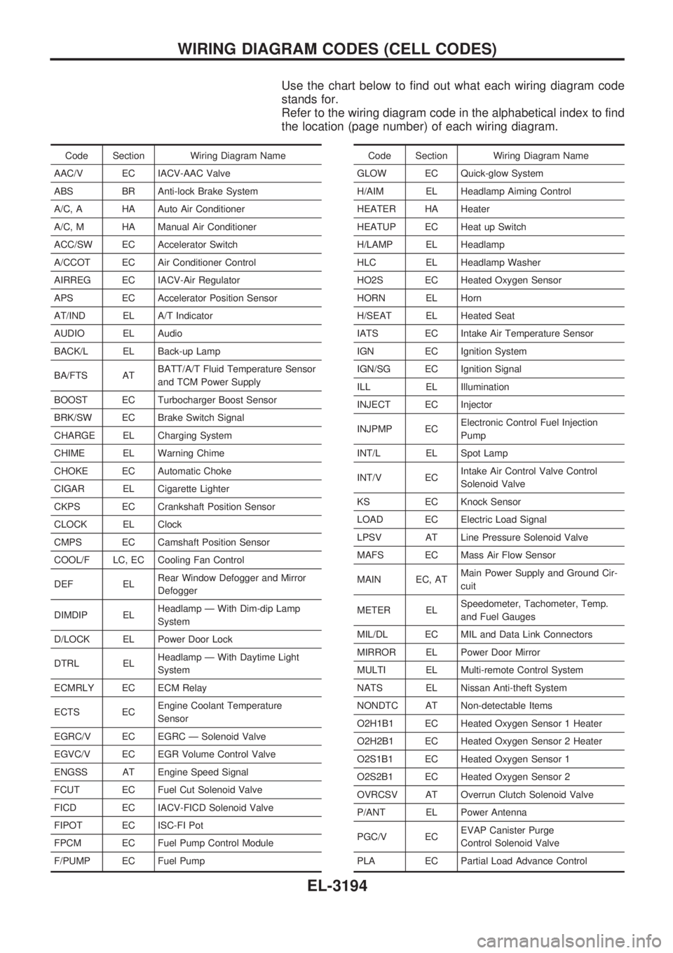
Use the chart below to find out what each wiring diagram code
stands for.
Refer to the wiring diagram code in the alphabetical index to find
the location (page number) of each wiring diagram.
Code Section Wiring Diagram Name
AAC/V EC IACV-AAC Valve
ABS BR Anti-lock Brake System
A/C, A HA Auto Air Conditioner
A/C, M HA Manual Air Conditioner
ACC/SW EC Accelerator Switch
A/CCOT EC Air Conditioner Control
AIRREG EC IACV-Air Regulator
APS EC Accelerator Position Sensor
AT/IND EL A/T Indicator
AUDIO EL Audio
BACK/L EL Back-up Lamp
BA/FTS ATBATT/A/T Fluid Temperature Sensor
and TCM Power Supply
BOOST EC Turbocharger Boost Sensor
BRK/SW EC Brake Switch Signal
CHARGE EL Charging System
CHIME EL Warning Chime
CHOKE EC Automatic Choke
CIGAR EL Cigarette Lighter
CKPS EC Crankshaft Position Sensor
CLOCK EL Clock
CMPS EC Camshaft Position Sensor
COOL/F LC, EC Cooling Fan Control
DEF ELRear Window Defogger and Mirror
Defogger
DIMDIP ELHeadlamp Ð With Dim-dip Lamp
System
D/LOCK EL Power Door Lock
DTRL ELHeadlamp Ð With Daytime Light
System
ECMRLY EC ECM Relay
ECTS ECEngine Coolant Temperature
Sensor
EGRC/V EC EGRC Ð Solenoid Valve
EGVC/V EC EGR Volume Control Valve
ENGSS AT Engine Speed Signal
FCUT EC Fuel Cut Solenoid Valve
FICD EC IACV-FICD Solenoid Valve
FIPOT EC ISC-FI Pot
FPCM EC Fuel Pump Control Module
F/PUMP EC Fuel PumpCode Section Wiring Diagram Name
GLOW EC Quick-glow System
H/AIM EL Headlamp Aiming Control
HEATER HA Heater
HEATUP EC Heat up Switch
H/LAMP EL Headlamp
HLC EL Headlamp Washer
HO2S EC Heated Oxygen Sensor
HORN EL Horn
H/SEAT EL Heated Seat
IATS EC Intake Air Temperature Sensor
IGN EC Ignition System
IGN/SG EC Ignition Signal
ILL EL Illumination
INJECT EC Injector
INJPMP ECElectronic Control Fuel Injection
Pump
INT/L EL Spot Lamp
INT/V ECIntake Air Control Valve Control
Solenoid Valve
KS EC Knock Sensor
LOAD EC Electric Load Signal
LPSV AT Line Pressure Solenoid Valve
MAFS EC Mass Air Flow Sensor
MAIN EC, ATMain Power Supply and Ground Cir-
cuit
METER ELSpeedometer, Tachometer, Temp.
and Fuel Gauges
MIL/DL EC MIL and Data Link Connectors
MIRROR EL Power Door Mirror
MULTI EL Multi-remote Control System
NATS EL Nissan Anti-theft System
NONDTC AT Non-detectable Items
O2H1B1 EC Heated Oxygen Sensor 1 Heater
O2H2B1 EC Heated Oxygen Sensor 2 Heater
O2S1B1 EC Heated Oxygen Sensor 1
O2S2B1 EC Heated Oxygen Sensor 2
OVRCSV AT Overrun Clutch Solenoid Valve
P/ANT EL Power Antenna
PGC/V ECEVAP Canister Purge
Control Solenoid Valve
PLA EC Partial Load Advance Control
WIRING DIAGRAM CODES (CELL CODES)
EL-3194