2001 NISSAN PICK-UP power steering fluid
[x] Cancel search: power steering fluidPage 445 of 1306

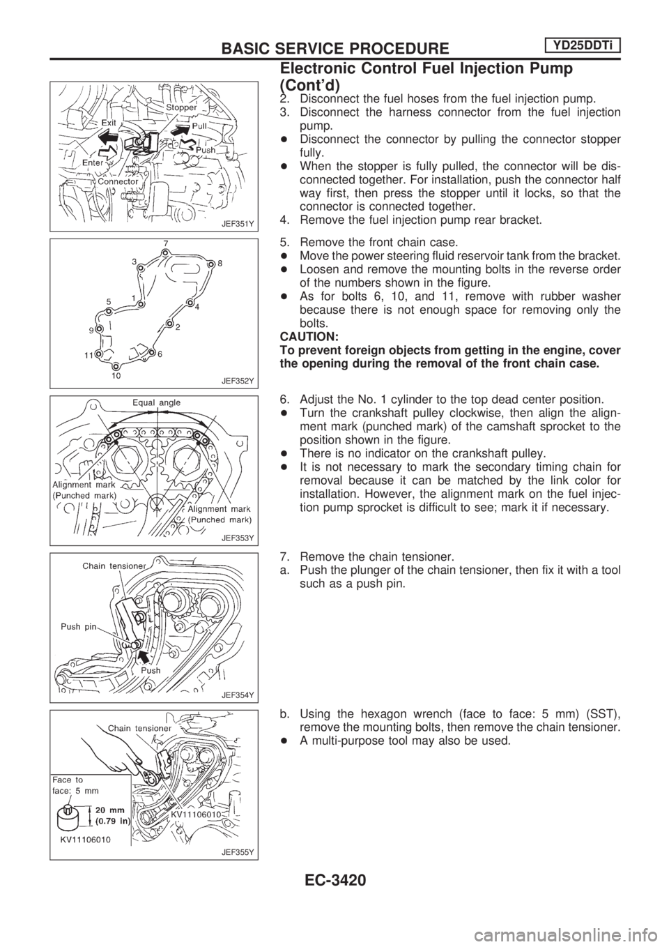
2. Disconnect the fuel hoses from the fuel injection pump.
3. Disconnect the harness connector from the fuel injection
pump.
+Disconnect the connector by pulling the connector stopper
fully.
+When the stopper is fully pulled, the connector will be dis-
connected together. For installation, push the connector half
way first, then press the stopper until it locks, so that the
connector is connected together.
4. Remove the fuel injection pump rear bracket.
5. Remove the front chain case.
+Move the power steering fluid reservoir tank from the bracket.
+Loosen and remove the mounting bolts in the reverse order
of the numbers shown in the figure.
+As for bolts 6, 10, and 11, remove with rubber washer
because there is not enough space for removing only the
bolts.
CAUTION:
To prevent foreign objects from getting in the engine, cover
the opening during the removal of the front chain case.
6. Adjust the No. 1 cylinder to the top dead center position.
+Turn the crankshaft pulley clockwise, then align the align-
ment mark (punched mark) of the camshaft sprocket to the
position shown in the figure.
+There is no indicator on the crankshaft pulley.
+It is not necessary to mark the secondary timing chain for
removal because it can be matched by the link color for
installation. However, the alignment mark on the fuel injec-
tion pump sprocket is difficult to see; mark it if necessary.
7. Remove the chain tensioner.
a. Push the plunger of the chain tensioner, then fix it with a tool
such as a push pin.
b. Using the hexagon wrench (face to face: 5 mm) (SST),
remove the mounting bolts, then remove the chain tensioner.
+A multi-purpose tool may also be used.
JEF351Y
JEF352Y
JEF353Y
JEF354Y
JEF355Y
BASIC SERVICE PROCEDUREYD25DDTi
Electronic Control Fuel Injection Pump
(Cont'd)
EC-3420
Page 899 of 1306

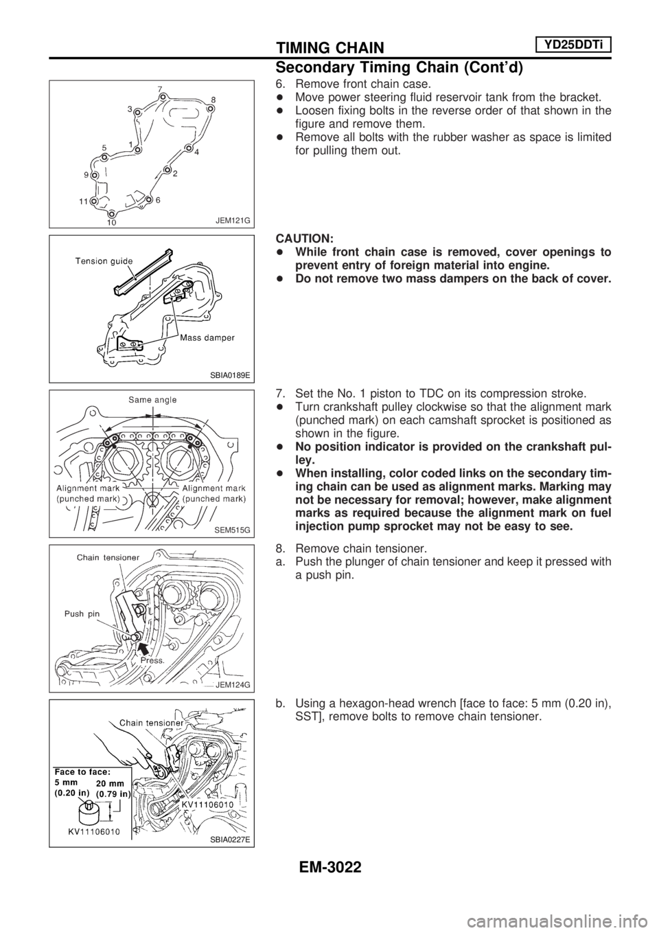
6. Remove front chain case.
+Move power steering fluid reservoir tank from the bracket.
+Loosen fixing bolts in the reverse order of that shown in the
figure and remove them.
+Remove all bolts with the rubber washer as space is limited
for pulling them out.
CAUTION:
+While front chain case is removed, cover openings to
prevent entry of foreign material into engine.
+Do not remove two mass dampers on the back of cover.
7. Set the No. 1 piston to TDC on its compression stroke.
+Turn crankshaft pulley clockwise so that the alignment mark
(punched mark) on each camshaft sprocket is positioned as
shown in the figure.
+No position indicator is provided on the crankshaft pul-
ley.
+When installing, color coded links on the secondary tim-
ing chain can be used as alignment marks. Marking may
not be necessary for removal; however, make alignment
marks as required because the alignment mark on fuel
injection pump sprocket may not be easy to see.
8. Remove chain tensioner.
a. Push the plunger of chain tensioner and keep it pressed with
a push pin.
b. Using a hexagon-head wrench [face to face: 5 mm (0.20 in),
SST], remove bolts to remove chain tensioner.
JEM121G
SBIA0189E
SEM515G
JEM124G
SBIA0227E
TIMING CHAINYD25DDTi
Secondary Timing Chain (Cont'd)
EM-3022
Page 1030 of 1306

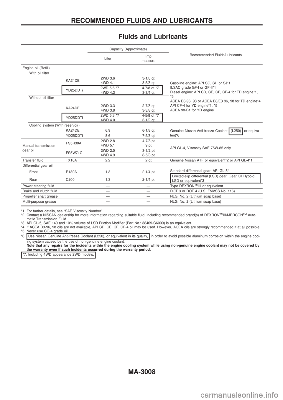
Fluids and Lubricants
Capacity (Approximate)
Recommended Fluids/Lubricants
LiterImp
measure
Engine oil (Refill)
With oil filter
Gasoline engine: API SG, SH or SJ*1
ILSAC grade GF-I or GF-II*1
Diesel engine: API CD, CE, CF, CF-4 for TD engine*1,
*5
ACEA B3-96, 98 or ACEA B3/E3 96, 98 for TD engine*4
API CF-4 for YD engine*1, *5
ACEA 98-B1 for YD engine KA24DE2WD 3.6
4WD 4.13-1/8 qt
3-5/8 qt
YD25DDTi2WD 5.6 *7
4WD 4.34-7/8 qt *7
3-3/4 qt
Without oil filter
KA24DE2WD 3.3
4WD 3.82-7/8 qt
3-3/8 qt
YD25DDTi2WD 5.3 *7
4WD 4.04-5/8 qt *7
3-1/2 qt
Cooling system (With reservoir)
KA24DE 6.9 6-1/8 qt
Genuine Nissan Anti-freeze Coolant (L250)
or equiva-
lent*6
YD25DDTi 8.6 7-5/8 qt
Manual transmission
gear oilFS5R30A2WD 2.8
4WD 5.14-7/8 pt
9pt
API GL-4, Viscosity SAE 75W-85 only
FS5W71C2WD 2.0
4WD 4.93-1/2 pt
8-5/8 pt
Transfer fluid TX10A 2.2 2 qt Genuine Nissan ATF or equivalent*2 or API GL-4*1
Differential gear oil
Front R180A 1.3 2-1/4 pt
Standard differential gear: API GL-5*1
Limited-slip differential (LSD) gear: Gear Oil Hypoid
LSD or equivalent*3 Rear C200 1.3 2-1/4 pt
Power steering fluid Ð Ð Type DEXRON
TMIII or equivalent
Brake and clutch fluid Ð Ð DOT 3 or DOT 4 (U.S. FMVSS No. 116)
Propeller shaft grease Ð Ð NLGI No. 2 (Lithium soap base)
Multi-purpose grease Ð Ð NLGI No. 2 (Lithium soap base)
*1: For further details, see ªSAE Viscosity Numberº.
*2: Contact a NISSAN dealership for more information regarding suitable fluid, including recommended brand(s) of DEXRONTMIII/MERCONTMAuto-
matic Transmission Fluid.
*3: API GL-5, SAE 140 and 10% volume of LSD Friction Modifier (Part No.: 38469-C6000) is an equivalent.
*4: If ACEA B3-96, 98 oils are not available, API CD, CE, CF, CF-4 oil may be used. However, ACEA oils are strongly recommended if at all possible.
*5: Never use CG-4 grade oil.
*6: Use Nissan Genuine Anti-freeze Coolant (L250), or equivalent in its quality,
in order to avoid possible aluminum corrosion within the engine cool-
ing system caused by the use of non-genuine engine coolant.
Note that any repairs for the incidents within the engine cooling system while using non-genuine engine coolant may not be covered by
the warranty even if such incidents occurred during the warranty period.
*7: Including 4WD appearance 2WD models.
RECOMMENDED FLUIDS AND LUBRICANTS
MA-3008
Page 1034 of 1306

+When checking belt deflection immediately after
installation, first adjust it to the specified value. Then,
after turning crankshaft two turns or more, re-adjust it to
the specified value to avoid variation in deflection
between pulleys.
+Make sure the belts are fully fitted into the pulley
grooves during installation.
+Handle with care to avoid smearing the belts with oil or
cooling water etc.
+Do not twist or bend the belts with strong force.
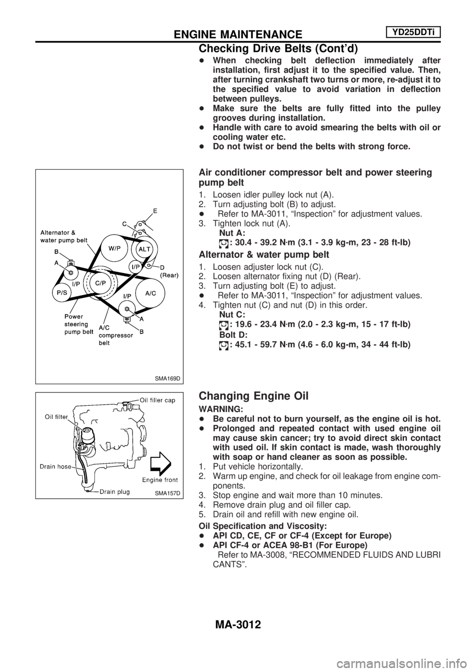
Air conditioner compressor belt and power steering
pump belt
1. Loosen idler pulley lock nut (A).
2. Turn adjusting bolt (B) to adjust.
+Refer to MA-3011, ªInspectionº for adjustment values.
3. Tighten lock nut (A).
Nut A:
: 30.4 - 39.2 Nzm (3.1 - 3.9 kg-m, 23 - 28 ft-lb)
Alternator & water pump belt
1. Loosen adjuster lock nut (C).
2. Loosen alternator fixing nut (D) (Rear).
3. Turn adjusting bolt (E) to adjust.
+Refer to MA-3011, ªInspectionº for adjustment values.
4. Tighten nut (C) and nut (D) in this order.
Nut C:
: 19.6 - 23.4 Nzm (2.0 - 2.3 kg-m, 15 - 17 ft-lb)
Bolt D:
: 45.1 - 59.7 Nzm (4.6 - 6.0 kg-m, 34 - 44 ft-lb)
Changing Engine Oil
WARNING:
+Be careful not to burn yourself, as the engine oil is hot.
+Prolonged and repeated contact with used engine oil
may cause skin cancer; try to avoid direct skin contact
with used oil. If skin contact is made, wash thoroughly
with soap or hand cleaner as soon as possible.
1. Put vehicle horizontally.
2. Warm up engine, and check for oil leakage from engine com-
ponents.
3. Stop engine and wait more than 10 minutes.
4. Remove drain plug and oil filler cap.
5. Drain oil and refill with new engine oil.
Oil Specification and Viscosity:
+API CD, CE, CF or CF-4 (Except for Europe)
+API CF-4 or ACEA 98-B1 (For Europe)
Refer to MA-3008, ªRECOMMENDED FLUIDS AND LUBRI
CANTSº.
SMA169D
SMA157D
ENGINE MAINTENANCEYD25DDTi
Checking Drive Belts (Cont'd)
MA-3012