2001 NISSAN PICK-UP water pump
[x] Cancel search: water pumpPage 30 of 1306
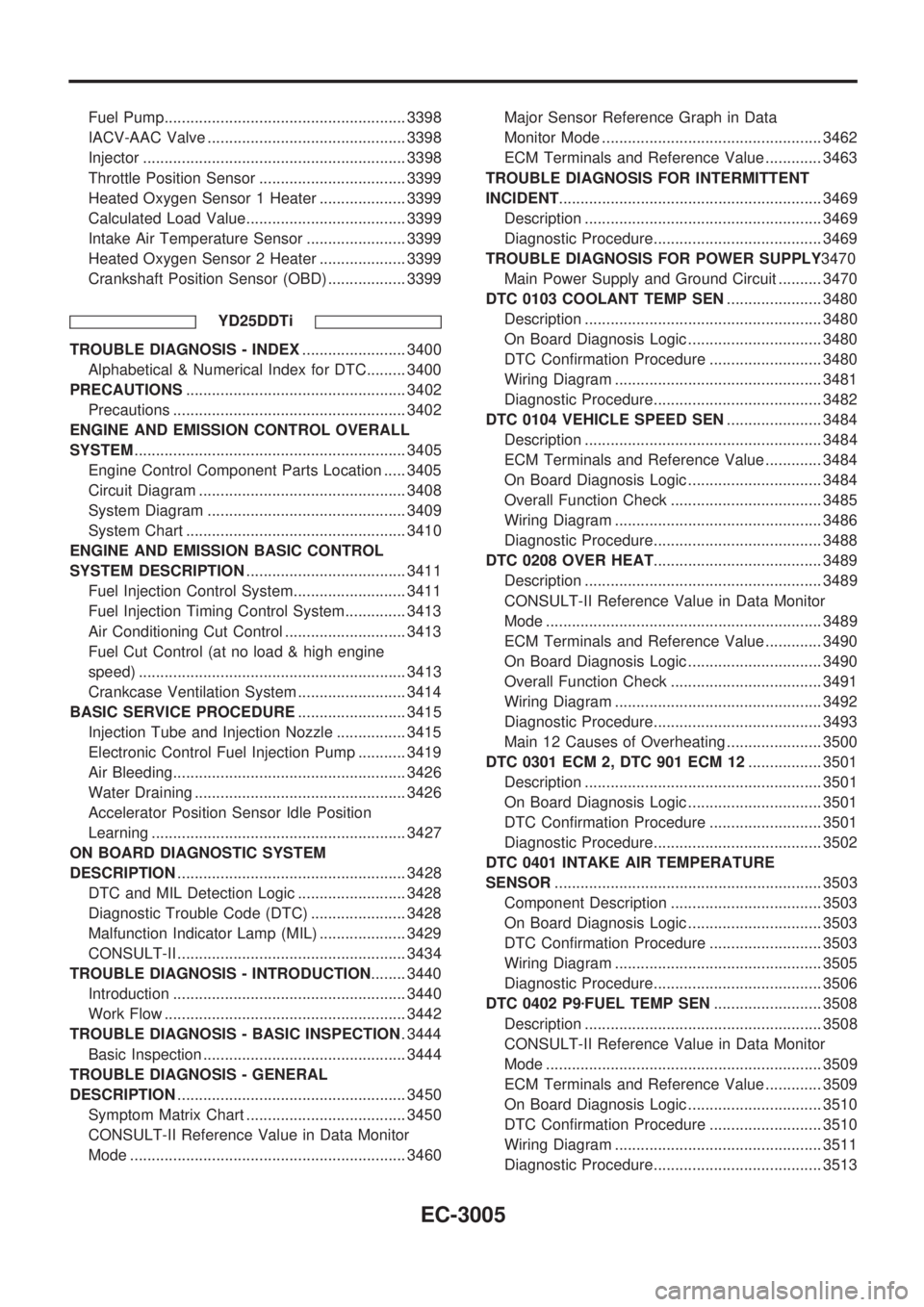
Fuel Pump........................................................ 3398
IACV-AAC Valve .............................................. 3398
Injector ............................................................. 3398
Throttle Position Sensor .................................. 3399
Heated Oxygen Sensor 1 Heater .................... 3399
Calculated Load Value..................................... 3399
Intake Air Temperature Sensor ....................... 3399
Heated Oxygen Sensor 2 Heater .................... 3399
Crankshaft Position Sensor (OBD) .................. 3399
YD25DDTi
TROUBLE DIAGNOSIS - INDEX........................ 3400
Alphabetical & Numerical Index for DTC......... 3400
PRECAUTIONS................................................... 3402
Precautions ...................................................... 3402
ENGINE AND EMISSION CONTROL OVERALL
SYSTEM............................................................... 3405
Engine Control Component Parts Location ..... 3405
Circuit Diagram ................................................ 3408
System Diagram .............................................. 3409
System Chart ................................................... 3410
ENGINE AND EMISSION BASIC CONTROL
SYSTEM DESCRIPTION..................................... 3411
Fuel Injection Control System.......................... 3411
Fuel Injection Timing Control System.............. 3413
Air Conditioning Cut Control ............................ 3413
Fuel Cut Control (at no load & high engine
speed) .............................................................. 3413
Crankcase Ventilation System ......................... 3414
BASIC SERVICE PROCEDURE......................... 3415
Injection Tube and Injection Nozzle ................ 3415
Electronic Control Fuel Injection Pump ........... 3419
Air Bleeding...................................................... 3426
Water Draining ................................................. 3426
Accelerator Position Sensor Idle Position
Learning ........................................................... 3427
ON BOARD DIAGNOSTIC SYSTEM
DESCRIPTION..................................................... 3428
DTC and MIL Detection Logic ......................... 3428
Diagnostic Trouble Code (DTC) ...................... 3428
Malfunction Indicator Lamp (MIL) .................... 3429
CONSULT-II ..................................................... 3434
TROUBLE DIAGNOSIS - INTRODUCTION........ 3440
Introduction ...................................................... 3440
Work Flow ........................................................ 3442
TROUBLE DIAGNOSIS - BASIC INSPECTION. 3444
Basic Inspection ............................................... 3444
TROUBLE DIAGNOSIS - GENERAL
DESCRIPTION..................................................... 3450
Symptom Matrix Chart ..................................... 3450
CONSULT-II Reference Value in Data Monitor
Mode ................................................................ 3460Major Sensor Reference Graph in Data
Monitor Mode ................................................... 3462
ECM Terminals and Reference Value ............. 3463
TROUBLE DIAGNOSIS FOR INTERMITTENT
INCIDENT............................................................. 3469
Description ....................................................... 3469
Diagnostic Procedure....................................... 3469
TROUBLE DIAGNOSIS FOR POWER SUPPLY3470
Main Power Supply and Ground Circuit .......... 3470
DTC 0103 COOLANT TEMP SEN...................... 3480
Description ....................................................... 3480
On Board Diagnosis Logic ............................... 3480
DTC Confirmation Procedure .......................... 3480
Wiring Diagram ................................................ 3481
Diagnostic Procedure....................................... 3482
DTC 0104 VEHICLE SPEED SEN...................... 3484
Description ....................................................... 3484
ECM Terminals and Reference Value ............. 3484
On Board Diagnosis Logic ............................... 3484
Overall Function Check ................................... 3485
Wiring Diagram ................................................ 3486
Diagnostic Procedure....................................... 3488
DTC 0208 OVER HEAT....................................... 3489
Description ....................................................... 3489
CONSULT-II Reference Value in Data Monitor
Mode ................................................................ 3489
ECM Terminals and Reference Value ............. 3490
On Board Diagnosis Logic ............................... 3490
Overall Function Check ................................... 3491
Wiring Diagram ................................................ 3492
Diagnostic Procedure....................................... 3493
Main 12 Causes of Overheating ...................... 3500
DTC 0301 ECM 2, DTC 901 ECM 12................. 3501
Description ....................................................... 3501
On Board Diagnosis Logic ............................... 3501
DTC Confirmation Procedure .......................... 3501
Diagnostic Procedure....................................... 3502
DTC 0401 INTAKE AIR TEMPERATURE
SENSOR.............................................................. 3503
Component Description ................................... 3503
On Board Diagnosis Logic ............................... 3503
DTC Confirmation Procedure .......................... 3503
Wiring Diagram ................................................ 3505
Diagnostic Procedure....................................... 3506
DTC 0402 P9zFUEL TEMP SEN......................... 3508
Description ....................................................... 3508
CONSULT-II Reference Value in Data Monitor
Mode ................................................................ 3509
ECM Terminals and Reference Value ............. 3509
On Board Diagnosis Logic ............................... 3510
DTC Confirmation Procedure .......................... 3510
Wiring Diagram ................................................ 3511
Diagnostic Procedure....................................... 3513
EC-3005
Page 127 of 1306
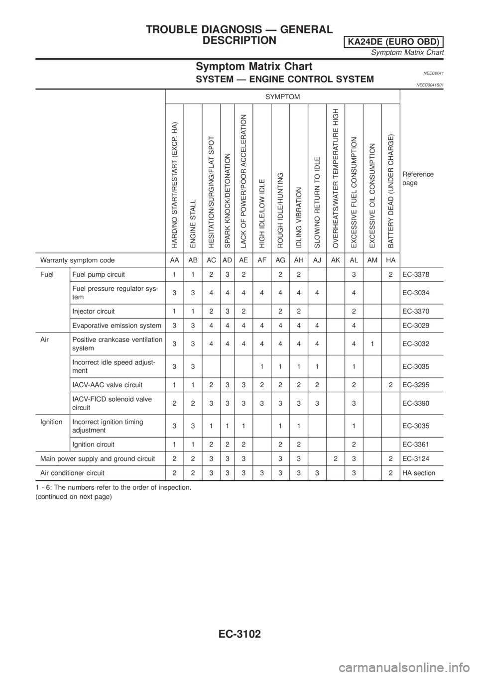
Symptom Matrix ChartNEEC0041SYSTEM Ð ENGINE CONTROL SYSTEMNEEC0041S01
SYMPTOM
Reference
page
HARD/NO START/RESTART (EXCP. HA)
ENGINE STALL
HESITATION/SURGING/FLAT SPOT
SPARK KNOCK/DETONATION
LACK OF POWER/POOR ACCELERATION
HIGH IDLE/LOW IDLE
ROUGH IDLE/HUNTING
IDLING VIBRATION
SLOW/NO RETURN TO IDLE
OVERHEATS/WATER TEMPERATURE HIGH
EXCESSIVE FUEL CONSUMPTION
EXCESSIVE OIL CONSUMPTION
BATTERY DEAD (UNDER CHARGE)
Warranty symptom code AA AB AC AD AE AF AG AH AJ AK AL AM HA
Fuel Fuel pump circuit 1 1 2 3 2 2 2 3 2 EC-3378
Fuel pressure regulator sys-
tem334444444 4EC-3034
Injector circuit 1 1 2 3 2 2 2 2 EC-3370
Evaporative emission system 3 3 4 444444 4EC-3029
Air Positive crankcase ventilation
system334444444 41EC-3032
Incorrect idle speed adjust-
ment33 1111 1EC-3035
IACV-AAC valve circuit 1 1 2 332222 2 2EC-3295
IACV-FICD solenoid valve
circuit223333333 3EC-3390
Ignition Incorrect ignition timing
adjustment3 3 1 1 1 1 1 1 EC-3035
Ignition circuit 1 1 2 2 2 2 2 2 EC-3361
Main power supply and ground circuit 2 2 3 3 3 3 3 2 3 2 EC-3124
Air conditioner circuit 2 2 3 333333 3 2HAsection
1 - 6: The numbers refer to the order of inspection.
(continued on next page)
TROUBLE DIAGNOSIS Ð GENERAL
DESCRIPTION
KA24DE (EURO OBD)
Symptom Matrix Chart
EC-3102
Page 130 of 1306
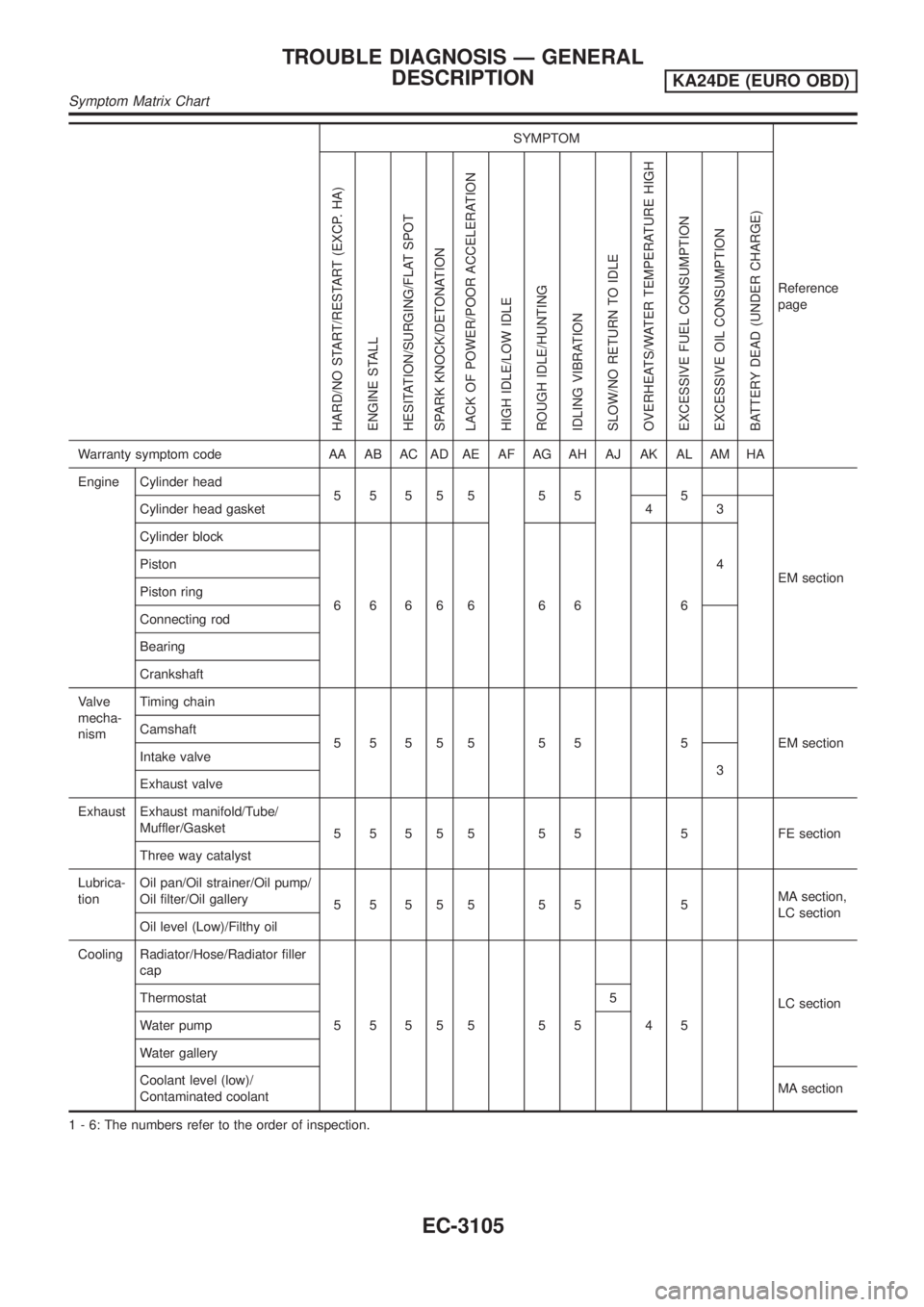
SYMPTOM
Reference
page
HARD/NO START/RESTART (EXCP. HA)
ENGINE STALL
HESITATION/SURGING/FLAT SPOT
SPARK KNOCK/DETONATION
LACK OF POWER/POOR ACCELERATION
HIGH IDLE/LOW IDLE
ROUGH IDLE/HUNTING
IDLING VIBRATION
SLOW/NO RETURN TO IDLE
OVERHEATS/WATER TEMPERATURE HIGH
EXCESSIVE FUEL CONSUMPTION
EXCESSIVE OIL CONSUMPTION
BATTERY DEAD (UNDER CHARGE)
Warranty symptom code AA AB AC AD AE AF AG AH AJ AK AL AM HA
Engine Cylinder head
55555 55 5
EM section Cylinder head gasket 4 3
Cylinder block
66666 66 64 Piston
Piston ring
Connecting rod
Bearing
Crankshaft
Valve
mecha-
nismTiming chain
5 5 5 5 5 5 5 5 EM section Camshaft
Intake valve
3
Exhaust valve
Exhaust Exhaust manifold/Tube/
Muffler/Gasket
5 5 5 5 5 5 5 5 FE section
Three way catalyst
Lubrica-
tionOil pan/Oil strainer/Oil pump/
Oil filter/Oil gallery
55555 55 5MA section,
LC section
Oil level (Low)/Filthy oil
Cooling Radiator/Hose/Radiator filler
cap
55555 55 45LC section Thermostat 5
Water pump
Water gallery
Coolant level (low)/
Contaminated coolantMA section
1 - 6: The numbers refer to the order of inspection.
TROUBLE DIAGNOSIS Ð GENERAL
DESCRIPTION
KA24DE (EURO OBD)
Symptom Matrix Chart
EC-3105
Page 369 of 1306
On Board Diagnosis LogicNEEC1534If the cooling fan or another component in the cooling system malfunctions, engine coolant temperature will
rise.
When the engine coolant temperature reaches an abnormally high temperature condition, a malfunction is
indicated.
DTC No. Malfunction is detected when ...Check Items
(Possible Cause)
P1217
1217+Engine coolant temperature reaches an abnormally high
temperature.+Cooling fan (crankshaft driven)
Radiator hose
+Radiator
+Radiator cap
+Water pump
+Thermostat
+Engine coolant temperature sensor
For more information, refer to ªMAIN 11 CAUSES
OF OVERHEATINGº, EC-3348.
CAUTION:
When a malfunction is indicated, be sure to replace the coolant. Refer to MA section, ªChanging Engine
Coolantº. Also, replace the engine oil.
1) Fill radiator with coolant up to specified level with a filling speed of 2 liters per minute. Be sure
to use coolant with the proper mixture ratio. Refer to MA section, ªAnti-freeze Coolant Mixture
Ratioº.
2) After refilling coolant, run engine to ensure that no water-flow noise is emitted.
SEF621W
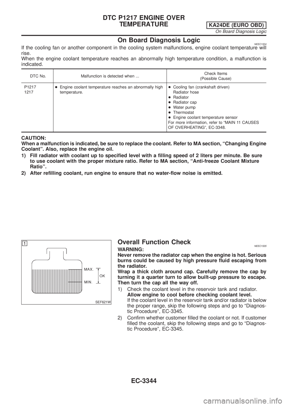
Overall Function CheckNEEC1535WARNING:
Never remove the radiator cap when the engine is hot. Serious
burns could be caused by high pressure fluid escaping from
the radiator.
Wrap a thick cloth around cap. Carefully remove the cap by
turning it a quarter turn to allow built-up pressure to escape.
Then turn the cap all the way off.
1) Check the coolant level in the reservoir tank and radiator.
Allow engine to cool before checking coolant level.
If the coolant level in the reservoir tank and/or radiator is below
the proper range, skip the following steps and go to ªDiagnos-
tic Procedureº, EC-3345.
2) Confirm whether customer filled the coolant or not. If customer
filled the coolant, skip the following steps and go to ªDiagnos-
tic Procedureº, EC-3345.
DTC P1217 ENGINE OVER
TEMPERATURE
KA24DE (EURO OBD)
On Board Diagnosis Logic
EC-3344
Page 370 of 1306
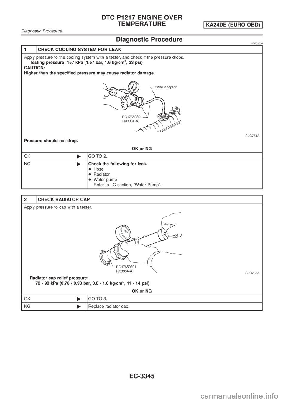
Diagnostic ProcedureNEEC1536
1 CHECK COOLING SYSTEM FOR LEAK
Apply pressure to the cooling system with a tester, and check if the pressure drops.
Testing pressure: 157 kPa (1.57 bar, 1.6 kg/cm2, 23 psi)
CAUTION:
Higher than the specified pressure may cause radiator damage.
SLC754A
Pressure should not drop.
OK or NG
OK©GO TO 2.
NG©Check the following for leak.
+Hose
+Radiator
+Water pump
Refer to LC section, ªWater Pumpº.
2 CHECK RADIATOR CAP
Apply pressure to cap with a tester.
SLC755A
Radiator cap relief pressure:
78 - 98 kPa (0.78 - 0.98 bar, 0.8 - 1.0 kg/cm2, 11 - 14 psi)
OK or NG
OK©GO TO 3.
NG©Replace radiator cap.
DTC P1217 ENGINE OVER
TEMPERATURE
KA24DE (EURO OBD)
Diagnostic Procedure
EC-3345
Page 451 of 1306
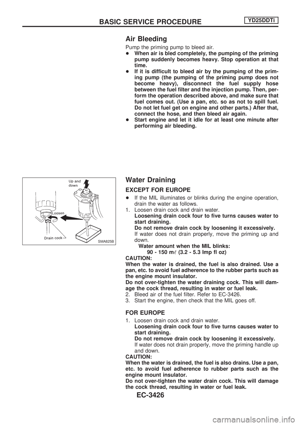
Air Bleeding
Pump the priming pump to bleed air.
+When air is bled completely, the pumping of the priming
pump suddenly becomes heavy. Stop operation at that
time.
+If it is difficult to bleed air by the pumping of the prim-
ing pump (the pumping of the priming pump does not
become heavy), disconnect the fuel supply hose
between the fuel filter and the injection pump. Then, per-
form the operation described above, and make sure that
fuel comes out. (Use a pan, etc. so as not to spill fuel.
Do not let fuel get on engine and other parts.) After that,
connect the hose, and then bleed air again.
+Start engine and let it idle for at least one minute after
performing air bleeding.
Water Draining
EXCEPT FOR EUROPE
+If the MIL illuminates or blinks during the engine operation,
drain the water as follows.
1. Loosen drain cock and drain water.
Loosening drain cock four to five turns causes water to
start draining.
Do not remove drain cock by loosening it excessively.
If water does not drain properly, move the priming up and
down.
Water amount when the MIL blinks:
90 - 150 m!(3.2 - 5.3 Imp fl oz)
CAUTION:
When the water is drained, the fuel is also drained. Use a
pan, etc. to avoid fuel adherence to the rubber parts such as
the engine mount insulator.
Do not over-tighten the water draining cock. This will dam-
age the cock thread, resulting in water or fuel leak.
2. Bleed air of the fuel filter. Refer to EC-3426.
3. Start the engine, then check that the MIL goes off.
FOR EUROPE
1. Loosen drain cock and drain water.
Loosening drain cock four to five turns causes water to
start draining.
Do not remove drain cock by loosening it excessively.
If water does not drain properly, move the priming handle up
and down.
CAUTION:
When the water is drained, the fuel is also drains. Use a pan,
etc. to avoid fuel adherence to rubber parts such as the
engine mount insulator.
Do not over-tighten the water drain cock. This will damage
the cock thread, resulting in water or fuel leak.
SMA825B
BASIC SERVICE PROCEDUREYD25DDTi
EC-3426
Page 515 of 1306
ECM Terminals and Reference Value
Specification data are reference values and are measured between each terminal and ground.
CAUTION:
Do not use ECM ground terminals when measuring input/output voltage. Doing so may damage the
ECM's transistor. Use a ground other than ECM terminals, such as the ground.
TER-
MINAL
NO.WIRE
COLORITEM CONDITION DATA (DC Voltage)
14 G/B Cooling fan relayEngine is running.
Cooling fan is not operatingBATTERY VOLTAGE
(11 - 14V)
Engine is running.
Cooling fan is operatingApproximately 0.1V
On Board Diagnosis Logic
This diagnosis continuously monitors the engine coolant temperature.
If the cooling fan or another component in the cooling system malfunctions, engine coolant temperature will
rise.
When the engine coolant temperature reaches an abnormally high temperature condition, a malfunction is
indicated.
Malfunction is detected when ... Check Items (Possible Cause)
+Cooling fan does not operate properly (Overheat).
+Cooling fan system does not operate properly (Overheat).
+Engine coolant was not added to the system using the proper
filling method.+Harness or connectors
(The cooling fan circuit is open or shorted.)
+Cooling fan
+Radiator hose
+Radiator
+Radiator cap
+Water pump
+Thermostat
+Fan belt
+Engine coolant temperature sensor
For more information, refer to ªMAIN 12 CAUSES OF
OVERHEATINGº, EC-3501.
CAUTION:
When a malfunction is indicated, be sure to replace the coolant following the procedure in the MA
section (ªChanging Engine Coolantº, ªENGINE MAINTENANCEº). Also, replace the engine oil.
1) Fill radiator with coolant up to specified level with a filling speed of 2 liters per minute. Be sure
to use coolant with the proper mixture ratio. Refer to MA section (ªAnti-freeze Coolant Mixture
Ratioº, ªRECOMMENDED LUBRICANTS AND FLUIDSº).
2) After refilling coolant, run engine to ensure that no water-flow noise is emitted.
DTC 0208 OVER HEATYD25DDTi
EC-3490
Page 523 of 1306
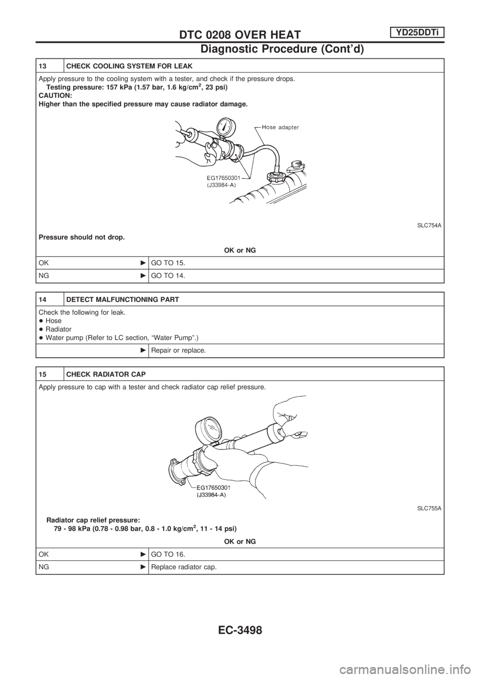
13 CHECK COOLING SYSTEM FOR LEAK
Apply pressure to the cooling system with a tester, and check if the pressure drops.
Testing pressure: 157 kPa (1.57 bar, 1.6 kg/cm
2, 23 psi)
CAUTION:
Higher than the specified pressure may cause radiator damage.
SLC754A
Pressure should not drop.
OK or NG
OKcGO TO 15.
NGcGO TO 14.
14 DETECT MALFUNCTIONING PART
Check the following for leak.
+Hose
+Radiator
+Water pump (Refer to LC section, ªWater Pumpº.)
cRepair or replace.
15 CHECK RADIATOR CAP
Apply pressure to cap with a tester and check radiator cap relief pressure.
SLC755A
Radiator cap relief pressure:
79 - 98 kPa (0.78 - 0.98 bar, 0.8 - 1.0 kg/cm2, 11 - 14 psi)
OK or NG
OKcGO TO 16.
NGcReplace radiator cap.
DTC 0208 OVER HEATYD25DDTi
Diagnostic Procedure (Cont'd)
EC-3498