2001 NISSAN PICK-UP heater
[x] Cancel search: heaterPage 1 of 1306

GENERAL INFORMATIONGI
MAINTENANCEMA
ENGINE MECHANICALEM
ENGINE LUBRICATION &
COOLING SYSTEMSLC
ENGINE CONTROL SYSTEMEC
ACCELERATOR CONTROL, FUEL &
EXHAUST SYSTEMSFE
CLUTCHCL
MANUAL TRANSAXLEMT
TRANSFERTF
PROPELLER SHAFT &
DIFFERENTIAL CARRIERPD
FRONT AXLE & FRONT SUSPENSIONFA
REAR AXLE & REAR SUSPENSIONRA
BRAKE SYSTEMBR
STEERING SYSTEMST
RESTRAINT SYSTEMRS
BODY & TRIMBT
HEATER & AIR CONDITIONERHA
ELECTRICAL SYSTEMEL
ALPHABETICAL INDEXIDX
PICKUP
MODEL D22 SERIES
FOREWORD
This supplement contains informa-
tion concerning necessary service
procedures and relevant data for the
model D22 series.
All information, illustrations and spe-
ci®cations contained in this supple-
ment are based on the latest product
information available at the time of
publication. If your NISSAN model
differs from the speci®cations contain-
ed in this supplement, consult your
NISSAN distributor for information.
The right is reserved to make chan-
ges in speci®cations and methods at
any time without notice.
Edition: November 2001
Printing: November 2001 (01)
Publication No.: SM1E-D22CE0E
NISSAN EUROPE S.A.S.
2001 NISSAN EUROPE S.A.S. Printed in the Netherlands
Not to be reproduced in whole or in part without the prior written permission of Nissan Europe S.A.S., Paris, France.
QUICK REFERENCE INDEX
Page 27 of 1306

ECM Terminals and Reference Value ............. 3110
Trouble Diagnosis - Specification Value......... 3119
Description ....................................................... 3119
Testing Condition ............................................. 3119
Inspection Procedure ....................................... 3119
Diagnostic Procedure....................................... 3120
Trouble Diagnosis for Intermittent Incident.... 3123
Description ....................................................... 3123
Diagnostic Procedure....................................... 3123
Trouble Diagnosis for Power Supply............... 3124
Main Power Supply and Ground Circuit .......... 3124
DTC P0031, P0032 HO2S1 Heater..................... 3133
Description ....................................................... 3133
CONSULT-II Reference Value in Data Monitor
Mode ................................................................ 3133
ECM Terminals and Reference Value ............. 3133
On Board Diagnosis Logic ............................... 3133
DTC Confirmation Procedure .......................... 3134
Wiring Diagram ................................................ 3135
Diagnostic Procedure....................................... 3136
DTC P0037, P0038 HO2S2 Heater..................... 3138
Description ....................................................... 3138
CONSULT-II Reference Value in Data Monitor
Mode ................................................................ 3138
ECM Terminals and Reference Value ............. 3138
On Board Diagnosis Logic ............................... 3138
DTC Confirmation Procedure .......................... 3139
Wiring Diagram ................................................ 3140
Diagnostic Procedure....................................... 3141
DTC P0101 MAF Sensor.................................... 3143
Component Description ................................... 3143
CONSULT-II Reference Value in Data Monitor
Mode ................................................................ 3143
ECM Terminals and Reference Value ............. 3143
On Board Diagnosis Logic ............................... 3143
DTC Confirmation Procedure .......................... 3144
Overall Function Check ................................... 3145
Wiring Diagram ................................................ 3146
Diagnostic Procedure....................................... 3147
DTC P0102, P0103 MAF Sensor........................ 3151
Component Description ................................... 3151
CONSULT-II Reference Value in Data Monitor
Mode ................................................................ 3151
ECM Terminals and Reference Value ............. 3151
On Board Diagnosis Logic ............................... 3151
DTC Confirmation Procedure .......................... 3152
Wiring Diagram ................................................ 3154
Diagnostic Procedure....................................... 3155
DTC P0112, P0113 IAT Sensor.......................... 3160
Component Description ................................... 3160
ECM Terminals and Reference Value ............. 3160
On Board Diagnosis Logic ............................... 3160
DTC Confirmation Procedure .......................... 3161
Wiring Diagram ................................................ 3162Diagnostic Procedure....................................... 3163
DTC P0117, P0118 ECT Sensor........................ 3165
Component Description ................................... 3165
CONSULT-II Reference Value in Data Monitor
Mode ................................................................ 3165
ECM Terminals and Reference Value ............. 3165
On Board Diagnosis Logic ............................... 3166
DTC Confirmation Procedure .......................... 3166
Wiring Diagram ................................................ 3167
Diagnostic Procedure....................................... 3168
DTC P0121 TP Sensor....................................... 3170
Component Description ................................... 3170
CONSULT-II Reference Value in Data Monitor
Mode ................................................................ 3170
ECM Terminals and Reference Value ............. 3171
On Board Diagnosis Logic ............................... 3171
DTC Confirmation Procedure .......................... 3172
Wiring Diagram ................................................ 3174
Diagnostic Procedure....................................... 3175
DTC P0122, P0123 TP Sensor........................... 3182
Component Description ................................... 3182
CONSULT-II Reference Value in Data Monitor
Mode ................................................................ 3182
ECM Terminals and Reference Value ............. 3183
On Board Diagnosis Logic ............................... 3183
DTC Confirmation Procedure .......................... 3184
Wiring Diagram ................................................ 3185
Diagnostic Procedure....................................... 3186
DTC P0127 IAT Sensor...................................... 3193
Component Description ................................... 3193
ECM Terminals and Reference Value ............. 3193
On Board Diagnosis Logic ............................... 3193
DTC Confirmation Procedure .......................... 3194
Diagnostic Procedure....................................... 3195
DTC P0132 HO2S1.............................................. 3196
Component Description ................................... 3196
CONSULT-II Reference Value in Data Monitor
Mode ................................................................ 3196
ECM Terminals and Reference Value ............. 3196
On Board Diagnosis Logic ............................... 3197
DTC Confirmation Procedure .......................... 3197
Wiring Diagram ................................................ 3198
Diagnostic Procedure....................................... 3199
DTC P0133 HO2S1.............................................. 3202
Component Description ................................... 3202
CONSULT-II Reference Value in Data Monitor
Mode ................................................................ 3202
ECM Terminals and Reference Value ............. 3202
On Board Diagnosis Logic ............................... 3203
DTC Confirmation Procedure .......................... 3203
Overall Function Check ................................... 3204
Wiring Diagram ................................................ 3205
Diagnostic Procedure....................................... 3206
DTC P0134 HO2S1.............................................. 3213
BR-3002
Page 30 of 1306
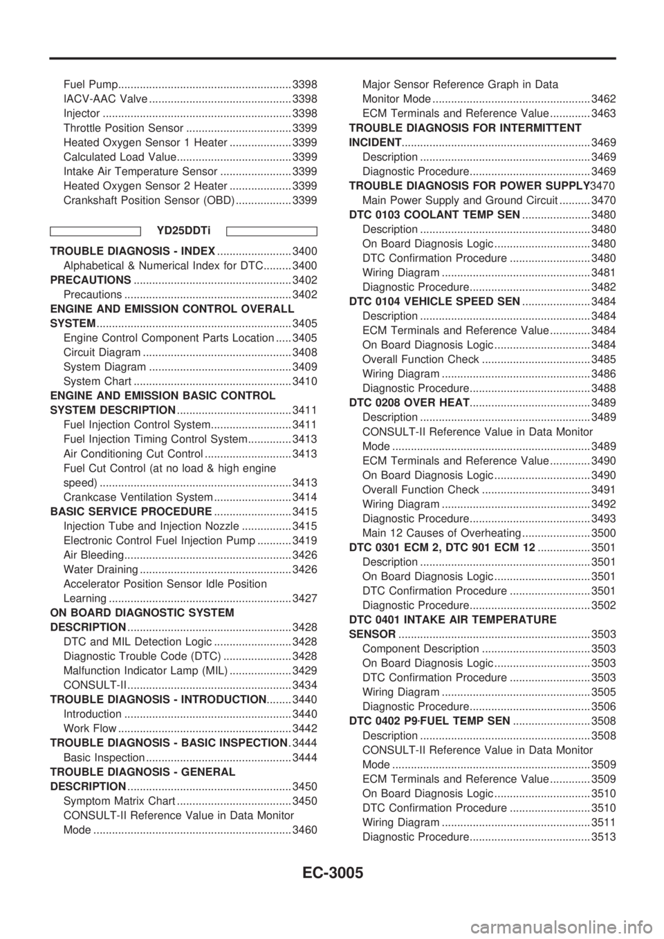
Fuel Pump........................................................ 3398
IACV-AAC Valve .............................................. 3398
Injector ............................................................. 3398
Throttle Position Sensor .................................. 3399
Heated Oxygen Sensor 1 Heater .................... 3399
Calculated Load Value..................................... 3399
Intake Air Temperature Sensor ....................... 3399
Heated Oxygen Sensor 2 Heater .................... 3399
Crankshaft Position Sensor (OBD) .................. 3399
YD25DDTi
TROUBLE DIAGNOSIS - INDEX........................ 3400
Alphabetical & Numerical Index for DTC......... 3400
PRECAUTIONS................................................... 3402
Precautions ...................................................... 3402
ENGINE AND EMISSION CONTROL OVERALL
SYSTEM............................................................... 3405
Engine Control Component Parts Location ..... 3405
Circuit Diagram ................................................ 3408
System Diagram .............................................. 3409
System Chart ................................................... 3410
ENGINE AND EMISSION BASIC CONTROL
SYSTEM DESCRIPTION..................................... 3411
Fuel Injection Control System.......................... 3411
Fuel Injection Timing Control System.............. 3413
Air Conditioning Cut Control ............................ 3413
Fuel Cut Control (at no load & high engine
speed) .............................................................. 3413
Crankcase Ventilation System ......................... 3414
BASIC SERVICE PROCEDURE......................... 3415
Injection Tube and Injection Nozzle ................ 3415
Electronic Control Fuel Injection Pump ........... 3419
Air Bleeding...................................................... 3426
Water Draining ................................................. 3426
Accelerator Position Sensor Idle Position
Learning ........................................................... 3427
ON BOARD DIAGNOSTIC SYSTEM
DESCRIPTION..................................................... 3428
DTC and MIL Detection Logic ......................... 3428
Diagnostic Trouble Code (DTC) ...................... 3428
Malfunction Indicator Lamp (MIL) .................... 3429
CONSULT-II ..................................................... 3434
TROUBLE DIAGNOSIS - INTRODUCTION........ 3440
Introduction ...................................................... 3440
Work Flow ........................................................ 3442
TROUBLE DIAGNOSIS - BASIC INSPECTION. 3444
Basic Inspection ............................................... 3444
TROUBLE DIAGNOSIS - GENERAL
DESCRIPTION..................................................... 3450
Symptom Matrix Chart ..................................... 3450
CONSULT-II Reference Value in Data Monitor
Mode ................................................................ 3460Major Sensor Reference Graph in Data
Monitor Mode ................................................... 3462
ECM Terminals and Reference Value ............. 3463
TROUBLE DIAGNOSIS FOR INTERMITTENT
INCIDENT............................................................. 3469
Description ....................................................... 3469
Diagnostic Procedure....................................... 3469
TROUBLE DIAGNOSIS FOR POWER SUPPLY3470
Main Power Supply and Ground Circuit .......... 3470
DTC 0103 COOLANT TEMP SEN...................... 3480
Description ....................................................... 3480
On Board Diagnosis Logic ............................... 3480
DTC Confirmation Procedure .......................... 3480
Wiring Diagram ................................................ 3481
Diagnostic Procedure....................................... 3482
DTC 0104 VEHICLE SPEED SEN...................... 3484
Description ....................................................... 3484
ECM Terminals and Reference Value ............. 3484
On Board Diagnosis Logic ............................... 3484
Overall Function Check ................................... 3485
Wiring Diagram ................................................ 3486
Diagnostic Procedure....................................... 3488
DTC 0208 OVER HEAT....................................... 3489
Description ....................................................... 3489
CONSULT-II Reference Value in Data Monitor
Mode ................................................................ 3489
ECM Terminals and Reference Value ............. 3490
On Board Diagnosis Logic ............................... 3490
Overall Function Check ................................... 3491
Wiring Diagram ................................................ 3492
Diagnostic Procedure....................................... 3493
Main 12 Causes of Overheating ...................... 3500
DTC 0301 ECM 2, DTC 901 ECM 12................. 3501
Description ....................................................... 3501
On Board Diagnosis Logic ............................... 3501
DTC Confirmation Procedure .......................... 3501
Diagnostic Procedure....................................... 3502
DTC 0401 INTAKE AIR TEMPERATURE
SENSOR.............................................................. 3503
Component Description ................................... 3503
On Board Diagnosis Logic ............................... 3503
DTC Confirmation Procedure .......................... 3503
Wiring Diagram ................................................ 3505
Diagnostic Procedure....................................... 3506
DTC 0402 P9zFUEL TEMP SEN......................... 3508
Description ....................................................... 3508
CONSULT-II Reference Value in Data Monitor
Mode ................................................................ 3509
ECM Terminals and Reference Value ............. 3509
On Board Diagnosis Logic ............................... 3510
DTC Confirmation Procedure .......................... 3510
Wiring Diagram ................................................ 3511
Diagnostic Procedure....................................... 3513
EC-3005
Page 48 of 1306
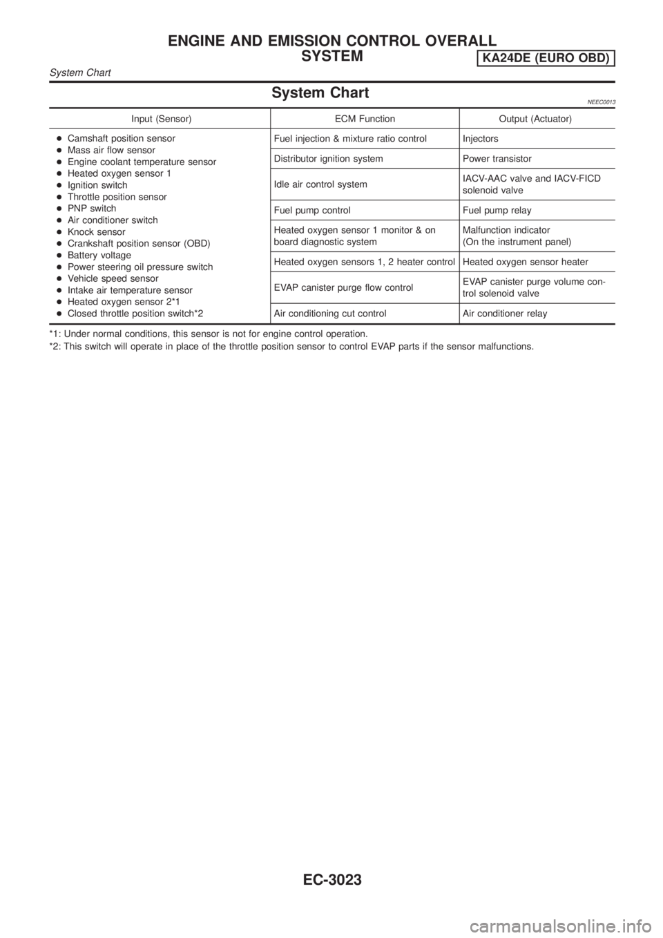
System ChartNEEC0013
Input (Sensor) ECM Function Output (Actuator)
+Camshaft position sensor
+Mass air flow sensor
+Engine coolant temperature sensor
+Heated oxygen sensor 1
+Ignition switch
+Throttle position sensor
+PNP switch
+Air conditioner switch
+Knock sensor
+Crankshaft position sensor (OBD)
+Battery voltage
+Power steering oil pressure switch
+Vehicle speed sensor
+Intake air temperature sensor
+Heated oxygen sensor 2*1
+Closed throttle position switch*2Fuel injection & mixture ratio control Injectors
Distributor ignition system Power transistor
Idle air control systemIACV-AAC valve and IACV-FICD
solenoid valve
Fuel pump control Fuel pump relay
Heated oxygen sensor 1 monitor & on
board diagnostic systemMalfunction indicator
(On the instrument panel)
Heated oxygen sensors 1, 2 heater control Heated oxygen sensor heater
EVAP canister purge flow controlEVAP canister purge volume con-
trol solenoid valve
Air conditioning cut control Air conditioner relay
*1: Under normal conditions, this sensor is not for engine control operation.
*2: This switch will operate in place of the throttle position sensor to control EVAP parts if the sensor malfunctions.
ENGINE AND EMISSION CONTROL OVERALL
SYSTEM
KA24DE (EURO OBD)
System Chart
EC-3023
Page 60 of 1306

SEF500V
Fast Idle Cam (FIC)
COMPONENT DESCRIPTIONNEEC0502The FIC is installed on the throttle body to maintain adequate
engine speed while the engine is cold. It is operated by a volumet-
ric change in wax located inside the thermo-element. The thermo-
element is operated by engine coolant temperature.
For inspection refer to ªTROUBLE DIAGNOSIS-BASIC
INSPECTIONº, ªBasic Inspectionº, EC-3086.
Idle Speed/Ignition Timing/Idle Mixture Ratio
Adjustment
NEEC0028PREPARATIONNEEC0028S05+Make sure that the following parts are in good order.
a)Battery
b)Ignition system
c)Engine oil and coolant levels
d)Fuses
e)ECM harness connector
f)Vacuum hoses
g)Air intake system
(Oil filler cap, oil level gauge, etc.)
h)Fuel pressure
i)Engine compression
j)Throttle valve
k)EVAP system
+On models equipped with air conditioner, checks should be carried out while the air conditioner is
ªOFFº.
+When measuring ªCOº percentage, insert probe more than 40 cm (15.7 in) into tail pipe.
+Turn off headlamps, heater blower.
+Keep front wheels pointed straight ahead.
BASIC SERVICE PROCEDUREKA24DE (EURO OBD)
Fast Idle Cam (FIC)
EC-3035
Page 77 of 1306
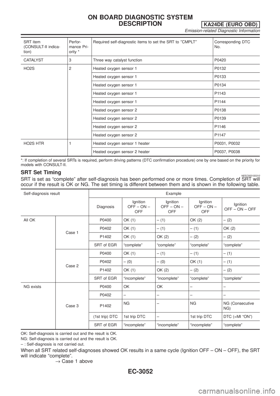
SRT item
(CONSULT-II indica-
tion)Perfor-
mance Pri-
ority *Required self-diagnostic items to set the SRT to²CMPLT²Corresponding DTC
No.
CATALYST 3 Three way catalyst function P0420
HO2S 2 Heated oxygen sensor 1 P0132
Heated oxygen sensor 1 P0133
Heated oxygen sensor 1 P0134
Heated oxygen sensor 1 P1143
Heated oxygen sensor 1 P1144
Heated oxygen sensor 2 P0138
Heated oxygen sensor 2 P0139
Heated oxygen sensor 2 P1146
Heated oxygen sensor 2 P1147
HO2S HTR 1 Heated oxygen sensor 1 heater P0031, P0032
Heated oxygen sensor 2 heater P0037, P0038
*: If completion of several SRTs is required, perform driving patterns (DTC confirmation procedure) one by one based on the priority for
models with CONSULT-II.
SRT Set TimingNEEC0031S0310SRT is set as ªcompleteº after self-diagnosis has been performed one or more times. Completion of SRT will
occur if the result is OK or NG. The set timing is different between them and is shown in the following table.
Self-diagnosis result Example
DiagnosisIgnition
OFF±ON±
OFFIgnition
OFF±ON±
OFFIgnition
OFF±ON±
OFFIgnition
OFF±ON±OFF
All OK
Case 1P0400 OK (1) ± (1) OK (2) ± (2)
P0402 OK (1) ± (1) ± (1) OK (2)
P1402 OK (1) OK (2) ± (2) ± (2)
SRT of EGR ªcompleteº ªcompleteº ªcompleteº ªcompleteº
Case 2P0400 OK (1) ± (1) ± (1) ± (1)
P0402 ± (0) ± (0) OK (1) ± (1)
P1402 OK (1) OK (2) ± (2) ± (2)
SRT of EGR ªincompleteº ªincompleteº ªcompleteº ªcompleteº
NG exists
Case 3P0400 OK OK ± ±
P0402±±±±
P1402NG ± NG NG (Consecutive
NG)
(1st trip) DTC 1st trip DTC ± 1st trip DTC DTC (=MI ªONº)
SRT of EGR ªincompleteº ªincompleteº ªincompleteº ªcompleteº
OK: Self-diagnosis is carried out and the result is OK.
NG: Self-diagnosis is carried out and the result is OK.
± : Self-diagnosis is not carried out.
When all SRT related self-diagnoses showed OK results in a same cycle (Ignition OFF ± ON ± OFF), the SRT
will indicate ªcompleteº.
®Case 1 above
ON BOARD DIAGNOSTIC SYSTEM
DESCRIPTION
KA24DE (EURO OBD)
Emission-related Diagnostic Information
EC-3052
Page 83 of 1306
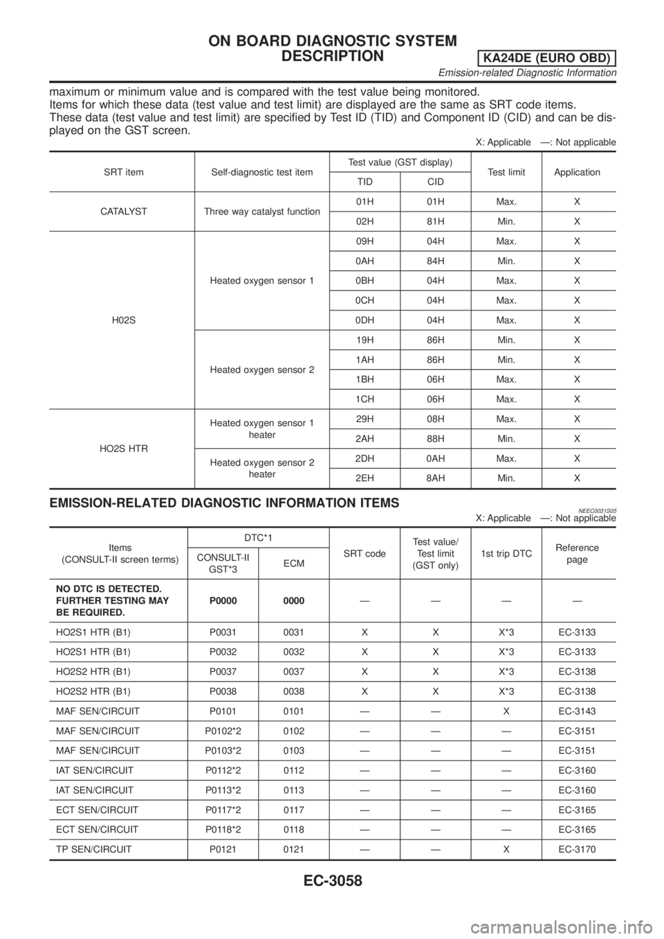
maximum or minimum value and is compared with the test value being monitored.
Items for which these data (test value and test limit) are displayed are the same as SRT code items.
These data (test value and test limit) are specified by Test ID (TID) and Component ID (CID) and can be dis-
played on the GST screen.
X: Applicable Ð: Not applicable
SRT item Self-diagnostic test itemTest value (GST display)
Test limit Application
TID CID
CATALYST Three way catalyst function01H 01H Max. X
02H 81H Min. X
H02SHeated oxygen sensor 109H 04H Max. X
0AH 84H Min. X
0BH 04H Max. X
0CH 04H Max. X
0DH 04H Max. X
Heated oxygen sensor 219H 86H Min. X
1AH 86H Min. X
1BH 06H Max. X
1CH 06H Max. X
HO2S HTRHeated oxygen sensor 1
heater29H 08H Max. X
2AH 88H Min. X
Heated oxygen sensor 2
heater2DH 0AH Max. X
2EH 8AH Min. X
EMISSION-RELATED DIAGNOSTIC INFORMATION ITEMSNEEC0031S05X: Applicable Ð: Not applicable
Items
(CONSULT-II screen terms)DTC*1
SRT codeTest value/
Test limit
(GST only)1st trip DTCReference
page CONSULT-II
GST*3ECM
NO DTC IS DETECTED.
FURTHER TESTING MAY
BE REQUIRED.P0000 0000ÐÐÐÐ
HO2S1 HTR (B1) P0031 0031 X X X*3 EC-3133
HO2S1 HTR (B1) P0032 0032 X X X*3 EC-3133
HO2S2 HTR (B1) P0037 0037 X X X*3 EC-3138
HO2S2 HTR (B1) P0038 0038 X X X*3 EC-3138
MAF SEN/CIRCUIT P0101 0101 Ð Ð X EC-3143
MAF SEN/CIRCUIT P0102*2 0102 Ð Ð Ð EC-3151
MAF SEN/CIRCUIT P0103*2 0103 Ð Ð Ð EC-3151
IAT SEN/CIRCUIT P0112*2 0112 Ð Ð Ð EC-3160
IAT SEN/CIRCUIT P0113*2 0113 Ð Ð Ð EC-3160
ECT SEN/CIRCUIT P0117*2 0117 Ð Ð Ð EC-3165
ECT SEN/CIRCUIT P0118*2 0118 Ð Ð Ð EC-3165
TP SEN/CIRCUIT P0121 0121 Ð Ð X EC-3170
ON BOARD DIAGNOSTIC SYSTEM
DESCRIPTION
KA24DE (EURO OBD)
Emission-related Diagnostic Information
EC-3058
Page 97 of 1306
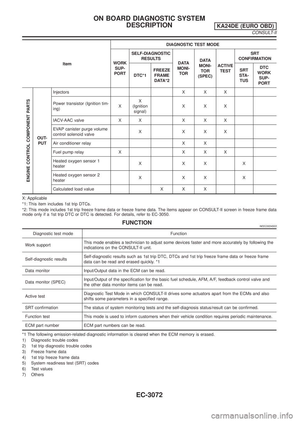
ItemDIAGNOSTIC TEST MODE
WORK
SUP-
PORTSELF-DIAGNOSTIC
RESULTS
DATA
MONI-
TORDATA
MONI-
TOR
(SPEC)ACTIVE
TESTSRT
CONFIRMATION
DTC*1FREEZE
FRAME
DATA*2SRT
STA-
TUSDTC
WORK
SUP-
PORT
ENGINE CONTROL COMPONENT PARTS
OUT-
PUTInjectors X X X
Power transistor (Ignition tim-
ing)XX
(Ignition
signal)XXX
IACV-AAC valve X X X X X
EVAP canister purge volume
control solenoid valveXXXX
Air conditioner relay X X
Fuel pump relay X X X X
Heated oxygen sensor 1
heaterXXXX
Heated oxygen sensor 2
heaterXXXX
Calculated load value X X X
X: Applicable
*1: This item includes 1st trip DTCs.
*2: This mode includes 1st trip freeze frame data or freeze frame data. The items appear on CONSULT-II screen in freeze frame data
mode only if a 1st trip DTC or DTC is detected. For details, refer to EC-3050.
FUNCTIONNEEC0034S03
Diagnostic test mode Function
Work supportThis mode enables a technician to adjust some devices faster and more accurately by following the
indications on the CONSULT-II unit.
Self-diagnostic resultsSelf-diagnostic results such as 1st trip DTC, DTCs and 1st trip freeze frame data or freeze frame
data can be read and erased quickly. *1
Data monitor Input/Output data in the ECM can be read.
Data monitor (SPEC)Input/Output of the specification for the basic fuel schedule, AFM, A/F, feedback control valve and
the other data monitor items can be read.
Active testDiagnostic Test Mode in which CONSULT-II drives some actuators apart from the ECMs and also
shifts some parameters in a specified range.
SRT confirmation The status of system monitoring tests and the self-diagnosis status/result can be confirmed.
Function test This mode is used to inform customers when their vehicle condition requires periodic maintenance.
ECM part number ECM part numbers can be read.
*1 The following emission-related diagnostic information is cleared when the ECM memory is erased.
1) Diagnostic trouble codes
2) 1st trip diagnostic trouble codes
3) Freeze frame data
4) 1st trip freeze frame data
5) System readiness test (SRT) codes
6) Test values
7) Others
ON BOARD DIAGNOSTIC SYSTEM
DESCRIPTION
KA24DE (EURO OBD)
CONSULT-II
EC-3072