2001 NISSAN PICK-UP power steering
[x] Cancel search: power steeringPage 29 of 1306

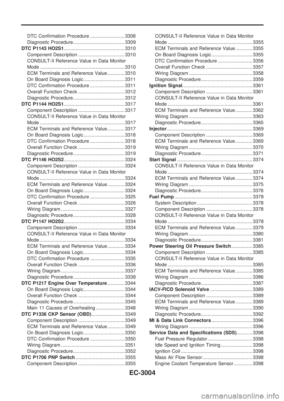
DTC Confirmation Procedure .......................... 3308
Diagnostic Procedure....................................... 3309
DTC P1143 HO2S1.............................................. 3310
Component Description ................................... 3310
CONSULT-II Reference Value in Data Monitor
Mode ................................................................ 3310
ECM Terminals and Reference Value ............. 3310
On Board Diagnosis Logic ............................... 3311
DTC Confirmation Procedure .......................... 3311
Overall Function Check ................................... 3312
Diagnostic Procedure....................................... 3312
DTC P1144 HO2S1.............................................. 3317
Component Description ................................... 3317
CONSULT-II Reference Value in Data Monitor
Mode ................................................................ 3317
ECM Terminals and Reference Value ............. 3317
On Board Diagnosis Logic ............................... 3318
DTC Confirmation Procedure .......................... 3318
Overall Function Check ................................... 3319
Diagnostic Procedure....................................... 3319
DTC P1146 HO2S2.............................................. 3324
Component Description ................................... 3324
CONSULT-II Reference Value in Data Monitor
Mode ................................................................ 3324
ECM Terminals and Reference Value ............. 3324
On Board Diagnosis Logic ............................... 3324
DTC Confirmation Procedure .......................... 3325
Overall Function Check ................................... 3326
Wiring Diagram ................................................ 3327
Diagnostic Procedure....................................... 3328
DTC P1147 HO2S2.............................................. 3334
Component Description ................................... 3334
CONSULT-II Reference Value in Data Monitor
Mode ................................................................ 3334
ECM Terminals and Reference Value ............. 3334
On Board Diagnosis Logic ............................... 3334
DTC Confirmation Procedure .......................... 3335
Overall Function Check ................................... 3336
Wiring Diagram ................................................ 3337
Diagnostic Procedure....................................... 3338
DTC P1217 Engine Over Temperature............. 3344
On Board Diagnosis Logic ............................... 3344
Overall Function Check ................................... 3344
Diagnostic Procedure....................................... 3345
Main 11 Causes of Overheating ...................... 3348
DTC P1336 CKP Sensor (OBD)......................... 3349
Component Description ................................... 3349
ECM Terminals and Reference Value ............. 3349
On Board Diagnosis Logic ............................... 3350
DTC Confirmation Procedure .......................... 3350
Wiring Diagram ................................................ 3351
Diagnostic Procedure....................................... 3352
DTC P1706 PNP Switch..................................... 3355
Component Description ................................... 3355CONSULT-II Reference Value in Data Monitor
Mode ................................................................ 3355
ECM Terminals and Reference Value ............. 3355
On Board Diagnosis Logic ............................... 3355
DTC Confirmation Procedure .......................... 3356
Overall Function Check ................................... 3357
Wiring Diagram ................................................ 3358
Diagnostic Procedure....................................... 3359
Ignition Signal..................................................... 3361
Component Description ................................... 3361
CONSULT-II Reference Value in Data Monitor
Mode ................................................................ 3361
ECM Terminals and Reference Value ............. 3362
Wiring Diagram ................................................ 3363
Diagnostic Procedure....................................... 3365
Injector................................................................. 3369
Component Description ................................... 3369
ECM Terminals and Reference Value ............. 3369
Wiring Diagram ................................................ 3370
Diagnostic Procedure....................................... 3371
Start Signal......................................................... 3374
CONSULT-II Reference Value in Data Monitor
Mode ................................................................ 3374
ECM Terminals and Reference Value ............. 3374
Wiring Diagram ................................................ 3375
Diagnostic Procedure....................................... 3376
Fuel Pump........................................................... 3378
System Description .......................................... 3378
Component Description ................................... 3378
CONSULT-II Reference Value in Data Monitor
Mode ................................................................ 3378
ECM Terminals and Reference Value ............. 3379
Wiring Diagram ................................................ 3380
Diagnostic Procedure....................................... 3381
Power Steering Oil Pressure Switch................ 3385
Component Description ................................... 3385
CONSULT-II Reference Value in Data Monitor
Mode ................................................................ 3385
ECM Terminals and Reference Value ............. 3385
Wiring Diagram ................................................ 3386
Diagnostic Procedure....................................... 3387
IACV-FICD Solenoid Valve................................ 3389
Component Description ................................... 3389
ECM Terminals and Reference Value ............. 3389
Wiring Diagram ................................................ 3390
Diagnostic Procedure....................................... 3392
MI & Data Link Connectors............................... 3396
Wiring Diagram ................................................ 3396
Service Data and Specifications (SDS)............ 3398
Fuel Pressure Regulator .................................. 3398
Idle Speed and Ignition Timing ........................ 3398
Ignition Coil ...................................................... 3398
Mass Air Flow Sensor...................................... 3398
Engine Coolant Temperature Sensor .............. 3398
EC-3004
Page 48 of 1306

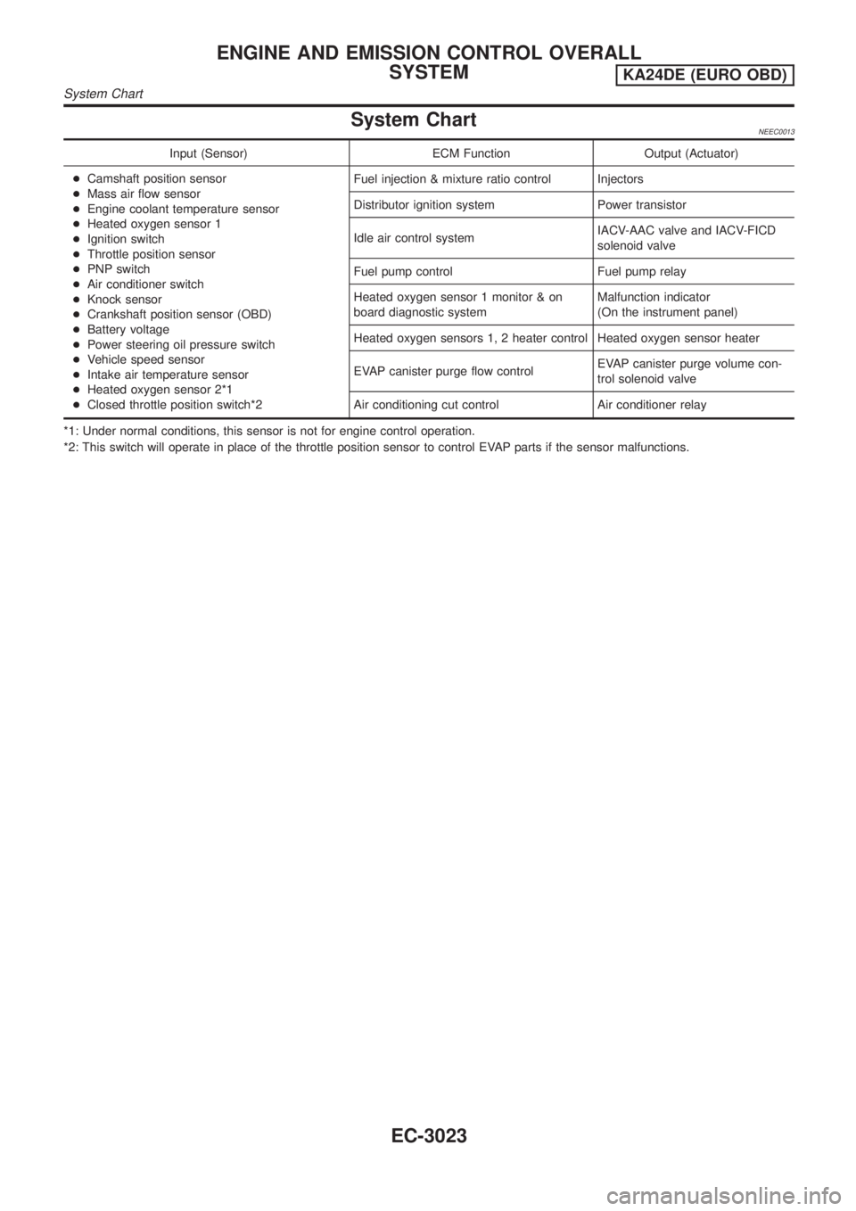
System ChartNEEC0013
Input (Sensor) ECM Function Output (Actuator)
+Camshaft position sensor
+Mass air flow sensor
+Engine coolant temperature sensor
+Heated oxygen sensor 1
+Ignition switch
+Throttle position sensor
+PNP switch
+Air conditioner switch
+Knock sensor
+Crankshaft position sensor (OBD)
+Battery voltage
+Power steering oil pressure switch
+Vehicle speed sensor
+Intake air temperature sensor
+Heated oxygen sensor 2*1
+Closed throttle position switch*2Fuel injection & mixture ratio control Injectors
Distributor ignition system Power transistor
Idle air control systemIACV-AAC valve and IACV-FICD
solenoid valve
Fuel pump control Fuel pump relay
Heated oxygen sensor 1 monitor & on
board diagnostic systemMalfunction indicator
(On the instrument panel)
Heated oxygen sensors 1, 2 heater control Heated oxygen sensor heater
EVAP canister purge flow controlEVAP canister purge volume con-
trol solenoid valve
Air conditioning cut control Air conditioner relay
*1: Under normal conditions, this sensor is not for engine control operation.
*2: This switch will operate in place of the throttle position sensor to control EVAP parts if the sensor malfunctions.
ENGINE AND EMISSION CONTROL OVERALL
SYSTEM
KA24DE (EURO OBD)
System Chart
EC-3023
Page 49 of 1306

Multiport Fuel Injection (MFI) System
DESCRIPTIONNEEC0014Input/Output Signal ChartNEEC0014S01
Sensor Input Signal to ECMECM func-
tionActuator
Camshaft position sensor Engine speed and piston position
Fuel injec-
tion & mix-
ture ratio
controlInjector Mass air flow sensor Amount of intake air
Engine coolant temperature sensor Engine coolant temperature
Heated oxygen sensor 1 Density of oxygen in exhaust gas
Throttle position sensorThrottle position
Throttle valve idle position
PNP switch Gear position
Vehicle speed sensor Vehicle speed
Ignition switch Start signal
Air conditioner switch Air conditioner operation
Knock sensor Engine knocking condition
Battery Battery voltage
Power steering oil pressure switch Power steering operation
Heated oxygen sensor 2* Density of oxygen in exhaust gas
* Under normal conditions, this sensor is not for engine control operation.
Basic Multiport Fuel Injection SystemNEEC0014S02The amount of fuel injected from the fuel injector is determined by the ECM. The ECM controls the length of
time the valve remains open (injection pulse duration). The amount of fuel injected is a program value in the
ECM memory. The program value is preset by engine operating conditions. These conditions are determined
by input signals (for engine speed and intake air) from both the camshaft position sensor and the mass air
flow sensor.
Various Fuel Injection Increase/Decrease CompensationNEEC0014S03In addition, the amount of fuel injected is compensated to improve engine performance under various oper-
ating conditions as listed below.
+During warm-up
+When starting the engine
+During acceleration
+Hot-engine operation
+High-load, high-speed operation
+During deceleration
+During high engine speed operation
ENGINE AND EMISSION BASIC CONTROL SYSTEM
DESCRIPTION
KA24DE (EURO OBD)
Multiport Fuel Injection (MFI) System
EC-3024
Page 53 of 1306

Air Conditioning Cut Control
DESCRIPTION=NEEC0016Input/Output Signal ChartNEEC0016S01
Sensor Input Signal to ECMECM func-
tionActuator
Air conditioner switch Air conditioner ªONº signal
Air condi-
tioner cut
controlAir conditioner relay Throttle position sensor Throttle valve opening angle
Camshaft position sensor Engine speed
Engine coolant temperature sensor Engine coolant temperature
Ignition switch Start signal
Vehicle speed sensor Vehicle speed
Power steering oil pressure switch Power steering operation
System DescriptionNEEC0016S02This system improves engine operation when the air conditioner is used.
Under the following conditions, the air conditioner is turned off.
+When the accelerator pedal is fully depressed.
+When cranking the engine.
+When the engine coolant temperature becomes excessively high.
+When operating power steering and air conditioner during low engine speed or when fully releasing accel-
erator pedal.
+When engine speed is excessively low.
Fuel Cut Control (at no load & high engine
speed)
DESCRIPTIONNEEC0017Input/Output Signal ChartNEEC0017S01
Sensor Input Signal to ECMECM func-
tionActuator
Vehicle speed sensor Vehicle speed
Fuel cut
controlInjectors PNP switch Neutral position
Throttle position sensor Throttle position
Camshaft position sensor Engine speed
If the engine speed is above 3,000 rpm with no load, (for example, in Neutral and engine speed over 3,000
rpm) fuel will be cut off after some time. The exact time when the fuel is cut off varies based on engine speed.
Fuel cut will operate until the engine speed reaches 1,500 rpm, then fuel cut is cancelled.
NOTE:
This function is different from deceleration control listed under ªMultiport Fuel Injection (MFI) Systemº,
EC-3024.
ENGINE AND EMISSION BASIC CONTROL SYSTEM
DESCRIPTION
KA24DE (EURO OBD)
Air Conditioning Cut Control
EC-3028
Page 96 of 1306

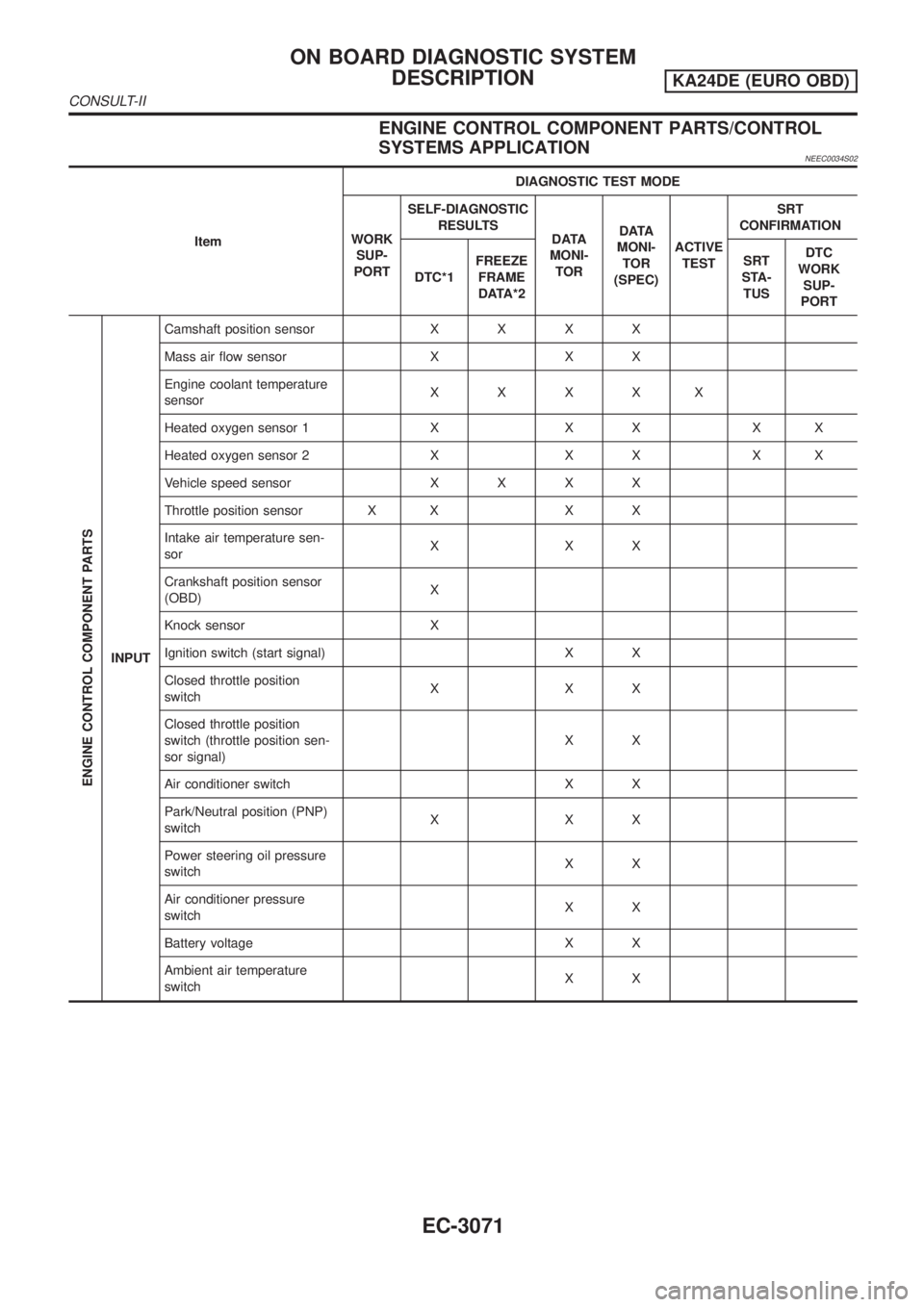
ENGINE CONTROL COMPONENT PARTS/CONTROL
SYSTEMS APPLICATION
NEEC0034S02
ItemDIAGNOSTIC TEST MODE
WORK
SUP-
PORTSELF-DIAGNOSTIC
RESULTS
DATA
MONI-
TORDATA
MONI-
TOR
(SPEC)ACTIVE
TESTSRT
CONFIRMATION
DTC*1FREEZE
FRAME
DATA*2SRT
STA-
TUSDTC
WORK
SUP-
PORT
ENGINE CONTROL COMPONENT PARTS
INPUTCamshaft position sensorXXXX
Mass air flow sensor X X X
Engine coolant temperature
sensorXXXXX
Heated oxygen sensor 1 X X X X X
Heated oxygen sensor 2 X X X X X
Vehicle speed sensorXXXX
Throttle position sensor X X X X
Intake air temperature sen-
sorXXX
Crankshaft position sensor
(OBD)X
Knock sensor X
Ignition switch (start signal) X X
Closed throttle position
switchXXX
Closed throttle position
switch (throttle position sen-
sor signal)XX
Air conditioner switch X X
Park/Neutral position (PNP)
switchXXX
Power steering oil pressure
switchXX
Air conditioner pressure
switchXX
Battery voltage X X
Ambient air temperature
switchXX
ON BOARD DIAGNOSTIC SYSTEM
DESCRIPTION
KA24DE (EURO OBD)
CONSULT-II
EC-3071
Page 100 of 1306
![NISSAN PICK-UP 2001 Repair Manual Monitored item [Unit]ECM
input
signalsMain
signalsDescription Remarks
THRTL POS SEN [V]jj+The throttle position sensor signal volt-
age is displayed.
INT/A TEMP SE
[ÉC] or [ÉF]jj+The intake air temp NISSAN PICK-UP 2001 Repair Manual Monitored item [Unit]ECM
input
signalsMain
signalsDescription Remarks
THRTL POS SEN [V]jj+The throttle position sensor signal volt-
age is displayed.
INT/A TEMP SE
[ÉC] or [ÉF]jj+The intake air temp](/manual-img/5/57372/w960_57372-99.png)
Monitored item [Unit]ECM
input
signalsMain
signalsDescription Remarks
THRTL POS SEN [V]jj+The throttle position sensor signal volt-
age is displayed.
INT/A TEMP SE
[ÉC] or [ÉF]jj+The intake air temperature determined
by the signal voltage of the intake air
temperature sensor is indicated.
START SIGNAL
[ON/OFF]jj+Indicates [ON/OFF] condition from the
starter signal.+After starting the engine, [OFF] is dis-
played regardless of the starter sig-
nal.
CLSD THL POS
[ON/OFF]jj+Indicates idle position [ON/OFF] com-
puted by ECM according to the throttle
position sensor signal.
CLSD THL/P SW
[ON/OFF]j+Indicates mechanical contact [ON/OFF]
condition of the closed throttle position
switch.
AIR COND SIG
[ON/OFF]jj+Indicates [ON/OFF] condition of the air
conditioner switch as determined by
the air conditioning signal.
P/N POSI SW
[ON/OFF]jj+Indicates [ON/OFF] condition from the
PNP switch signal.
PW/ST SIGNAL
[ON/OFF]jj+Indicates [ON/OFF] condition of the
power steering oil pressure switch
determined by the power steering oil
pressure switch signal.
AMB TEMP SW
[ON/OFF]j+Indicates [ON/OFF] condition from the
ambient air temperature switch signal.
IGNITION SW
[ON/OFF]j+Indicates [ON/OFF] condition from igni-
tion switch.
INJ PULSE-B1 [msec]j+Indicates the actual fuel injection pulse
width compensated by ECM according
to the input signals.+When the engine is stopped, a cer-
tain computed value is indicated.
IGN TIMING [BTDC]j+Indicates the ignition timing computed
by ECM according to the input signals.
CAL/LD VALUE [%]+ªCalculated load valueº indicates the
value of the current airflow divided by
peak airflow.
ABSOL TH´P/S [%]+ªAbsolute throttle position sensorº indi-
cates the throttle opening computed by
ECM according to the signal voltage of
the throttle position sensor.
MASS AIRFLOW
[g´m/s]+Indicates the mass airflow computed by
ECM according to the signal voltage of
the mass air flow sensor.
IACV-AAC/V [%]j+Indicates the IACV-AAC valve control
value computed by ECM according to
the input signals.
PURG VOL C/V [%]+Indicates the EVAP canister purge vol-
ume control value computed by the
ECM according to the input signals.
+The opening becomes larger as the
value increases.
ON BOARD DIAGNOSTIC SYSTEM
DESCRIPTION
KA24DE (EURO OBD)
CONSULT-II
EC-3075
Page 128 of 1306

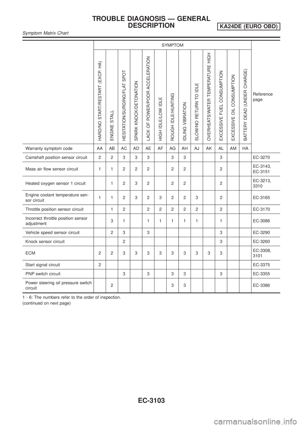
SYMPTOM
Reference
page
HARD/NO START/RESTART (EXCP. HA)
ENGINE STALL
HESITATION/SURGING/FLAT SPOT
SPARK KNOCK/DETONATION
LACK OF POWER/POOR ACCELERATION
HIGH IDLE/LOW IDLE
ROUGH IDLE/HUNTING
IDLING VIBRATION
SLOW/NO RETURN TO IDLE
OVERHEATS/WATER TEMPERATURE HIGH
EXCESSIVE FUEL CONSUMPTION
EXCESSIVE OIL CONSUMPTION
BATTERY DEAD (UNDER CHARGE)
Warranty symptom code AA AB AC AD AE AF AG AH AJ AK AL AM HA
Camshaft position sensor circuit22333 33 3EC-3270
Mass air flow sensor circuit11222 22 2EC-3143,
EC-3151
Heated oxygen sensor 1 circuit1232 22 2EC-3213,
3310
Engine coolant temperature sen-
sor circuit112323223 2EC-3165
Throttle position sensor circuit 1 222222 2EC-3170
Incorrect throttle position sensor
adjustment31 11111 1EC-3086
Vehicle speed sensor circuit 2 3 3 3 EC-3290
Knock sensor circuit 2 3 EC-3260
ECM 22333333333EC-3308,
3101
Start signal circuit 2EC-3375
PNP switch circuit 3 3 3 3 3 EC-3355
Power steering oil pressure switch
circuit2 3 3 EC-3386
1 - 6: The numbers refer to the order of inspection.
(continued on next page)
TROUBLE DIAGNOSIS Ð GENERAL
DESCRIPTION
KA24DE (EURO OBD)
Symptom Matrix Chart
EC-3103
Page 139 of 1306
![NISSAN PICK-UP 2001 Repair Manual TERMI-
NAL
NO.WIRE
COLORITEM CONDITION DATA (DC Voltage)
23 G Throttle position sensor[Ignition switch ON]
+Warm-up condition
+Accelerator pedal fully released0.2 - 0.8V
[Ignition switch ON]
+Accelera NISSAN PICK-UP 2001 Repair Manual TERMI-
NAL
NO.WIRE
COLORITEM CONDITION DATA (DC Voltage)
23 G Throttle position sensor[Ignition switch ON]
+Warm-up condition
+Accelerator pedal fully released0.2 - 0.8V
[Ignition switch ON]
+Accelera](/manual-img/5/57372/w960_57372-138.png)
TERMI-
NAL
NO.WIRE
COLORITEM CONDITION DATA (DC Voltage)
23 G Throttle position sensor[Ignition switch ON]
+Warm-up condition
+Accelerator pedal fully released0.2 - 0.8V
[Ignition switch ON]
+Accelerator pedal fully depressed3.5 - 4.5V
24 W/L Ignition switch[Ignition switch OFF]0V
[Ignition switch ON]BATTERY VOLTAGE
(11 - 14V)
25 B ECM ground[Engine is running]
+Idle speedEngine ground
28 LG/BThrottle position switch
(Closed position)[Ignition switch ON]
+Warm-up condition
+Accelerator pedal releasedBATTERY VOLTAGE
(11 - 14V)
[Ignition switch ON]
+Accelerator pedal depressedApproximately 0V
29 W/L Vehicle speed sensor[Engine is running]
+Lift up the vehicle
+In 2nd gear position
+40 km/h (25 MPH)1-4V
SEF111V
32 B ECM ground[Engine is running]
+Idle speedEngine ground
39 SBPower steering oil
pressure switch[Engine is running]
+Steering wheel is fully turnedApproximately 0V
[Engine is running]
+Steering wheel is not turnedApproximately 5V
42 G/B Sensors' power supply[Ignition switch ON]Approximately 5V
43 B Sensors' ground[Engine is running]
+Idle speedApproximately 0V
TROUBLE DIAGNOSIS Ð GENERAL
DESCRIPTION
KA24DE (EURO OBD)
ECM Terminals and Reference Value
EC-3114