2001 NISSAN PICK-UP power steering
[x] Cancel search: power steeringPage 899 of 1306
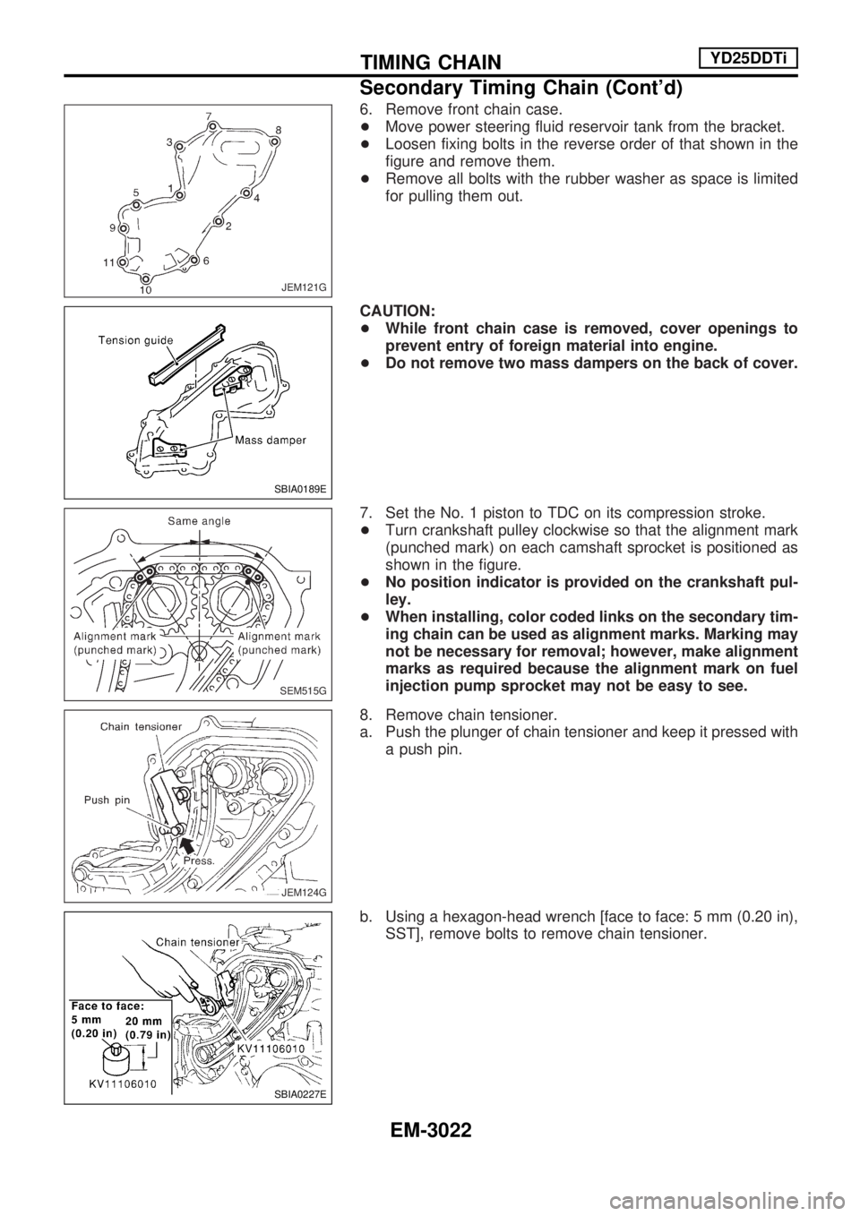
6. Remove front chain case.
+Move power steering fluid reservoir tank from the bracket.
+Loosen fixing bolts in the reverse order of that shown in the
figure and remove them.
+Remove all bolts with the rubber washer as space is limited
for pulling them out.
CAUTION:
+While front chain case is removed, cover openings to
prevent entry of foreign material into engine.
+Do not remove two mass dampers on the back of cover.
7. Set the No. 1 piston to TDC on its compression stroke.
+Turn crankshaft pulley clockwise so that the alignment mark
(punched mark) on each camshaft sprocket is positioned as
shown in the figure.
+No position indicator is provided on the crankshaft pul-
ley.
+When installing, color coded links on the secondary tim-
ing chain can be used as alignment marks. Marking may
not be necessary for removal; however, make alignment
marks as required because the alignment mark on fuel
injection pump sprocket may not be easy to see.
8. Remove chain tensioner.
a. Push the plunger of chain tensioner and keep it pressed with
a push pin.
b. Using a hexagon-head wrench [face to face: 5 mm (0.20 in),
SST], remove bolts to remove chain tensioner.
JEM121G
SBIA0189E
SEM515G
JEM124G
SBIA0227E
TIMING CHAINYD25DDTi
Secondary Timing Chain (Cont'd)
EM-3022
Page 1030 of 1306
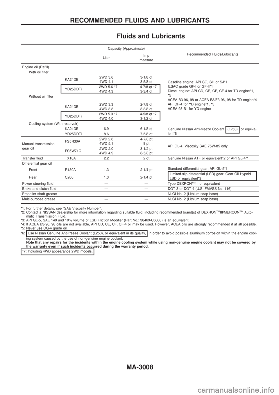
Fluids and Lubricants
Capacity (Approximate)
Recommended Fluids/Lubricants
LiterImp
measure
Engine oil (Refill)
With oil filter
Gasoline engine: API SG, SH or SJ*1
ILSAC grade GF-I or GF-II*1
Diesel engine: API CD, CE, CF, CF-4 for TD engine*1,
*5
ACEA B3-96, 98 or ACEA B3/E3 96, 98 for TD engine*4
API CF-4 for YD engine*1, *5
ACEA 98-B1 for YD engine KA24DE2WD 3.6
4WD 4.13-1/8 qt
3-5/8 qt
YD25DDTi2WD 5.6 *7
4WD 4.34-7/8 qt *7
3-3/4 qt
Without oil filter
KA24DE2WD 3.3
4WD 3.82-7/8 qt
3-3/8 qt
YD25DDTi2WD 5.3 *7
4WD 4.04-5/8 qt *7
3-1/2 qt
Cooling system (With reservoir)
KA24DE 6.9 6-1/8 qt
Genuine Nissan Anti-freeze Coolant (L250)
or equiva-
lent*6
YD25DDTi 8.6 7-5/8 qt
Manual transmission
gear oilFS5R30A2WD 2.8
4WD 5.14-7/8 pt
9pt
API GL-4, Viscosity SAE 75W-85 only
FS5W71C2WD 2.0
4WD 4.93-1/2 pt
8-5/8 pt
Transfer fluid TX10A 2.2 2 qt Genuine Nissan ATF or equivalent*2 or API GL-4*1
Differential gear oil
Front R180A 1.3 2-1/4 pt
Standard differential gear: API GL-5*1
Limited-slip differential (LSD) gear: Gear Oil Hypoid
LSD or equivalent*3 Rear C200 1.3 2-1/4 pt
Power steering fluid Ð Ð Type DEXRON
TMIII or equivalent
Brake and clutch fluid Ð Ð DOT 3 or DOT 4 (U.S. FMVSS No. 116)
Propeller shaft grease Ð Ð NLGI No. 2 (Lithium soap base)
Multi-purpose grease Ð Ð NLGI No. 2 (Lithium soap base)
*1: For further details, see ªSAE Viscosity Numberº.
*2: Contact a NISSAN dealership for more information regarding suitable fluid, including recommended brand(s) of DEXRONTMIII/MERCONTMAuto-
matic Transmission Fluid.
*3: API GL-5, SAE 140 and 10% volume of LSD Friction Modifier (Part No.: 38469-C6000) is an equivalent.
*4: If ACEA B3-96, 98 oils are not available, API CD, CE, CF, CF-4 oil may be used. However, ACEA oils are strongly recommended if at all possible.
*5: Never use CG-4 grade oil.
*6: Use Nissan Genuine Anti-freeze Coolant (L250), or equivalent in its quality,
in order to avoid possible aluminum corrosion within the engine cool-
ing system caused by the use of non-genuine engine coolant.
Note that any repairs for the incidents within the engine cooling system while using non-genuine engine coolant may not be covered by
the warranty even if such incidents occurred during the warranty period.
*7: Including 4WD appearance 2WD models.
RECOMMENDED FLUIDS AND LUBRICANTS
MA-3008
Page 1033 of 1306
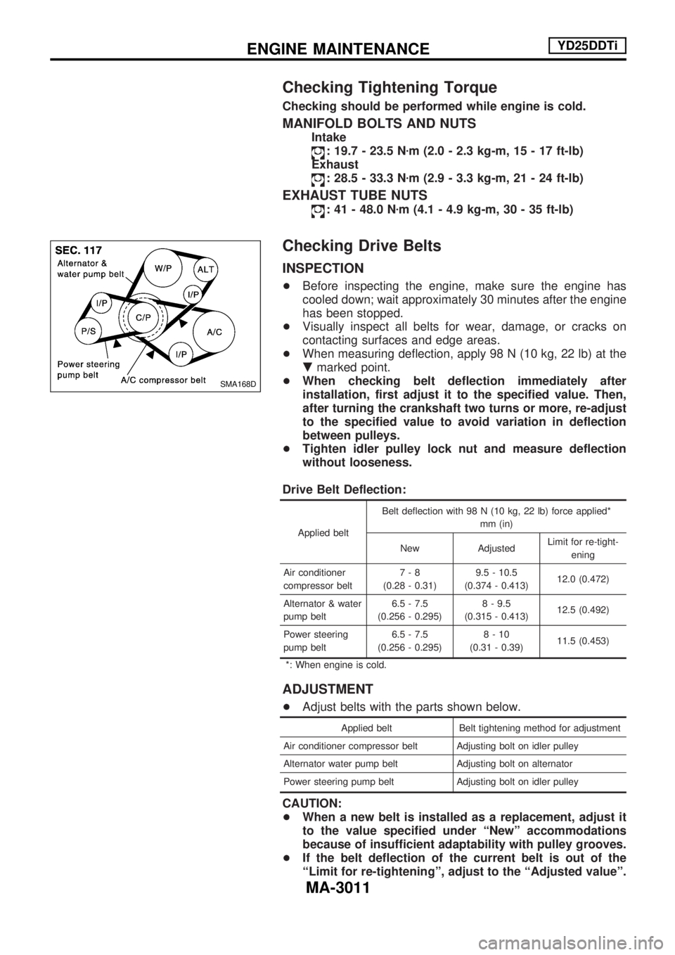
Checking Tightening Torque
Checking should be performed while engine is cold.
MANIFOLD BOLTS AND NUTS
Intake
: 19.7 - 23.5 Nzm (2.0 - 2.3 kg-m, 15 - 17 ft-lb)
Exhaust
: 28.5 - 33.3 Nzm (2.9 - 3.3 kg-m, 21 - 24 ft-lb)
EXHAUST TUBE NUTS
: 41 - 48.0 Nzm (4.1 - 4.9 kg-m, 30 - 35 ft-lb)
Checking Drive Belts
INSPECTION
+Before inspecting the engine, make sure the engine has
cooled down; wait approximately 30 minutes after the engine
has been stopped.
+Visually inspect all belts for wear, damage, or cracks on
contacting surfaces and edge areas.
+When measuring deflection, apply 98 N (10 kg, 22 lb) at the
.marked point.
+When checking belt deflection immediately after
installation, first adjust it to the specified value. Then,
after turning the crankshaft two turns or more, re-adjust
to the specified value to avoid variation in deflection
between pulleys.
+Tighten idler pulley lock nut and measure deflection
without looseness.
Drive Belt Deflection:
Applied beltBelt deflection with 98 N (10 kg, 22 lb) force applied*
mm (in)
New AdjustedLimit for re-tight-
ening
Air conditioner
compressor belt7-8
(0.28 - 0.31)9.5 - 10.5
(0.374 - 0.413)12.0 (0.472)
Alternator & water
pump belt6.5 - 7.5
(0.256 - 0.295)8 - 9.5
(0.315 - 0.413)12.5 (0.492)
Power steering
pump belt6.5 - 7.5
(0.256 - 0.295)8-10
(0.31 - 0.39)11.5 (0.453)
*: When engine is cold.
ADJUSTMENT
+Adjust belts with the parts shown below.
Applied belt Belt tightening method for adjustment
Air conditioner compressor belt Adjusting bolt on idler pulley
Alternator water pump belt Adjusting bolt on alternator
Power steering pump belt Adjusting bolt on idler pulley
CAUTION:
+When a new belt is installed as a replacement, adjust it
to the value specified under ªNewº accommodations
because of insufficient adaptability with pulley grooves.
+If the belt deflection of the current belt is out of the
ªLimit for re-tighteningº, adjust to the ªAdjusted valueº.
SMA168D
ENGINE MAINTENANCEYD25DDTi
MA-3011
Page 1034 of 1306
+When checking belt deflection immediately after
installation, first adjust it to the specified value. Then,
after turning crankshaft two turns or more, re-adjust it to
the specified value to avoid variation in deflection
between pulleys.
+Make sure the belts are fully fitted into the pulley
grooves during installation.
+Handle with care to avoid smearing the belts with oil or
cooling water etc.
+Do not twist or bend the belts with strong force.
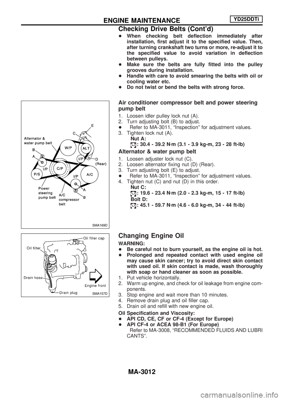
Air conditioner compressor belt and power steering
pump belt
1. Loosen idler pulley lock nut (A).
2. Turn adjusting bolt (B) to adjust.
+Refer to MA-3011, ªInspectionº for adjustment values.
3. Tighten lock nut (A).
Nut A:
: 30.4 - 39.2 Nzm (3.1 - 3.9 kg-m, 23 - 28 ft-lb)
Alternator & water pump belt
1. Loosen adjuster lock nut (C).
2. Loosen alternator fixing nut (D) (Rear).
3. Turn adjusting bolt (E) to adjust.
+Refer to MA-3011, ªInspectionº for adjustment values.
4. Tighten nut (C) and nut (D) in this order.
Nut C:
: 19.6 - 23.4 Nzm (2.0 - 2.3 kg-m, 15 - 17 ft-lb)
Bolt D:
: 45.1 - 59.7 Nzm (4.6 - 6.0 kg-m, 34 - 44 ft-lb)
Changing Engine Oil
WARNING:
+Be careful not to burn yourself, as the engine oil is hot.
+Prolonged and repeated contact with used engine oil
may cause skin cancer; try to avoid direct skin contact
with used oil. If skin contact is made, wash thoroughly
with soap or hand cleaner as soon as possible.
1. Put vehicle horizontally.
2. Warm up engine, and check for oil leakage from engine com-
ponents.
3. Stop engine and wait more than 10 minutes.
4. Remove drain plug and oil filler cap.
5. Drain oil and refill with new engine oil.
Oil Specification and Viscosity:
+API CD, CE, CF or CF-4 (Except for Europe)
+API CF-4 or ACEA 98-B1 (For Europe)
Refer to MA-3008, ªRECOMMENDED FLUIDS AND LUBRI
CANTSº.
SMA169D
SMA157D
ENGINE MAINTENANCEYD25DDTi
Checking Drive Belts (Cont'd)
MA-3012
Page 1042 of 1306
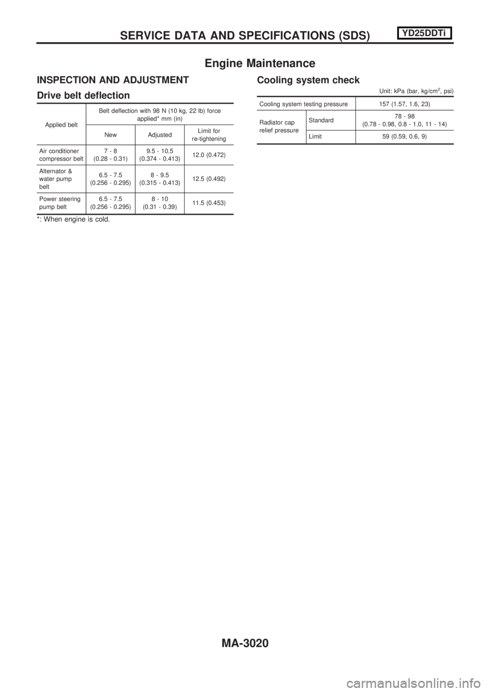
Engine Maintenance
INSPECTION AND ADJUSTMENT
Drive belt deflection
Applied beltBelt deflection with 98 N (10 kg, 22 lb) force
applied* mm (in)
New Adjusted Limit for
re-tightening
Air conditioner
compressor belt 7-8
(0.28 - 0.31) 9.5 - 10.5
(0.374 - 0.413) 12.0 (0.472)
Alternator &
water pump
belt 6.5 - 7.5
(0.256 - 0.295) 8 - 9.5
(0.315 - 0.413) 12.5 (0.492)
Power steering
pump belt 6.5 - 7.5
(0.256 - 0.295) 8-10
(0.31 - 0.39) 11.5 (0.453)
*: When engine is cold.
Cooling system check
Unit: kPa (bar, kg/cm2, psi)
Cooling system testing pressure 157 (1.57, 1.6, 23)
Radiator cap
relief pressureStandard
78-98
(0.78 - 0.98, 0.8 - 1.0, 11 - 14)
Limit 59 (0.59, 0.6, 9)
SERVICEDATAANDSPECIFICATIONS(SDS) YD25DDTi
MA-3020
Page 1064 of 1306
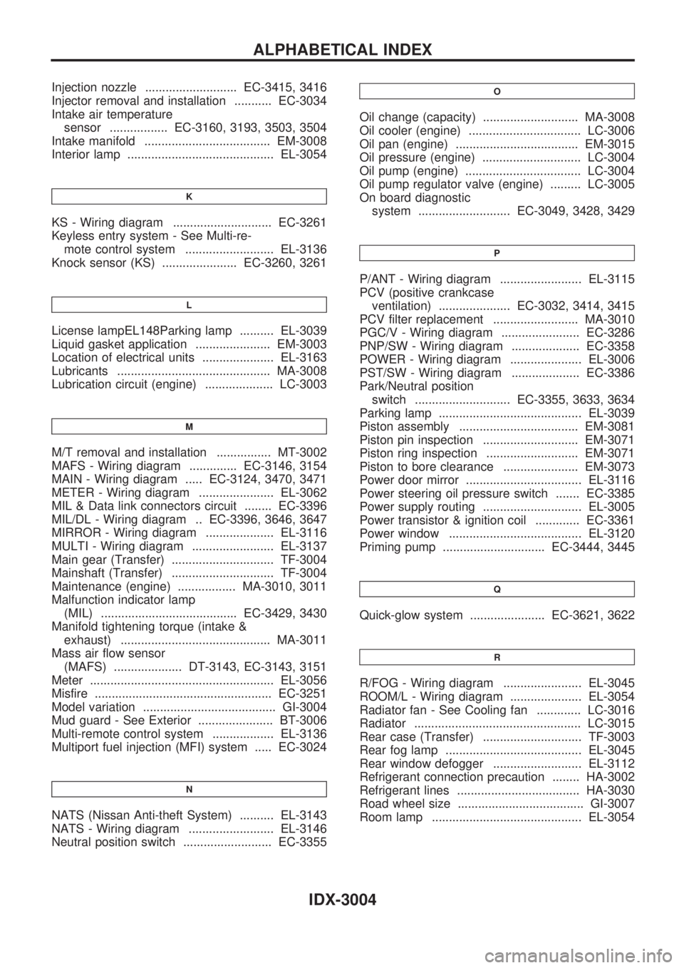
Injection nozzle ........................... EC-3415, 3416
Injector removal and installation ........... EC-3034
Intake air temperature
sensor ................. EC-3160, 3193, 3503, 3504
Intake manifold ..................................... EM-3008
Interior lamp ........................................... EL-3054
K
KS - Wiring diagram ............................. EC-3261
Keyless entry system - See Multi-re-
mote control system .......................... EL-3136
Knock sensor (KS) ...................... EC-3260, 3261
L
License lampEL148Parking lamp .......... EL-3039
Liquid gasket application ...................... EM-3003
Location of electrical units ..................... EL-3163
Lubricants ............................................. MA-3008
Lubrication circuit (engine) .................... LC-3003
M
M/T removal and installation ................ MT-3002
MAFS - Wiring diagram .............. EC-3146, 3154
MAIN - Wiring diagram ..... EC-3124, 3470, 3471
METER - Wiring diagram ...................... EL-3062
MIL & Data link connectors circuit ........ EC-3396
MIL/DL - Wiring diagram .. EC-3396, 3646, 3647
MIRROR - Wiring diagram .................... EL-3116
MULTI - Wiring diagram ........................ EL-3137
Main gear (Transfer) .............................. TF-3004
Mainshaft (Transfer) .............................. TF-3004
Maintenance (engine) ................. MA-3010, 3011
Malfunction indicator lamp
(MIL) ........................................ EC-3429, 3430
Manifold tightening torque (intake &
exhaust) ............................................ MA-3011
Mass air flow sensor
(MAFS) .................... DT-3143, EC-3143, 3151
Meter ...................................................... EL-3056
Misfire .................................................... EC-3251
Model variation ....................................... GI-3004
Mud guard - See Exterior ...................... BT-3006
Multi-remote control system .................. EL-3136
Multiport fuel injection (MFI) system ..... EC-3024
N
NATS (Nissan Anti-theft System) .......... EL-3143
NATS - Wiring diagram ......................... EL-3146
Neutral position switch .......................... EC-3355
O
Oil change (capacity) ............................ MA-3008
Oil cooler (engine) ................................. LC-3006
Oil pan (engine) .................................... EM-3015
Oil pressure (engine) ............................. LC-3004
Oil pump (engine) .................................. LC-3004
Oil pump regulator valve (engine) ......... LC-3005
On board diagnostic
system ........................... EC-3049, 3428, 3429
P
P/ANT - Wiring diagram ........................ EL-3115
PCV (positive crankcase
ventilation) ..................... EC-3032, 3414, 3415
PCV filter replacement ......................... MA-3010
PGC/V - Wiring diagram ....................... EC-3286
PNP/SW - Wiring diagram .................... EC-3358
POWER - Wiring diagram ..................... EL-3006
PST/SW - Wiring diagram .................... EC-3386
Park/Neutral position
switch ............................ EC-3355, 3633, 3634
Parking lamp .......................................... EL-3039
Piston assembly ................................... EM-3081
Piston pin inspection ............................ EM-3071
Piston ring inspection ........................... EM-3071
Piston to bore clearance ...................... EM-3073
Power door mirror .................................. EL-3116
Power steering oil pressure switch ....... EC-3385
Power supply routing ............................. EL-3005
Power transistor & ignition coil ............. EC-3361
Power window ....................................... EL-3120
Priming pump .............................. EC-3444, 3445
Q
Quick-glow system ...................... EC-3621, 3622
R
R/FOG - Wiring diagram ....................... EL-3045
ROOM/L - Wiring diagram ..................... EL-3054
Radiator fan - See Cooling fan ............. LC-3016
Radiator ................................................. LC-3015
Rear case (Transfer) ............................. TF-3003
Rear fog lamp ........................................ EL-3045
Rear window defogger .......................... EL-3112
Refrigerant connection precaution ........ HA-3002
Refrigerant lines .................................... HA-3030
Road wheel size ..................................... GI-3007
Room lamp ............................................ EL-3054
ALPHABETICAL INDEX
IDX-3004
Page 1133 of 1306
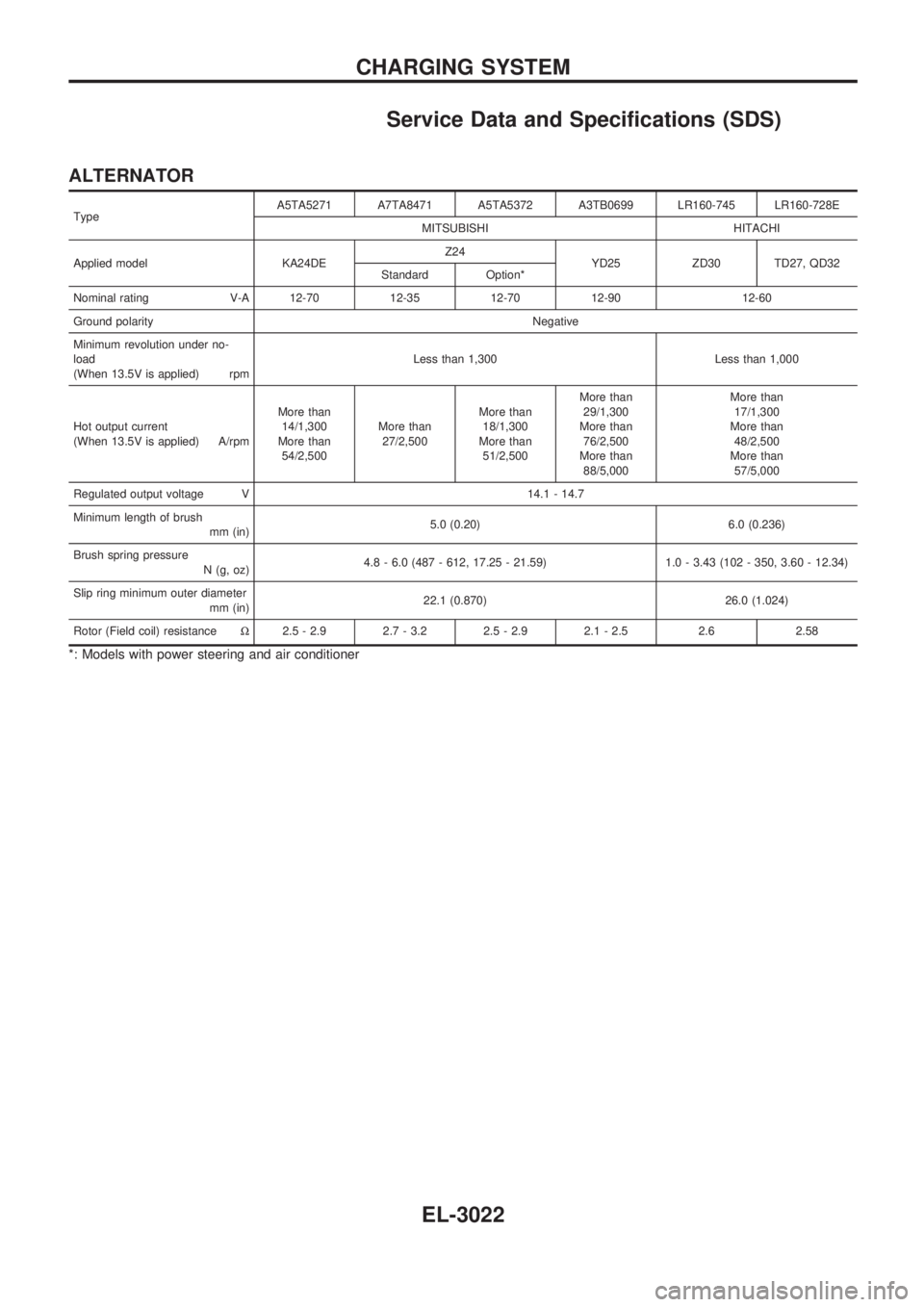
Service Data and Specifications (SDS)
ALTERNATOR
TypeA5TA5271 A7TA8471 A5TA5372 A3TB0699 LR160-745 LR160-728E
MITSUBISHI HITACHI
Applied model KA24DEZ24
YD25 ZD30 TD27, QD32
Standard Option*
Nominal rating V-A 12-70 12-35 12-70 12-90 12-60
Ground polarityNegative
Minimum revolution under no-
load
(When 13.5V is applied) rpmLess than 1,300 Less than 1,000
Hot output current
(When 13.5V is applied) A/rpmMore than
14/1,300
More than
54/2,500More than
27/2,500More than
18/1,300
More than
51/2,500More than
29/1,300
More than
76/2,500
More than
88/5,000More than
17/1,300
More than
48/2,500
More than
57/5,000
Regulated output voltage V 14.1 - 14.7
Minimum length of brush
mm (in)5.0 (0.20) 6.0 (0.236)
Brush spring pressure
N (g, oz)4.8 - 6.0 (487 - 612, 17.25 - 21.59) 1.0 - 3.43 (102 - 350, 3.60 - 12.34)
Slip ring minimum outer diameter
mm (in)22.1 (0.870) 26.0 (1.024)
Rotor (Field coil) resistanceW2.5 - 2.9 2.7 - 3.2 2.5 - 2.9 2.1 - 2.5 2.6 2.58
*: Models with power steering and air conditioner
CHARGING SYSTEM
EL-3022
Page 1306 of 1306
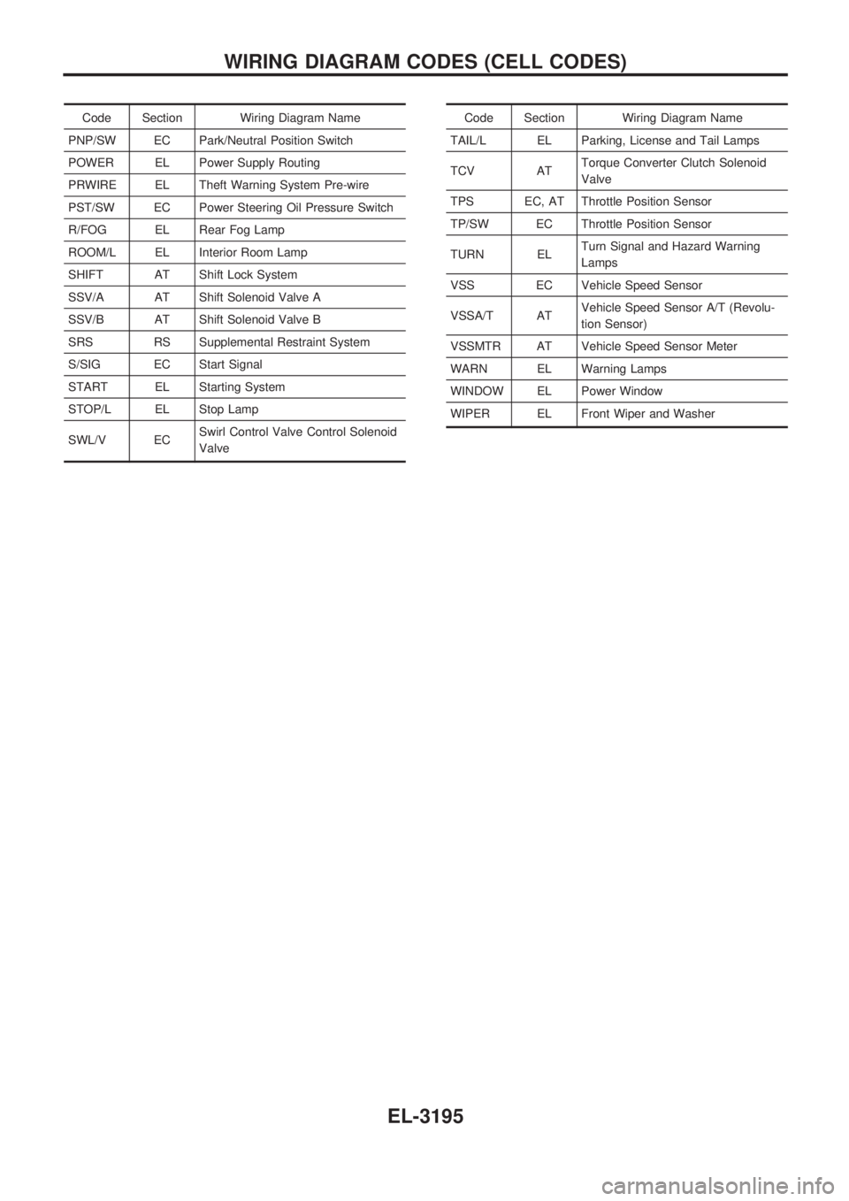
Code Section Wiring Diagram Name
PNP/SW EC Park/Neutral Position Switch
POWER EL Power Supply Routing
PRWIRE EL Theft Warning System Pre-wire
PST/SW EC Power Steering Oil Pressure Switch
R/FOG EL Rear Fog Lamp
ROOM/L EL Interior Room Lamp
SHIFT AT Shift Lock System
SSV/A AT Shift Solenoid Valve A
SSV/B AT Shift Solenoid Valve B
SRS RS Supplemental Restraint System
S/SIG EC Start Signal
START EL Starting System
STOP/L EL Stop Lamp
SWL/V ECSwirl Control Valve Control Solenoid
ValveCode Section Wiring Diagram Name
TAIL/L EL Parking, License and Tail Lamps
TCV ATTorque Converter Clutch Solenoid
Valve
TPS EC, AT Throttle Position Sensor
TP/SW EC Throttle Position Sensor
TURN ELTurn Signal and Hazard Warning
Lamps
VSS EC Vehicle Speed Sensor
VSSA/T ATVehicle Speed Sensor A/T (Revolu-
tion Sensor)
VSSMTR AT Vehicle Speed Sensor Meter
WARN EL Warning Lamps
WINDOW EL Power Window
WIPER EL Front Wiper and Washer
WIRING DIAGRAM CODES (CELL CODES)
EL-3195