2001 NISSAN PICK-UP oil type
[x] Cancel search: oil typePage 441 of 1306
Installation
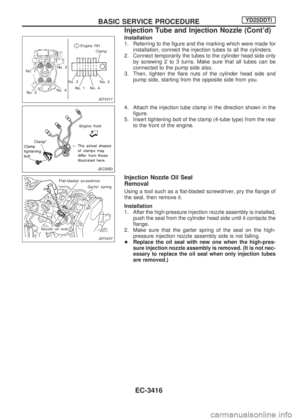
1. Referring to the figure and the marking which were made for
installation, connect the injection tubes to all the cylinders.
2. Connect temporarily the tubes to the cylinder head side only
by screwing 2 to 3 turns. Make sure that all tubes can be
connected to the pump side also.
3. Then, tighten the flare nuts of the cylinder head side and
pump side, starting from the opposite side from you.
4. Attach the injection tube clamp in the direction shown in the
figure.
5. Insert tightening bolt of the clamp (4-tube type) from the rear
to the front of the engine.
Injection Nozzle Oil Seal
Removal
Using a tool such as a flat-bladed screwdriver, pry the flange of
the seal, then remove it.
Installation
1. After the high-pressure injection nozzle assembly is installed,
push the seal from the cylinder head side until it contacts the
flange.
2. Make sure that the garter spring of the seal on the high-
pressure injection nozzle assembly side is not falling.
+Replace the oil seal with new one when the high-pres-
sure injection nozzle assembly is removed. (It is not nec-
essary to replace the oil seal when only injection tubes
are removed.)
JEF341Y
JEC335D
JEF343Y
BASIC SERVICE PROCEDUREYD25DDTi
Injection Tube and Injection Nozzle (Cont'd)
EC-3416
Page 697 of 1306
Service Data and Specifications (SDS)
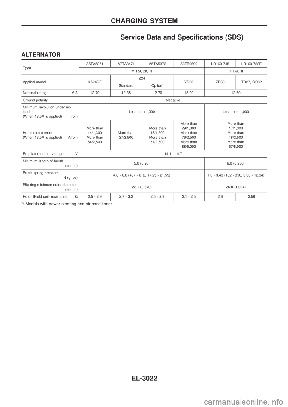
ALTERNATOR
TypeA5TA5271 A7TA8471 A5TA5372 A3TB0699 LR160-745 LR160-728E
MITSUBISHI HITACHI
Applied model KA24DEZ24
YD25 ZD30 TD27, QD32
Standard Option*
Nominal rating V-A 12-70 12-35 12-70 12-90 12-60
Ground polarityNegative
Minimum revolution under no-
load
(When 13.5V is applied) rpmLess than 1,300 Less than 1,000
Hot output current
(When 13.5V is applied) A/rpmMore than
14/1,300
More than
54/2,500More than
27/2,500More than
18/1,300
More than
51/2,500More than
29/1,300
More than
76/2,500
More than
88/5,000More than
17/1,300
More than
48/2,500
More than
57/5,000
Regulated output voltage V 14.1 - 14.7
Minimum length of brush
mm (in)5.0 (0.20) 6.0 (0.236)
Brush spring pressure
N (g, oz)4.8 - 6.0 (487 - 612, 17.25 - 21.59) 1.0 - 3.43 (102 - 350, 3.60 - 12.34)
Slip ring minimum outer diameter
mm (in)22.1 (0.870) 26.0 (1.024)
Rotor (Field coil) resistanceW2.5 - 2.9 2.7 - 3.2 2.5 - 2.9 2.1 - 2.5 2.6 2.58
*: Models with power steering and air conditioner
CHARGING SYSTEM
EL-3022
Page 702 of 1306
Bulb Replacement
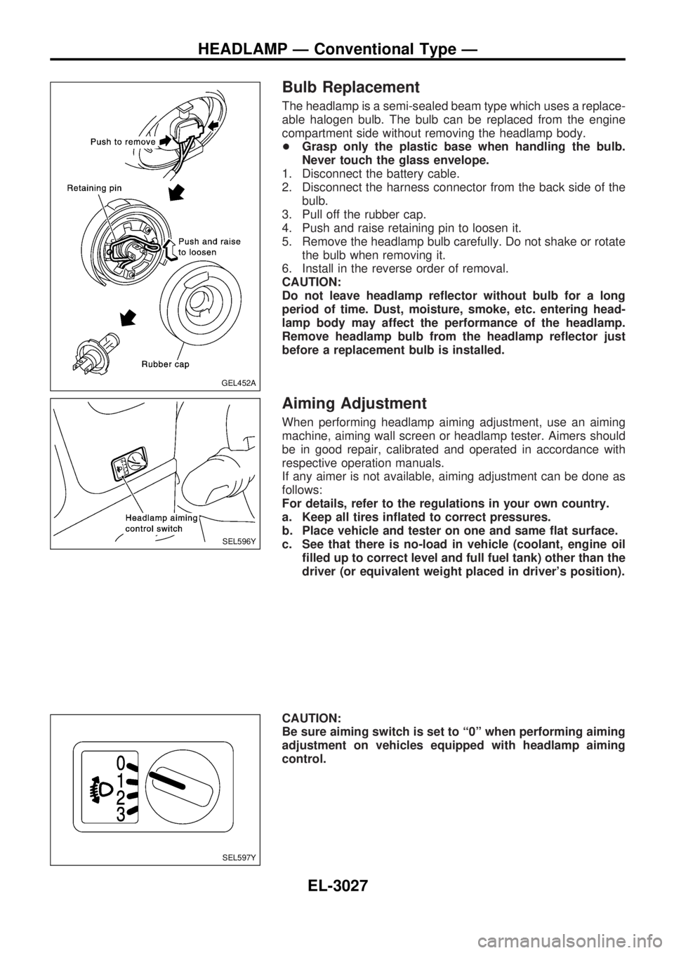
The headlamp is a semi-sealed beam type which uses a replace-
able halogen bulb. The bulb can be replaced from the engine
compartment side without removing the headlamp body.
+Grasp only the plastic base when handling the bulb.
Never touch the glass envelope.
1. Disconnect the battery cable.
2. Disconnect the harness connector from the back side of the
bulb.
3. Pull off the rubber cap.
4. Push and raise retaining pin to loosen it.
5. Remove the headlamp bulb carefully. Do not shake or rotate
the bulb when removing it.
6. Install in the reverse order of removal.
CAUTION:
Do not leave headlamp reflector without bulb for a long
period of time. Dust, moisture, smoke, etc. entering head-
lamp body may affect the performance of the headlamp.
Remove headlamp bulb from the headlamp reflector just
before a replacement bulb is installed.
Aiming Adjustment
When performing headlamp aiming adjustment, use an aiming
machine, aiming wall screen or headlamp tester. Aimers should
be in good repair, calibrated and operated in accordance with
respective operation manuals.
If any aimer is not available, aiming adjustment can be done as
follows:
For details, refer to the regulations in your own country.
a. Keep all tires inflated to correct pressures.
b. Place vehicle and tester on one and same flat surface.
c. See that there is no-load in vehicle (coolant, engine oil
filled up to correct level and full fuel tank) other than the
driver (or equivalent weight placed in driver's position).
CAUTION:
Be sure aiming switch is set to ª0º when performing aiming
adjustment on vehicles equipped with headlamp aiming
control.
GEL452A
SEL596Y
SEL597Y
HEADLAMP Ð Conventional Type Ð
EL-3027
Page 889 of 1306
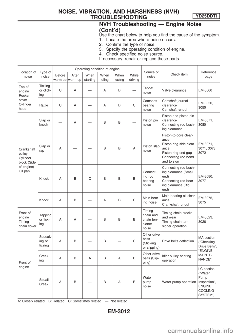
Use the chart below to help you find the cause of the symptom.
1. Locate the area where noise occurs.
2. Confirm the type of noise.
3. Specify the operating condition of engine.
4. Check specified noise source.
If necessary, repair or replace these parts.
Location of
noiseType of
noiseOperating condition of engine
Source of
noiseCheck itemReference
page Before
warm-upAfter
warm-upWhen
startingWhen
idlingWhen
racingWhile
driving
Top of
engine
Rocker
cover
Cylinder
headTicking
or click-
ingCAÐABÐTappet
noiseValve clearance EM-3060
Rattle C A Ð A B CCamshaft
bearing
noiseCamshaft journal
clearance
Camshaft runoutEM-3050,
3050
Crankshaft
pulley
Cylinder
block (Side
of engine)
Oil panSlap or
knockÐAÐB BÐPiston pin
noisePiston and piston pin
clearance
Connecting rod bush-
ing clearanceEM-3071,
3080
Slap or
rapAÐÐBBAPiston slap
noisePiston-to-bore clear-
ance
Piston ring side clear-
ance
Piston ring end gap
Connecting rod bend
and torsionEM-3071,
3071, 3073,
3072
Knock A B C B B BConnect-
ing rod
bearing
noiseConnecting rod bush-
ing clearance (Small
end)
Connecting rod bear-
ing clearance (Big
end)EM-3080,
3077
Knock A B Ð A B CMain bear-
ing noiseMain bearing oil clear-
ance
Crankshaft runoutEM-3075,
3075
Front of
engine
Timing
chain coverTapping
or tick-
ingAAÐBBBTiming
chain and
chain ten-
sioner
noiseTiming chain cracks
and wear
Timing chain ten-
sioner operationEM-3023,
3026
Front of
engineSqueak-
ing or
fizzingABÐBÐCOther drive
belts
(Sticking
or slipping)Drive belts deflectionMA section
(ªChecking
Drive Beltsº,
ªENGINE
MAINTE-
NANCEº) Creak-
ingABABABOther drive
belts (Slip-
ping)Idler pulley bearing
operation
Squall
CreakABÐBABWater
pump
noiseWater pump operationLC section
(ªWater
Pump
Inspectionº,
ENGINE
COOLING
SYSTEMº)
A: Closely related B: Related C: Sometimes related Ð: Not related
NOISE, VIBRATION, AND HARSHNESS (NVH)
TROUBLESHOOTINGYD25DDTi
NVH Troubleshooting Ð Engine Noise
(Cont'd)
EM-3012
Page 905 of 1306
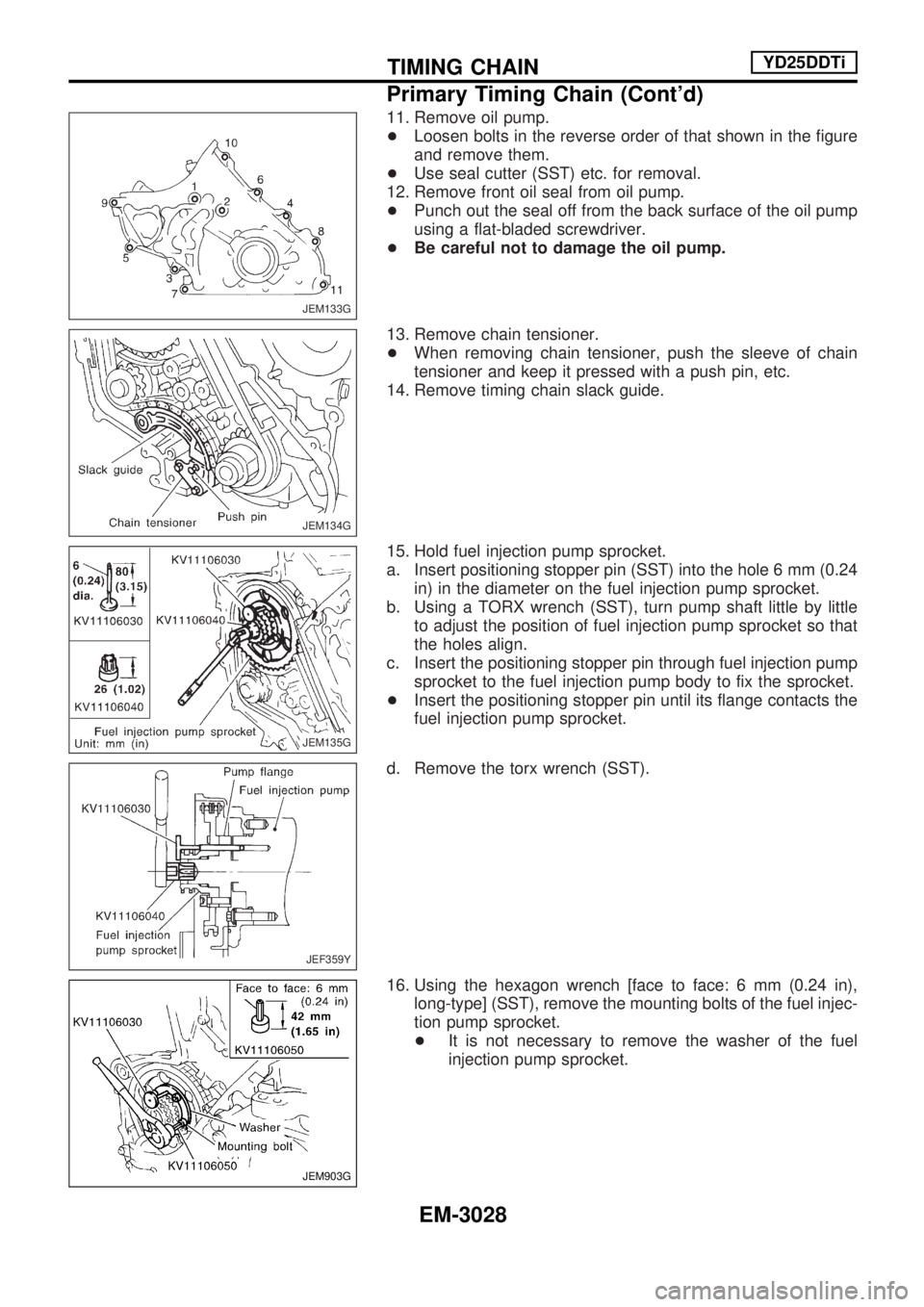
11. Remove oil pump.
+Loosen bolts in the reverse order of that shown in the figure
and remove them.
+Use seal cutter (SST) etc. for removal.
12. Remove front oil seal from oil pump.
+Punch out the seal off from the back surface of the oil pump
using a flat-bladed screwdriver.
+Be careful not to damage the oil pump.
13. Remove chain tensioner.
+When removing chain tensioner, push the sleeve of chain
tensioner and keep it pressed with a push pin, etc.
14. Remove timing chain slack guide.
15. Hold fuel injection pump sprocket.
a. Insert positioning stopper pin (SST) into the hole 6 mm (0.24
in) in the diameter on the fuel injection pump sprocket.
b. Using a TORX wrench (SST), turn pump shaft little by little
to adjust the position of fuel injection pump sprocket so that
the holes align.
c. Insert the positioning stopper pin through fuel injection pump
sprocket to the fuel injection pump body to fix the sprocket.
+Insert the positioning stopper pin until its flange contacts the
fuel injection pump sprocket.
d. Remove the torx wrench (SST).
16. Using the hexagon wrench [face to face: 6 mm (0.24 in),
long-type] (SST), remove the mounting bolts of the fuel injec-
tion pump sprocket.
+It is not necessary to remove the washer of the fuel
injection pump sprocket.
JEM133G
JEM134G
JEM135G
JEF359Y
JEM903G
TIMING CHAINYD25DDTi
Primary Timing Chain (Cont'd)
EM-3028
Page 908 of 1306
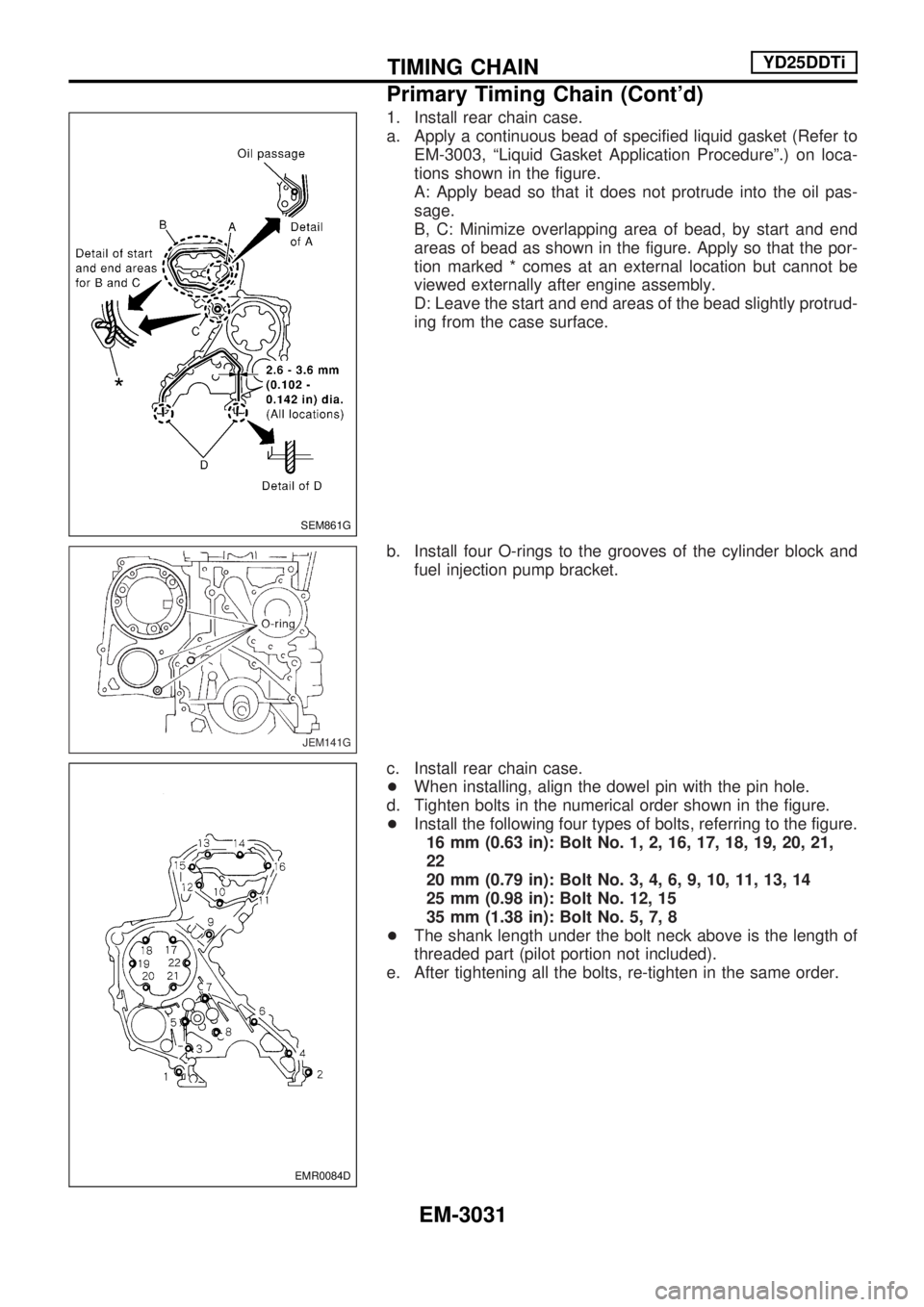
1. Install rear chain case.
a. Apply a continuous bead of specified liquid gasket (Refer to
EM-3003, ªLiquid Gasket Application Procedureº.) on loca-
tions shown in the figure.
A: Apply bead so that it does not protrude into the oil pas-
sage.
B, C: Minimize overlapping area of bead, by start and end
areas of bead as shown in the figure. Apply so that the por-
tion marked * comes at an external location but cannot be
viewed externally after engine assembly.
D: Leave the start and end areas of the bead slightly protrud-
ing from the case surface.
b. Install four O-rings to the grooves of the cylinder block and
fuel injection pump bracket.
c. Install rear chain case.
+When installing, align the dowel pin with the pin hole.
d. Tighten bolts in the numerical order shown in the figure.
+Install the following four types of bolts, referring to the figure.
16 mm (0.63 in): Bolt No. 1, 2, 16, 17, 18, 19, 20, 21,
22
20 mm (0.79 in): Bolt No. 3, 4, 6, 9, 10, 11, 13, 14
25 mm (0.98 in): Bolt No. 12, 15
35 mm (1.38 in): Bolt No. 5, 7, 8
+The shank length under the bolt neck above is the length of
threaded part (pilot portion not included).
e. After tightening all the bolts, re-tighten in the same order.
SEM861G
JEM141G
EMR0084D
TIMING CHAINYD25DDTi
Primary Timing Chain (Cont'd)
EM-3031
Page 1022 of 1306
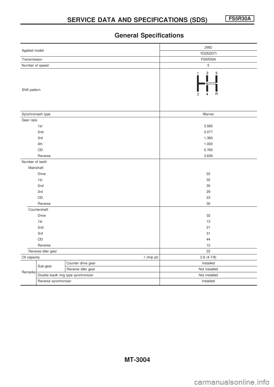
General Specifications
Applied model2WD
YD25DDTi
TransmissionFS5R30A
Number of speed5
Shift pattern
Synchromesh typeWarner
Gear ratio
1st3.580
2nd2.077
3rd1.360
4th1.000
OD0.760
Reverse3.636
Number of teeth
Mainshaft
Drive22
1st32
2nd30
3rd29
OD23
Reverse30
Countershaft
Drive32
1st13
2nd21
3rd31
OD44
Reverse12
Reverse idler gear22
Oil capacity!(lmp pt) 2.8 (4-7/8)
RemarksSub-gearCounter drive gear Installed
Reverse idler gear Not installed
Double baulk ring type synchronizer Not installed
Reverse synchronizerInstalled
SERVICE DATA AND SPECIFICATIONS (SDS)FS5R30A
MT-3004
Page 1024 of 1306
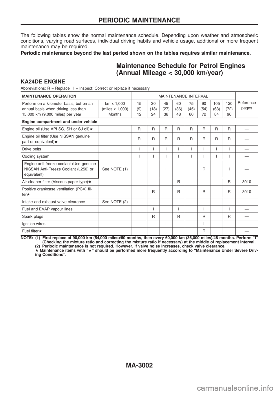
The following tables show the normal maintenance schedule. Depending upon weather and atmospheric
conditions, varying road surfaces, individual driving habits and vehicle usage, additional or more frequent
maintenance may be required.
Periodic maintenance beyond the last period shown on the tables requires similar maintenance.
Maintenance Schedule for Petrol Engines
(Annual Mileage < 30,000 km/year)
KA24DE ENGINE
Abbreviations: R = Replace I = Inspect: Correct or replace if necessary
MAINTENANCE OPERATIONMAINTENANCE INTERVAL
Reference
pages Perform on a kilometer basis, but on an
annual basis when driving less than
15,000 km (9,000 miles) per yearkm x 1,000
(miles x 1,000)
Months15
(9)
1230
(18)
2445
(27)
3660
(36)
4875
(45)
6090
(54)
72105
(63)
84120
(72)
96
Engine compartment and under vehicle
Engine oil (Use API SG, SH or SJ oil)HR RRRRRRR Ð
Engine oil filter (Use NISSAN genuine
part or equivalent)HR RRRRRRR Ð
Drive belts IIIIIIII Ð
Cooling system IIIIIIII Ð
Engine anti-freeze coolant (Use genuine
NISSAN Anti-Freeze Coolant (L250) or
equivalent)See NOTE (1) I R I Ð
Air cleaner filter (Viscous paper type)HR R 3010
Positive crankcase ventilation (PCV) fil-
terHRRRR3010
Intake and exhaust valve clearance See NOTE (2) Ð
Fuel and EVAP vapour linesIIIIÐ
Spark plugsRRRRÐ
Ignition wires I I Ð
Fuel filterHRÐ
NOTE: (1) First replace at 90,000 km (54,000 miles)/60 months, then every 60,000 km (36,000 miles)/48 months. Perform ªIº
(Checking the mixture ratio and correcting the mixture ratio if necessary) at the middle of replacement interval.
(2) Periodic maintenance is not required. However, if valve noise increases, check valve clearance.
HMaintenance items with ªHº should be performed more frequently according to ªMaintenance Under Severe Driv-
ing Conditionsº.
PERIODIC MAINTENANCE
MA-3002