2001 NISSAN PICK-UP clutch
[x] Cancel search: clutchPage 1 of 1306

GENERAL INFORMATIONGI
MAINTENANCEMA
ENGINE MECHANICALEM
ENGINE LUBRICATION &
COOLING SYSTEMSLC
ENGINE CONTROL SYSTEMEC
ACCELERATOR CONTROL, FUEL &
EXHAUST SYSTEMSFE
CLUTCHCL
MANUAL TRANSAXLEMT
TRANSFERTF
PROPELLER SHAFT &
DIFFERENTIAL CARRIERPD
FRONT AXLE & FRONT SUSPENSIONFA
REAR AXLE & REAR SUSPENSIONRA
BRAKE SYSTEMBR
STEERING SYSTEMST
RESTRAINT SYSTEMRS
BODY & TRIMBT
HEATER & AIR CONDITIONERHA
ELECTRICAL SYSTEMEL
ALPHABETICAL INDEXIDX
PICKUP
MODEL D22 SERIES
FOREWORD
This supplement contains informa-
tion concerning necessary service
procedures and relevant data for the
model D22 series.
All information, illustrations and spe-
ci®cations contained in this supple-
ment are based on the latest product
information available at the time of
publication. If your NISSAN model
differs from the speci®cations contain-
ed in this supplement, consult your
NISSAN distributor for information.
The right is reserved to make chan-
ges in speci®cations and methods at
any time without notice.
Edition: November 2001
Printing: November 2001 (01)
Publication No.: SM1E-D22CE0E
NISSAN EUROPE S.A.S.
2001 NISSAN EUROPE S.A.S. Printed in the Netherlands
Not to be reproduced in whole or in part without the prior written permission of Nissan Europe S.A.S., Paris, France.
QUICK REFERENCE INDEX
Page 3 of 1306
CLUTCH
SECTION
CL
MODIFICATION NOTICE:
YD25DDTi engine model has been added.
CONTENTS
SERVICE DATA AND SPECIFICATIONS
(SDS).................................................................... 3002
General Specifications ..................................... 3002
Inspection and Adjustment .............................. 3002
CL
Page 4 of 1306
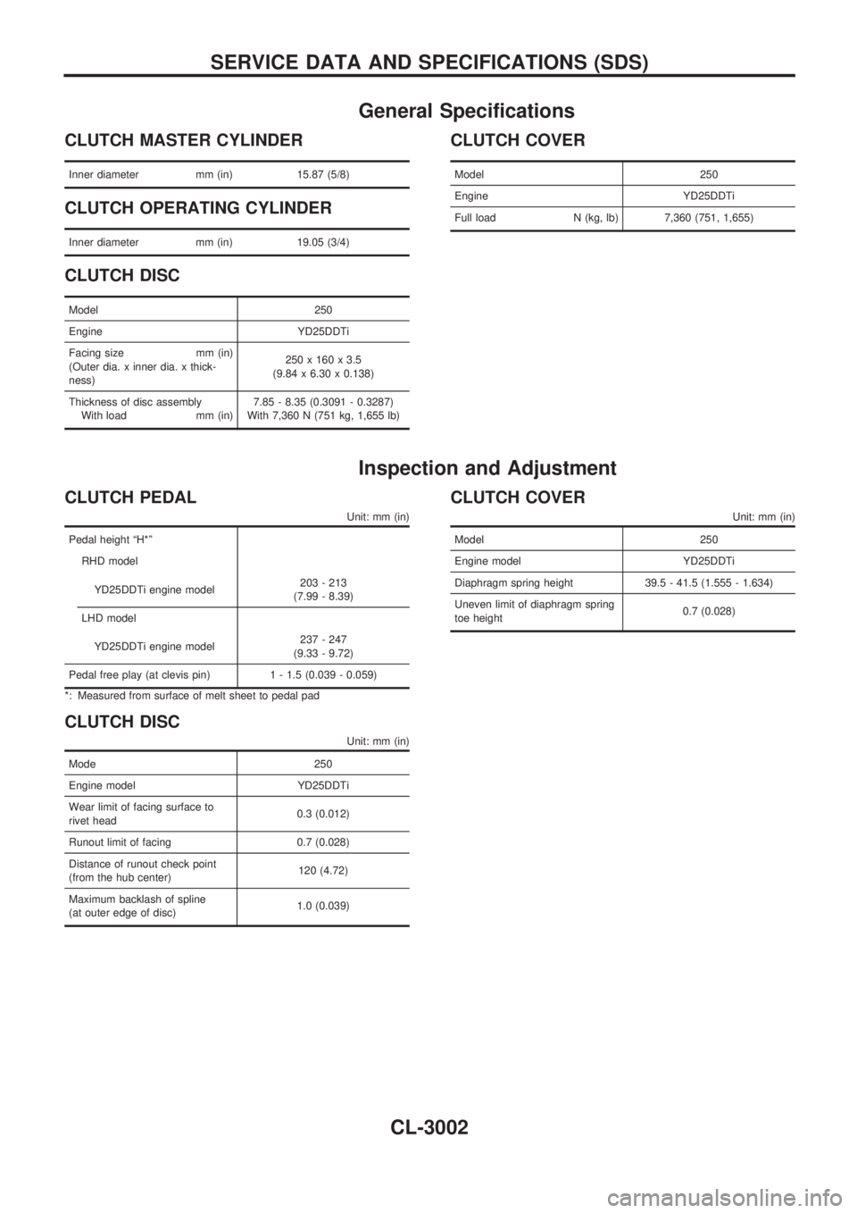
General Specifications
CLUTCH MASTER CYLINDER
Inner diameter mm (in) 15.87 (5/8)
CLUTCH OPERATING CYLINDER
Inner diameter mm (in) 19.05 (3/4)
CLUTCH DISC
Model 250
Engine YD25DDTi
Facing size mm (in)
(Outer dia. x inner dia. x thick-
ness)250 x 160 x 3.5
(9.84 x 6.30 x 0.138)
Thickness of disc assembly
With load mm (in)7.85 - 8.35 (0.3091 - 0.3287)
With 7,360 N (751 kg, 1,655 lb)
CLUTCH COVER
Model 250
Engine YD25DDTi
Full load N (kg, lb) 7,360 (751, 1,655)
Inspection and Adjustment
CLUTCH PEDAL
Unit: mm (in)
Pedal height ªH*º
RHD model
YD25DDTi engine model203 - 213
(7.99 - 8.39)
LHD model
YD25DDTi engine model237 - 247
(9.33 - 9.72)
Pedal free play (at clevis pin) 1 - 1.5 (0.039 - 0.059)
*: Measured from surface of melt sheet to pedal pad
CLUTCH DISC
Unit: mm (in)
Mode 250
Engine model YD25DDTi
Wear limit of facing surface to
rivet head0.3 (0.012)
Runout limit of facing 0.7 (0.028)
Distance of runout check point
(from the hub center)120 (4.72)
Maximum backlash of spline
(at outer edge of disc)1.0 (0.039)
CLUTCH COVER
Unit: mm (in)
Model 250
Engine model YD25DDTi
Diaphragm spring height 39.5 - 41.5 (1.555 - 1.634)
Uneven limit of diaphragm spring
toe height0.7 (0.028)
SERVICE DATA AND SPECIFICATIONS (SDS)
CL-3002
Page 869 of 1306
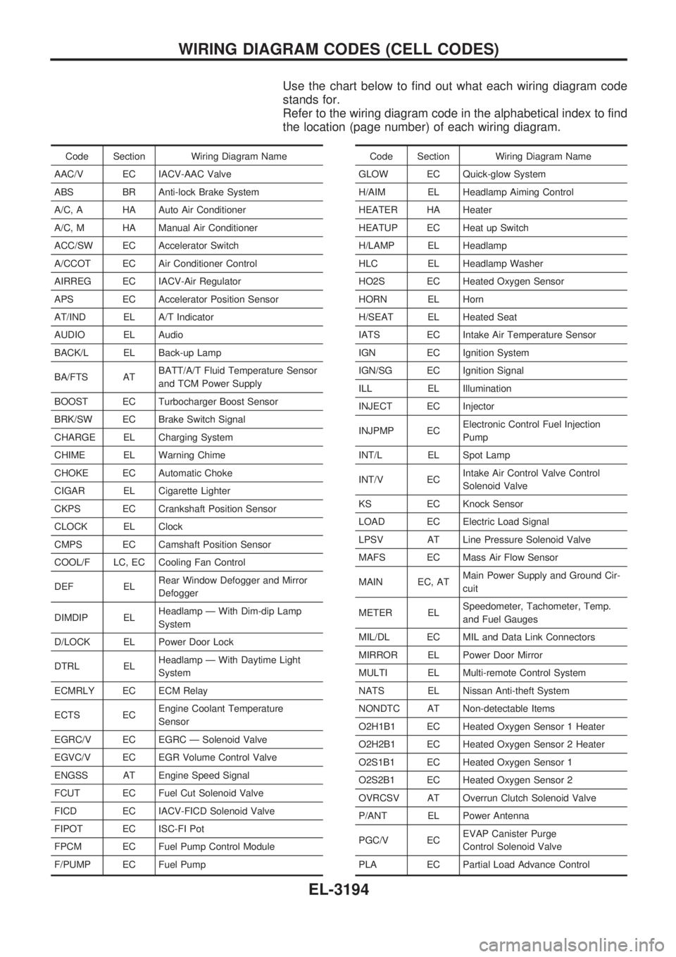
Use the chart below to find out what each wiring diagram code
stands for.
Refer to the wiring diagram code in the alphabetical index to find
the location (page number) of each wiring diagram.
Code Section Wiring Diagram Name
AAC/V EC IACV-AAC Valve
ABS BR Anti-lock Brake System
A/C, A HA Auto Air Conditioner
A/C, M HA Manual Air Conditioner
ACC/SW EC Accelerator Switch
A/CCOT EC Air Conditioner Control
AIRREG EC IACV-Air Regulator
APS EC Accelerator Position Sensor
AT/IND EL A/T Indicator
AUDIO EL Audio
BACK/L EL Back-up Lamp
BA/FTS ATBATT/A/T Fluid Temperature Sensor
and TCM Power Supply
BOOST EC Turbocharger Boost Sensor
BRK/SW EC Brake Switch Signal
CHARGE EL Charging System
CHIME EL Warning Chime
CHOKE EC Automatic Choke
CIGAR EL Cigarette Lighter
CKPS EC Crankshaft Position Sensor
CLOCK EL Clock
CMPS EC Camshaft Position Sensor
COOL/F LC, EC Cooling Fan Control
DEF ELRear Window Defogger and Mirror
Defogger
DIMDIP ELHeadlamp Ð With Dim-dip Lamp
System
D/LOCK EL Power Door Lock
DTRL ELHeadlamp Ð With Daytime Light
System
ECMRLY EC ECM Relay
ECTS ECEngine Coolant Temperature
Sensor
EGRC/V EC EGRC Ð Solenoid Valve
EGVC/V EC EGR Volume Control Valve
ENGSS AT Engine Speed Signal
FCUT EC Fuel Cut Solenoid Valve
FICD EC IACV-FICD Solenoid Valve
FIPOT EC ISC-FI Pot
FPCM EC Fuel Pump Control Module
F/PUMP EC Fuel PumpCode Section Wiring Diagram Name
GLOW EC Quick-glow System
H/AIM EL Headlamp Aiming Control
HEATER HA Heater
HEATUP EC Heat up Switch
H/LAMP EL Headlamp
HLC EL Headlamp Washer
HO2S EC Heated Oxygen Sensor
HORN EL Horn
H/SEAT EL Heated Seat
IATS EC Intake Air Temperature Sensor
IGN EC Ignition System
IGN/SG EC Ignition Signal
ILL EL Illumination
INJECT EC Injector
INJPMP ECElectronic Control Fuel Injection
Pump
INT/L EL Spot Lamp
INT/V ECIntake Air Control Valve Control
Solenoid Valve
KS EC Knock Sensor
LOAD EC Electric Load Signal
LPSV AT Line Pressure Solenoid Valve
MAFS EC Mass Air Flow Sensor
MAIN EC, ATMain Power Supply and Ground Cir-
cuit
METER ELSpeedometer, Tachometer, Temp.
and Fuel Gauges
MIL/DL EC MIL and Data Link Connectors
MIRROR EL Power Door Mirror
MULTI EL Multi-remote Control System
NATS EL Nissan Anti-theft System
NONDTC AT Non-detectable Items
O2H1B1 EC Heated Oxygen Sensor 1 Heater
O2H2B1 EC Heated Oxygen Sensor 2 Heater
O2S1B1 EC Heated Oxygen Sensor 1
O2S2B1 EC Heated Oxygen Sensor 2
OVRCSV AT Overrun Clutch Solenoid Valve
P/ANT EL Power Antenna
PGC/V ECEVAP Canister Purge
Control Solenoid Valve
PLA EC Partial Load Advance Control
WIRING DIAGRAM CODES (CELL CODES)
EL-3194
Page 870 of 1306
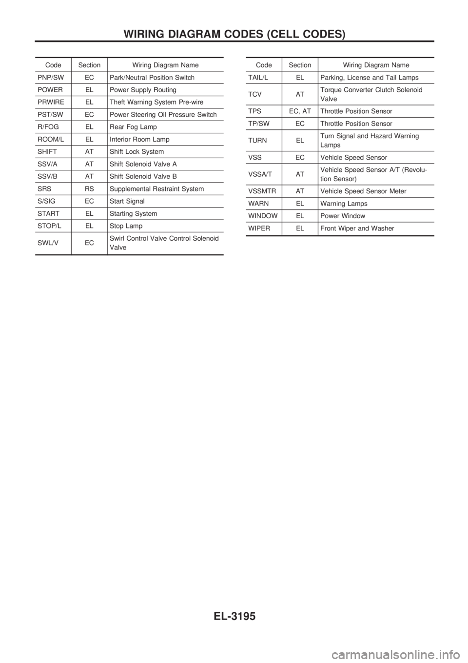
Code Section Wiring Diagram Name
PNP/SW EC Park/Neutral Position Switch
POWER EL Power Supply Routing
PRWIRE EL Theft Warning System Pre-wire
PST/SW EC Power Steering Oil Pressure Switch
R/FOG EL Rear Fog Lamp
ROOM/L EL Interior Room Lamp
SHIFT AT Shift Lock System
SSV/A AT Shift Solenoid Valve A
SSV/B AT Shift Solenoid Valve B
SRS RS Supplemental Restraint System
S/SIG EC Start Signal
START EL Starting System
STOP/L EL Stop Lamp
SWL/V ECSwirl Control Valve Control Solenoid
ValveCode Section Wiring Diagram Name
TAIL/L EL Parking, License and Tail Lamps
TCV ATTorque Converter Clutch Solenoid
Valve
TPS EC, AT Throttle Position Sensor
TP/SW EC Throttle Position Sensor
TURN ELTurn Signal and Hazard Warning
Lamps
VSS EC Vehicle Speed Sensor
VSSA/T ATVehicle Speed Sensor A/T (Revolu-
tion Sensor)
VSSMTR AT Vehicle Speed Sensor Meter
WARN EL Warning Lamps
WINDOW EL Power Window
WIPER EL Front Wiper and Washer
WIRING DIAGRAM CODES (CELL CODES)
EL-3195
Page 894 of 1306

5. Remove lower oil pan.
a. Insert Tool between upper oil pan and lower oil pan.
+Be careful not to damage aluminum mating surface.
+ Do not insert screwdriver, or oil pan flange will be
deformed.
b. Slide Tool by tapping on the side of the Tool with a hammer.
c. Remove lower oil pan.
6. Remove oil strainer.
7. Remove air conditioner compressor and bracket.
8. Remove left side of the tie rod end Ð 2WD models only.
9. Remove front final drive together with differential mounting member and front suspension member. Refer to PD, MT and
FAsectionsinNISSANServiceManual(First Edition of
SM3E00-1D22E0E) Ð 4WD models only.
10.Removecrankshaftpositionsensor.RefertoEM sectionin NISSANServiceManual(Supplement III of SM3E00-
1D22E0E).
11. Remove transmission. Refer to MT section in NISSAN Ser- viceManual(Supplement III of SM3E00-1D22E0E)Ð2WD
models only.
12. Remove transmission with transfer assembly. Refer to MT sectioninNISSANServiceManual(Supplement III of
SM3E00-1D22E0E) Ð 4WD models only.
13. Remove clutch cover and clutch disc. Refer to CL section in NISSANServiceManual(Supplement I of SM3E00-
1D22E0E).
14. Remove flywheel and engine rear plate. Refer to EM section (``Disassembly'', ``CYLINDER BLOCK'') in NISSAN Service
Manual(Supplement III of SM3E00-1D22E0E).
SEM852G
SEM865G
SEM600F
OILPAN YD25DDTi
Removal (Cont'd)
EM-3017
Page 896 of 1306
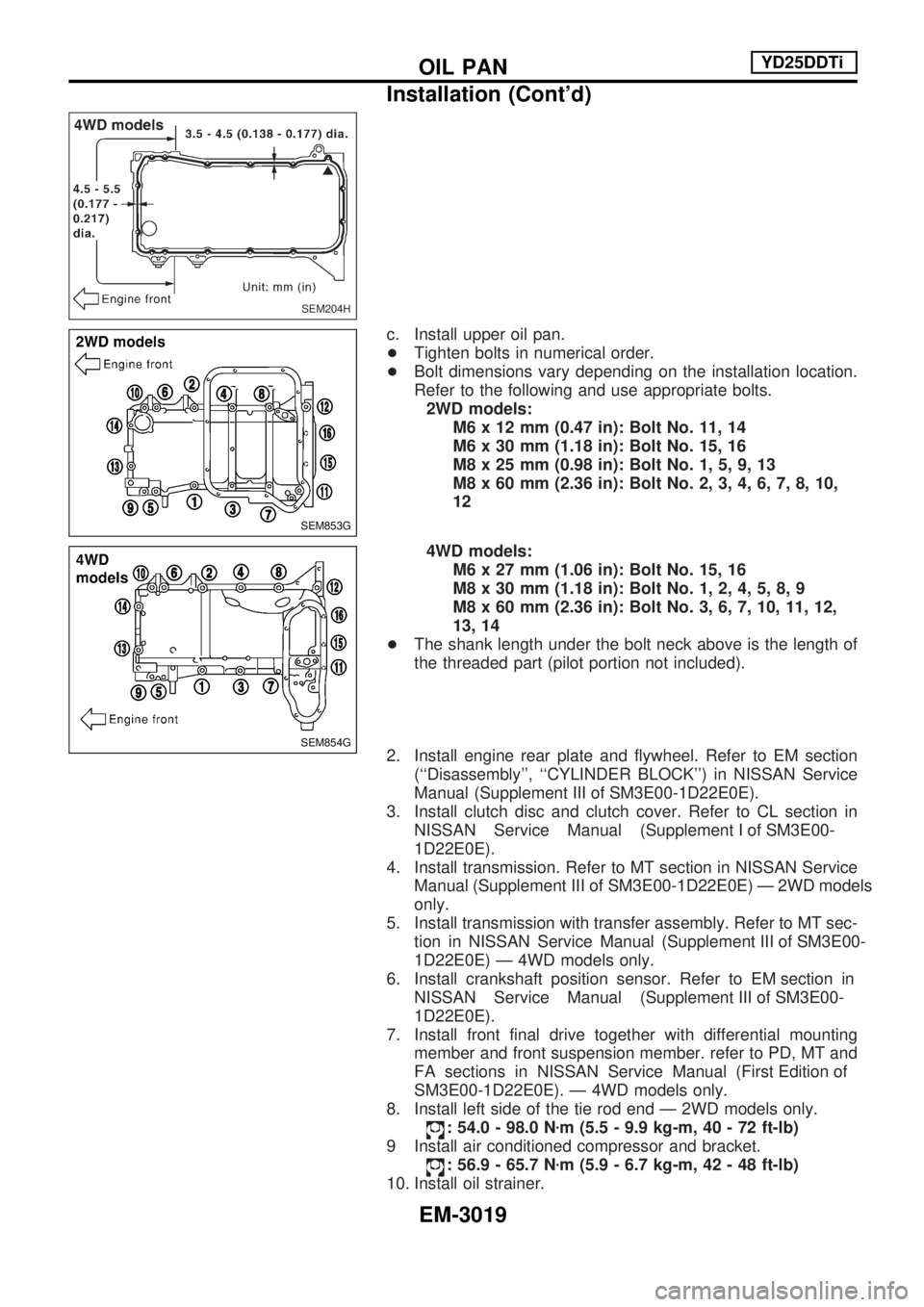
c. Install upper oil pan.
+Tighten bolts in numerical order.
+ Bolt dimensions vary depending on the installation location.
Refer to the following and use appropriate bolts.
2WD models: M6 x 12 mm (0.47 in): Bolt No. 11, 14
M6 x 30 mm (1.18 in): Bolt No. 15, 16
M8 x 25 mm (0.98 in): Bolt No. 1, 5, 9, 13
M8 x 60 mm (2.36 in): Bolt No. 2, 3, 4, 6, 7, 8, 10,
12
4WD models: M6 x 27 mm (1.06 in): Bolt No. 15, 16
M8 x 30 mm (1.18 in): Bolt No. 1, 2, 4, 5, 8, 9
M8 x 60 mm (2.36 in): Bolt No. 3, 6, 7, 10, 11, 12,
13, 14
+ The shank length under the bolt neck above is the length of
the threaded part (pilot portion not included).
2. Install engine rear plate and flywheel. Refer to EM section (``Disassembly'', ``CYLINDER BLOCK'') in NISSAN Service
Manual(Supplement III of SM3E00-1D22E0E).
3. Install clutch disc and clutch cover. Refer to CL section in NISSANServiceManual(Supplement I of SM3E00-
1D22E0E).
4. Install transmission. Refer to MT section in NISSAN Service Manual(Supplement III of SM3E00-1D22E0E)Ð2WDmodels
only.
5. Install transmission with transfer assembly. Refer to MT sec- tioninNISSANServiceManual(Supplement III of SM3E00-
1D22E0E) Ð 4WD models only.
6.Installcrankshaftpositionsensor.RefertoEM sectionin NISSANServiceManual(Supplement III of SM3E00-
1D22E0E).
7. Install front final drive together with differential mounting member and front suspension member. refer to PD, MT and
FAsectionsinNISSANServiceManual(First Edition of
SM3E00-1D22E0E). Ð 4WD models only.
8. Install left side of the tie rod end Ð 2WD models only.
: 54.0 - 98.0 N zm (5.5 - 9.9 kg-m, 40 - 72 ft-lb)
9 Install air conditioned compressor and bracket.
: 56.9 - 65.7 N zm (5.9 - 6.7 kg-m, 42 - 48 ft-lb)
10. Install oil strainer.
SEM204H
SEM853G
SEM854G
OILPAN YD25DDTi
Installation (Cont'd)
EM-3019
Page 975 of 1306
HEATER &
AIR CONDITIONER
SECTION
HA
MODIFICATION NOTICE:
+Wiring Diagrams have been changed.
+Thermo switch has been abolished.
+A/C cycle for YD engine has been added.
CONTENTS
MANUAL AND AUTO
PRECAUTIONS AND PREPARATION............... 3002
Precautions for Refrigerant Connection .......... 3002
MANUAL
TROUBLE DIAGNOSES..................................... 3004
Wiring Diagram - HEATER -............................ 3004
Circuit Diagram - A/C, M - ............................... 3005
Wiring Diagram - A/C, M -/LHD Models with
KA, YD Engine ................................................. 3006
Wiring Diagram - A/C, M -/RHD Models with
KA, YD Engine ................................................. 3009
Magnet Clutch .................................................. 3012
AUTO
TROUBLE DIAGNOSES..................................... 3020
Circuit Diagram - A/C, A -................................ 3020
Wiring Diagram - A/C, A -................................ 3021
Magnet Clutch .................................................. 3026
SERVICE PROCEDURES................................... 3030
Refrigerant Lines.............................................. 3030
MANUAL AND AUTO
SERVICE PROCEDURES................................... 3031
Checking Refrigerant Leaks ............................ 3031
SERVICE PROCEDURES................................... 3032
Compressor Mounting...................................... 3032
MANUAL AND AUTO
SERVICE DATA AND SPECIFICATIONS
(SDS).................................................................... 3033
General Specifications ..................................... 3033
Inspection and Adjustment .............................. 3033
HA