2001 NISSAN PICK-UP ignition
[x] Cancel search: ignitionPage 26 of 1306

ENGINE CONTROL SYSTEM
SECTION
EC
CONTENTS
PRECAUTIONS AND PREPARATION............... 3008
Special Service Tool (YD25DDTi) ................... 3008
Supplemental Restraint System (SRS)²AIR
BAG²................................................................ 3008
KA24DE (EURO OBD)
Trouble Diagnosis - Index................................. 3009
Alphabetical & P No. Index for DTC................ 3009
Precautions......................................................... 3012
Supplemental Restraint System (SRS)²AIR
BAG²and²SEAT BELT PRE-TENSIONER².. 3012
Precautions for On Board Diagnostic (OBD)
System of Engine............................................. 3012
Engine Fuel & Emission Control System ........ 3013
Precautions ...................................................... 3014
Wiring Diagrams and Trouble Diagnosis ......... 3015
Preparation.......................................................... 3016
Special Service Tools ...................................... 3016
Commercial Service Tools ............................... 3016
Engine and Emission Control Overall System3018
Engine Control Component Parts Location ..... 3018
Circuit Diagram ................................................ 3020
System Diagram .............................................. 3021
Vacuum Hose Drawing .................................... 3022
System Chart ................................................... 3023
Engine and Emission Basic Control System
Description.......................................................... 3024
Multiport Fuel Injection (MFI) System.............. 3024
Distributor Ignition (DI) System........................ 3026
Air Conditioning Cut Control ............................ 3028
Fuel Cut Control (at no load & high engine
speed) .............................................................. 3028Evaporative Emission System ......................... 3029
Positive Crankcase Ventilation ........................ 3032
Basic Service Procedure................................... 3033
Fuel Pressure Release .................................... 3033
Fuel Pressure Check ....................................... 3033
Fuel Pressure Regulator Check ...................... 3034
Injector ............................................................. 3034
Fast Idle Cam (FIC) ......................................... 3035
Idle Speed/Ignition Timing/Idle Mixture Ratio
Adjustment ....................................................... 3035
On Board Diagnostic System Description...... 3049
Introduction ...................................................... 3049
Two Trip Detection Logic ................................. 3049
Emission-related Diagnostic Information ......... 3049
NVIS (Nissan Vehicle Immobilizer System -
NATS) .............................................................. 3061
Malfunction Indicator (MI) ................................ 3061
OBD System Operation Chart ......................... 3064
CONSULT-II ..................................................... 3070
Generic Scan Tool (GST) ................................ 3080
Trouble Diagnosis - Introduction..................... 3082
Introduction ...................................................... 3082
Work Flow ........................................................ 3084
Trouble Diagnosis - Basic Inspection.............. 3086
Basic Inspection ............................................... 3086
Trouble Diagnosis - General Description........ 3100
DTC Inspection Priority Chart .......................... 3100
Fail-safe Chart ................................................. 3101
Symptom Matrix Chart ..................................... 3102
CONSULT-II Reference Value in Data Monitor
Mode ................................................................ 3106
Major Sensor Reference Graph in Data
Monitor Mode ................................................... 3107
BR
Page 29 of 1306
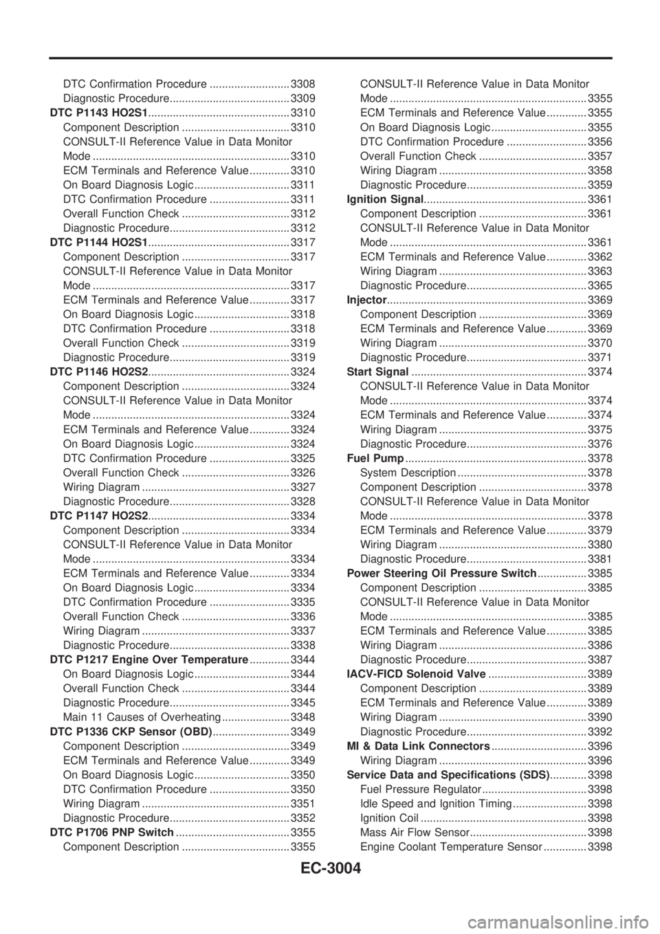
DTC Confirmation Procedure .......................... 3308
Diagnostic Procedure....................................... 3309
DTC P1143 HO2S1.............................................. 3310
Component Description ................................... 3310
CONSULT-II Reference Value in Data Monitor
Mode ................................................................ 3310
ECM Terminals and Reference Value ............. 3310
On Board Diagnosis Logic ............................... 3311
DTC Confirmation Procedure .......................... 3311
Overall Function Check ................................... 3312
Diagnostic Procedure....................................... 3312
DTC P1144 HO2S1.............................................. 3317
Component Description ................................... 3317
CONSULT-II Reference Value in Data Monitor
Mode ................................................................ 3317
ECM Terminals and Reference Value ............. 3317
On Board Diagnosis Logic ............................... 3318
DTC Confirmation Procedure .......................... 3318
Overall Function Check ................................... 3319
Diagnostic Procedure....................................... 3319
DTC P1146 HO2S2.............................................. 3324
Component Description ................................... 3324
CONSULT-II Reference Value in Data Monitor
Mode ................................................................ 3324
ECM Terminals and Reference Value ............. 3324
On Board Diagnosis Logic ............................... 3324
DTC Confirmation Procedure .......................... 3325
Overall Function Check ................................... 3326
Wiring Diagram ................................................ 3327
Diagnostic Procedure....................................... 3328
DTC P1147 HO2S2.............................................. 3334
Component Description ................................... 3334
CONSULT-II Reference Value in Data Monitor
Mode ................................................................ 3334
ECM Terminals and Reference Value ............. 3334
On Board Diagnosis Logic ............................... 3334
DTC Confirmation Procedure .......................... 3335
Overall Function Check ................................... 3336
Wiring Diagram ................................................ 3337
Diagnostic Procedure....................................... 3338
DTC P1217 Engine Over Temperature............. 3344
On Board Diagnosis Logic ............................... 3344
Overall Function Check ................................... 3344
Diagnostic Procedure....................................... 3345
Main 11 Causes of Overheating ...................... 3348
DTC P1336 CKP Sensor (OBD)......................... 3349
Component Description ................................... 3349
ECM Terminals and Reference Value ............. 3349
On Board Diagnosis Logic ............................... 3350
DTC Confirmation Procedure .......................... 3350
Wiring Diagram ................................................ 3351
Diagnostic Procedure....................................... 3352
DTC P1706 PNP Switch..................................... 3355
Component Description ................................... 3355CONSULT-II Reference Value in Data Monitor
Mode ................................................................ 3355
ECM Terminals and Reference Value ............. 3355
On Board Diagnosis Logic ............................... 3355
DTC Confirmation Procedure .......................... 3356
Overall Function Check ................................... 3357
Wiring Diagram ................................................ 3358
Diagnostic Procedure....................................... 3359
Ignition Signal..................................................... 3361
Component Description ................................... 3361
CONSULT-II Reference Value in Data Monitor
Mode ................................................................ 3361
ECM Terminals and Reference Value ............. 3362
Wiring Diagram ................................................ 3363
Diagnostic Procedure....................................... 3365
Injector................................................................. 3369
Component Description ................................... 3369
ECM Terminals and Reference Value ............. 3369
Wiring Diagram ................................................ 3370
Diagnostic Procedure....................................... 3371
Start Signal......................................................... 3374
CONSULT-II Reference Value in Data Monitor
Mode ................................................................ 3374
ECM Terminals and Reference Value ............. 3374
Wiring Diagram ................................................ 3375
Diagnostic Procedure....................................... 3376
Fuel Pump........................................................... 3378
System Description .......................................... 3378
Component Description ................................... 3378
CONSULT-II Reference Value in Data Monitor
Mode ................................................................ 3378
ECM Terminals and Reference Value ............. 3379
Wiring Diagram ................................................ 3380
Diagnostic Procedure....................................... 3381
Power Steering Oil Pressure Switch................ 3385
Component Description ................................... 3385
CONSULT-II Reference Value in Data Monitor
Mode ................................................................ 3385
ECM Terminals and Reference Value ............. 3385
Wiring Diagram ................................................ 3386
Diagnostic Procedure....................................... 3387
IACV-FICD Solenoid Valve................................ 3389
Component Description ................................... 3389
ECM Terminals and Reference Value ............. 3389
Wiring Diagram ................................................ 3390
Diagnostic Procedure....................................... 3392
MI & Data Link Connectors............................... 3396
Wiring Diagram ................................................ 3396
Service Data and Specifications (SDS)............ 3398
Fuel Pressure Regulator .................................. 3398
Idle Speed and Ignition Timing ........................ 3398
Ignition Coil ...................................................... 3398
Mass Air Flow Sensor...................................... 3398
Engine Coolant Temperature Sensor .............. 3398
EC-3004
Page 37 of 1306
Supplemental Restraint System (SRS) ªAIR
BAGº and ªSEAT BELT PRE-TENSIONERº
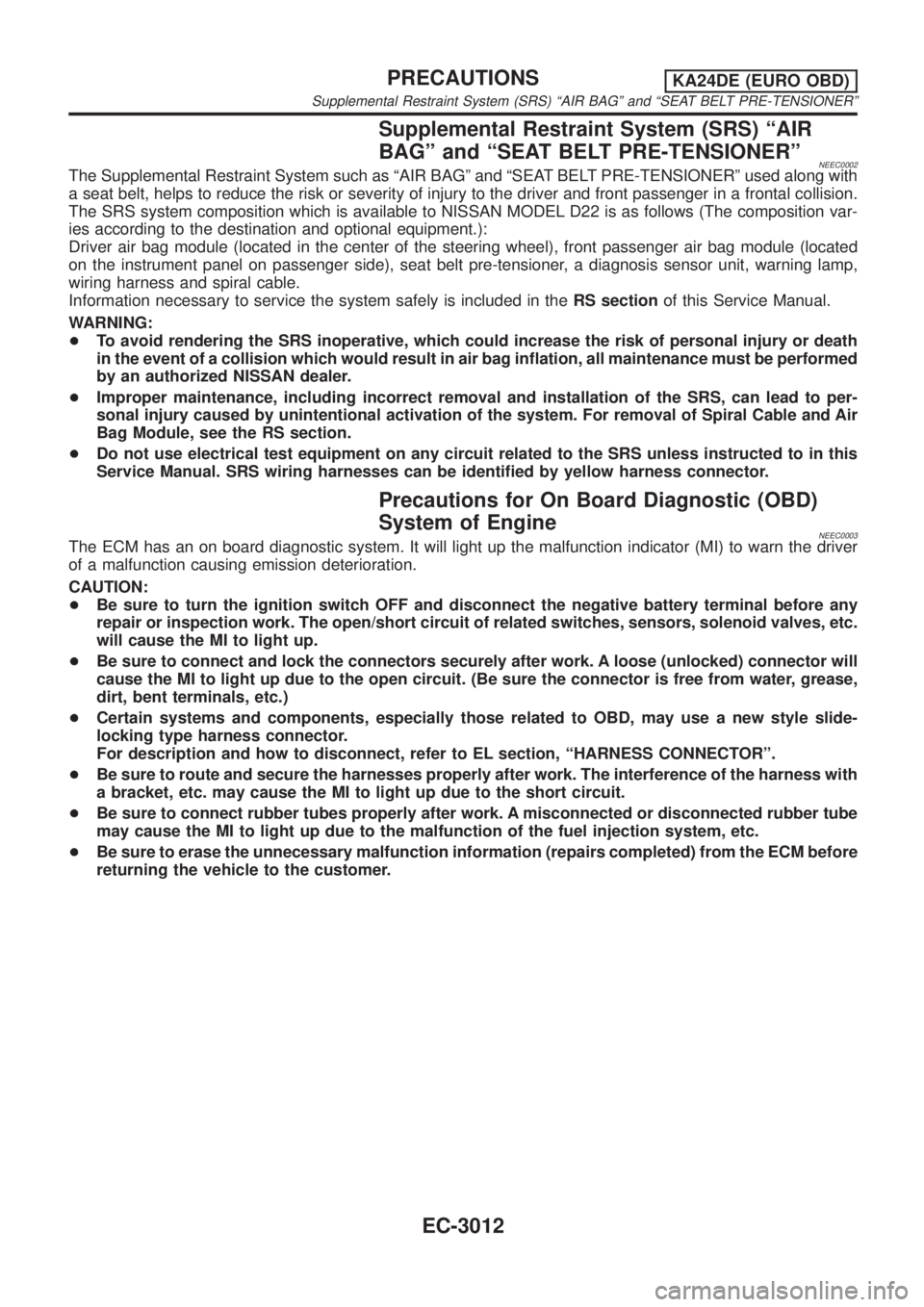
NEEC0002The Supplemental Restraint System such as ªAIR BAGº and ªSEAT BELT PRE-TENSIONERº used along with
a seat belt, helps to reduce the risk or severity of injury to the driver and front passenger in a frontal collision.
The SRS system composition which is available to NISSAN MODEL D22 is as follows (The composition var-
ies according to the destination and optional equipment.):
Driver air bag module (located in the center of the steering wheel), front passenger air bag module (located
on the instrument panel on passenger side), seat belt pre-tensioner, a diagnosis sensor unit, warning lamp,
wiring harness and spiral cable.
Information necessary to service the system safely is included in theRS sectionof this Service Manual.
WARNING:
+To avoid rendering the SRS inoperative, which could increase the risk of personal injury or death
in the event of a collision which would result in air bag inflation, all maintenance must be performed
by an authorized NISSAN dealer.
+Improper maintenance, including incorrect removal and installation of the SRS, can lead to per-
sonal injury caused by unintentional activation of the system. For removal of Spiral Cable and Air
Bag Module, see the RS section.
+Do not use electrical test equipment on any circuit related to the SRS unless instructed to in this
Service Manual. SRS wiring harnesses can be identified by yellow harness connector.
Precautions for On Board Diagnostic (OBD)
System of Engine
NEEC0003The ECM has an on board diagnostic system. It will light up the malfunction indicator (MI) to warn the driver
of a malfunction causing emission deterioration.
CAUTION:
+Be sure to turn the ignition switch OFF and disconnect the negative battery terminal before any
repair or inspection work. The open/short circuit of related switches, sensors, solenoid valves, etc.
will cause the MI to light up.
+Be sure to connect and lock the connectors securely after work. A loose (unlocked) connector will
cause the MI to light up due to the open circuit. (Be sure the connector is free from water, grease,
dirt, bent terminals, etc.)
+Certain systems and components, especially those related to OBD, may use a new style slide-
locking type harness connector.
For description and how to disconnect, refer to EL section, ªHARNESS CONNECTORº.
+Be sure to route and secure the harnesses properly after work. The interference of the harness with
a bracket, etc. may cause the MI to light up due to the short circuit.
+Be sure to connect rubber tubes properly after work. A misconnected or disconnected rubber tube
may cause the MI to light up due to the malfunction of the fuel injection system, etc.
+Be sure to erase the unnecessary malfunction information (repairs completed) from the ECM before
returning the vehicle to the customer.
PRECAUTIONSKA24DE (EURO OBD)
Supplemental Restraint System (SRS) ªAIR BAGº and ªSEAT BELT PRE-TENSIONERº
EC-3012
Page 39 of 1306
SEF289H
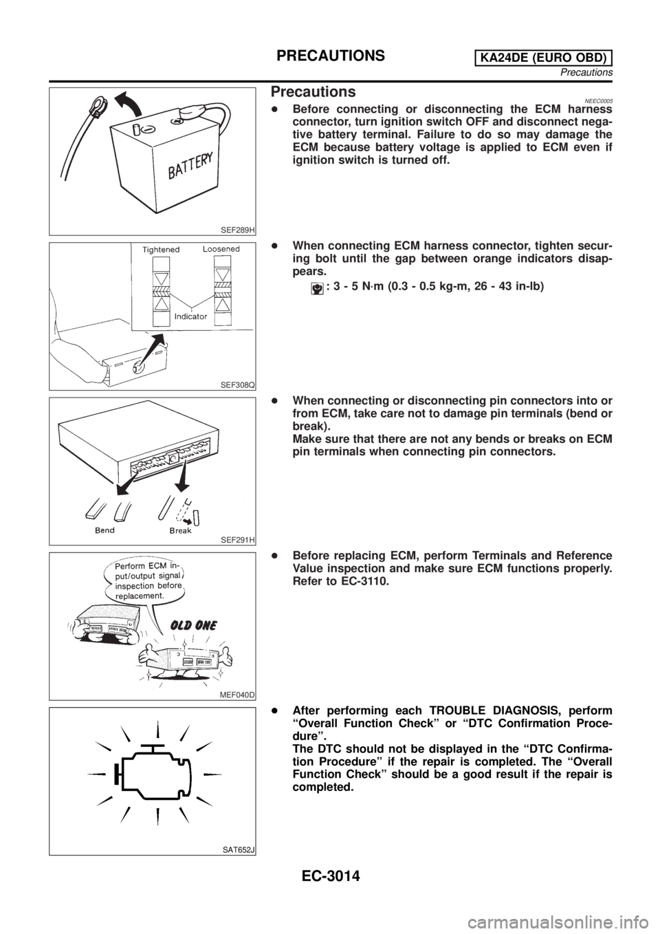
PrecautionsNEEC0005+Before connecting or disconnecting the ECM harness
connector, turn ignition switch OFF and disconnect nega-
tive battery terminal. Failure to do so may damage the
ECM because battery voltage is applied to ECM even if
ignition switch is turned off.
SEF308Q
+When connecting ECM harness connector, tighten secur-
ing bolt until the gap between orange indicators disap-
pears.
:3-5N´m(0.3 - 0.5 kg-m, 26 - 43 in-lb)
SEF291H
+When connecting or disconnecting pin connectors into or
from ECM, take care not to damage pin terminals (bend or
break).
Make sure that there are not any bends or breaks on ECM
pin terminals when connecting pin connectors.
MEF040D
+Before replacing ECM, perform Terminals and Reference
Value inspection and make sure ECM functions properly.
Refer to EC-3110.
SAT652J
+After performing each TROUBLE DIAGNOSIS, perform
ªOverall Function Checkº or ªDTC Confirmation Proce-
dureº.
The DTC should not be displayed in the ªDTC Confirma-
tion Procedureº if the repair is completed. The ªOverall
Function Checkº should be a good result if the repair is
completed.
PRECAUTIONSKA24DE (EURO OBD)
Precautions
EC-3014
Page 48 of 1306
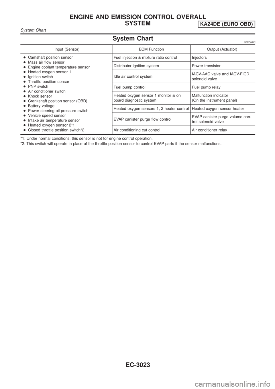
System ChartNEEC0013
Input (Sensor) ECM Function Output (Actuator)
+Camshaft position sensor
+Mass air flow sensor
+Engine coolant temperature sensor
+Heated oxygen sensor 1
+Ignition switch
+Throttle position sensor
+PNP switch
+Air conditioner switch
+Knock sensor
+Crankshaft position sensor (OBD)
+Battery voltage
+Power steering oil pressure switch
+Vehicle speed sensor
+Intake air temperature sensor
+Heated oxygen sensor 2*1
+Closed throttle position switch*2Fuel injection & mixture ratio control Injectors
Distributor ignition system Power transistor
Idle air control systemIACV-AAC valve and IACV-FICD
solenoid valve
Fuel pump control Fuel pump relay
Heated oxygen sensor 1 monitor & on
board diagnostic systemMalfunction indicator
(On the instrument panel)
Heated oxygen sensors 1, 2 heater control Heated oxygen sensor heater
EVAP canister purge flow controlEVAP canister purge volume con-
trol solenoid valve
Air conditioning cut control Air conditioner relay
*1: Under normal conditions, this sensor is not for engine control operation.
*2: This switch will operate in place of the throttle position sensor to control EVAP parts if the sensor malfunctions.
ENGINE AND EMISSION CONTROL OVERALL
SYSTEM
KA24DE (EURO OBD)
System Chart
EC-3023
Page 49 of 1306

Multiport Fuel Injection (MFI) System
DESCRIPTIONNEEC0014Input/Output Signal ChartNEEC0014S01
Sensor Input Signal to ECMECM func-
tionActuator
Camshaft position sensor Engine speed and piston position
Fuel injec-
tion & mix-
ture ratio
controlInjector Mass air flow sensor Amount of intake air
Engine coolant temperature sensor Engine coolant temperature
Heated oxygen sensor 1 Density of oxygen in exhaust gas
Throttle position sensorThrottle position
Throttle valve idle position
PNP switch Gear position
Vehicle speed sensor Vehicle speed
Ignition switch Start signal
Air conditioner switch Air conditioner operation
Knock sensor Engine knocking condition
Battery Battery voltage
Power steering oil pressure switch Power steering operation
Heated oxygen sensor 2* Density of oxygen in exhaust gas
* Under normal conditions, this sensor is not for engine control operation.
Basic Multiport Fuel Injection SystemNEEC0014S02The amount of fuel injected from the fuel injector is determined by the ECM. The ECM controls the length of
time the valve remains open (injection pulse duration). The amount of fuel injected is a program value in the
ECM memory. The program value is preset by engine operating conditions. These conditions are determined
by input signals (for engine speed and intake air) from both the camshaft position sensor and the mass air
flow sensor.
Various Fuel Injection Increase/Decrease CompensationNEEC0014S03In addition, the amount of fuel injected is compensated to improve engine performance under various oper-
ating conditions as listed below.
+During warm-up
+When starting the engine
+During acceleration
+Hot-engine operation
+High-load, high-speed operation
+During deceleration
+During high engine speed operation
ENGINE AND EMISSION BASIC CONTROL SYSTEM
DESCRIPTION
KA24DE (EURO OBD)
Multiport Fuel Injection (MFI) System
EC-3024
Page 51 of 1306

Fuel Injection TimingNEEC0014S07
SEF337W
Two types of systems are used.
Sequential Multiport Fuel Injection System
NEEC0014S0701Fuel is injected into each cylinder during each engine cycle according to the firing order. This system is used
when the engine is running.
Simultaneous Multiport Fuel Injection System
NEEC0014S0702Fuel is injected simultaneously into all four cylinders twice each engine cycle. In other words, pulse signals of
the same width are simultaneously transmitted from the ECM.
The four injectors will then receive the signals two times for each engine cycle.
This system is used when the engine is being started and/or if the fail-safe system (CPU) is operating.
Fuel Shut-offNEEC0014S08Fuel to each cylinder is cut off during deceleration or operation of the engine at excessively high speeds.
Distributor Ignition (DI) System
DESCRIPTIONNEEC0015Input/Output Signal ChartNEEC0015S01
Sensor Input Signal to ECMECM func-
tionActuator
Camshaft position sensor Engine speed and piston position
Ignition tim-
ing controlPower transistor Mass air flow sensor Amount of intake air
Engine coolant temperature sensor Engine coolant temperature
Throttle position sensorThrottle position
Throttle valve idle position
Vehicle speed sensor Vehicle speed
Ignition switch Start signal
Knock sensor Engine knocking
PNP switch Gear position
Battery Battery voltage
ENGINE AND EMISSION BASIC CONTROL SYSTEM
DESCRIPTION
KA24DE (EURO OBD)
Multiport Fuel Injection (MFI) System
EC-3026
Page 52 of 1306
System DescriptionNEEC0015S02
SEF742M
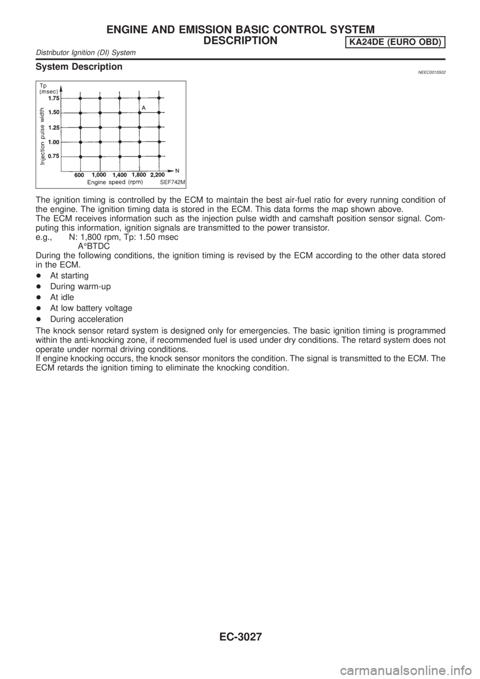
The ignition timing is controlled by the ECM to maintain the best air-fuel ratio for every running condition of
the engine. The ignition timing data is stored in the ECM. This data forms the map shown above.
The ECM receives information such as the injection pulse width and camshaft position sensor signal. Com-
puting this information, ignition signals are transmitted to the power transistor.
e.g., N: 1,800 rpm, Tp: 1.50 msec
AÉBTDC
During the following conditions, the ignition timing is revised by the ECM according to the other data stored
in the ECM.
+At starting
+During warm-up
+At idle
+At low battery voltage
+During acceleration
The knock sensor retard system is designed only for emergencies. The basic ignition timing is programmed
within the anti-knocking zone, if recommended fuel is used under dry conditions. The retard system does not
operate under normal driving conditions.
If engine knocking occurs, the knock sensor monitors the condition. The signal is transmitted to the ECM. The
ECM retards the ignition timing to eliminate the knocking condition.
ENGINE AND EMISSION BASIC CONTROL SYSTEM
DESCRIPTION
KA24DE (EURO OBD)
Distributor Ignition (DI) System
EC-3027