2001 NISSAN PICK-UP coolant level
[x] Cancel search: coolant levelPage 60 of 1306

SEF500V
Fast Idle Cam (FIC)
COMPONENT DESCRIPTIONNEEC0502The FIC is installed on the throttle body to maintain adequate
engine speed while the engine is cold. It is operated by a volumet-
ric change in wax located inside the thermo-element. The thermo-
element is operated by engine coolant temperature.
For inspection refer to ªTROUBLE DIAGNOSIS-BASIC
INSPECTIONº, ªBasic Inspectionº, EC-3086.
Idle Speed/Ignition Timing/Idle Mixture Ratio
Adjustment
NEEC0028PREPARATIONNEEC0028S05+Make sure that the following parts are in good order.
a)Battery
b)Ignition system
c)Engine oil and coolant levels
d)Fuses
e)ECM harness connector
f)Vacuum hoses
g)Air intake system
(Oil filler cap, oil level gauge, etc.)
h)Fuel pressure
i)Engine compression
j)Throttle valve
k)EVAP system
+On models equipped with air conditioner, checks should be carried out while the air conditioner is
ªOFFº.
+When measuring ªCOº percentage, insert probe more than 40 cm (15.7 in) into tail pipe.
+Turn off headlamps, heater blower.
+Keep front wheels pointed straight ahead.
BASIC SERVICE PROCEDUREKA24DE (EURO OBD)
Fast Idle Cam (FIC)
EC-3035
Page 82 of 1306
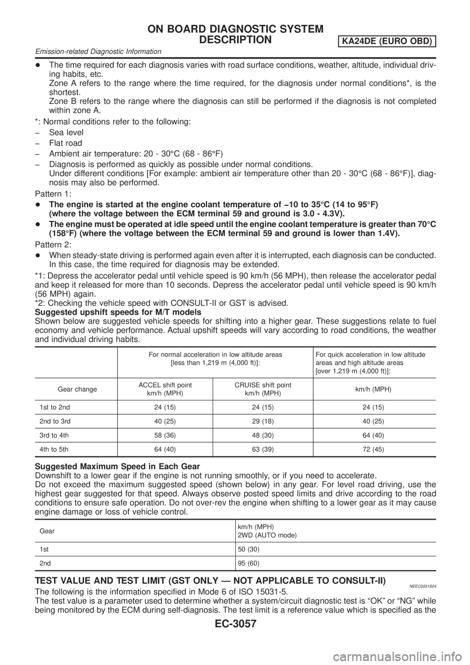
+The time required for each diagnosis varies with road surface conditions, weather, altitude, individual driv-
ing habits, etc.
Zone A refers to the range where the time required, for the diagnosis under normal conditions*, is the
shortest.
Zone B refers to the range where the diagnosis can still be performed if the diagnosis is not completed
within zone A.
*: Normal conditions refer to the following:
þ Sea level
þ Flat road
þ Ambient air temperature: 20 - 30ÉC (68 - 86ÉF)
þ Diagnosis is performed as quickly as possible under normal conditions.
Under different conditions [For example: ambient air temperature other than 20 - 30ÉC (68 - 86ÉF)], diag-
nosis may also be performed.
Pattern 1:
+The engine is started at the engine coolant temperature of þ10 to 35ÉC (14 to 95ÉF)
(where the voltage between the ECM terminal 59 and ground is 3.0 - 4.3V).
+The engine must be operated at idle speed until the engine coolant temperature is greater than 70ÉC
(158ÉF) (where the voltage between the ECM terminal 59 and ground is lower than 1.4V).
Pattern 2:
+When steady-state driving is performed again even after it is interrupted, each diagnosis can be conducted.
In this case, the time required for diagnosis may be extended.
*1: Depress the accelerator pedal until vehicle speed is 90 km/h (56 MPH), then release the accelerator pedal
and keep it released for more than 10 seconds. Depress the accelerator pedal until vehicle speed is 90 km/h
(56 MPH) again.
*2: Checking the vehicle speed with CONSULT-II or GST is advised.
Suggested upshift speeds for M/T models
Shown below are suggested vehicle speeds for shifting into a higher gear. These suggestions relate to fuel
economy and vehicle performance. Actual upshift speeds will vary according to road conditions, the weather
and individual driving habits.
For normal acceleration in low altitude areas
[less than 1,219 m (4,000 ft)]:For quick acceleration in low altitude
areas and high altitude areas
[over 1,219 m (4,000 ft)]:
Gear changeACCEL shift point
km/h (MPH)CRUISE shift point
km/h (MPH)km/h (MPH)
1st to 2nd 24 (15) 24 (15) 24 (15)
2nd to 3rd 40 (25) 29 (18) 40 (25)
3rd to 4th 58 (36) 48 (30) 64 (40)
4th to 5th 64 (40) 63 (39) 72 (45)
Suggested Maximum Speed in Each Gear
Downshift to a lower gear if the engine is not running smoothly, or if you need to accelerate.
Do not exceed the maximum suggested speed (shown below) in any gear. For level road driving, use the
highest gear suggested for that speed. Always observe posted speed limits and drive according to the road
conditions to ensure safe operation. Do not over-rev the engine when shifting to a lower gear as it may cause
engine damage or loss of vehicle control.
Gearkm/h (MPH)
2WD (AUTO mode)
1st 50 (30)
2nd 95 (60)
TEST VALUE AND TEST LIMIT (GST ONLY Ð NOT APPLICABLE TO CONSULT-II)NEEC0031S04The following is the information specified in Mode 6 of ISO 15031-5.
The test value is a parameter used to determine whether a system/circuit diagnostic test is ªOKº or ªNGº while
being monitored by the ECM during self-diagnosis. The test limit is a reference value which is specified as the
ON BOARD DIAGNOSTIC SYSTEM
DESCRIPTION
KA24DE (EURO OBD)
Emission-related Diagnostic Information
EC-3057
Page 130 of 1306
SYMPTOM
Reference
page
HARD/NO START/RESTART (EXCP. HA)
ENGINE STALL
HESITATION/SURGING/FLAT SPOT
SPARK KNOCK/DETONATION
LACK OF POWER/POOR ACCELERATION
HIGH IDLE/LOW IDLE
ROUGH IDLE/HUNTING
IDLING VIBRATION
SLOW/NO RETURN TO IDLE
OVERHEATS/WATER TEMPERATURE HIGH
EXCESSIVE FUEL CONSUMPTION
EXCESSIVE OIL CONSUMPTION
BATTERY DEAD (UNDER CHARGE)
Warranty symptom code AA AB AC AD AE AF AG AH AJ AK AL AM HA
Engine Cylinder head
55555 55 5
EM section Cylinder head gasket 4 3
Cylinder block
66666 66 64 Piston
Piston ring
Connecting rod
Bearing
Crankshaft
Valve
mecha-
nismTiming chain
5 5 5 5 5 5 5 5 EM section Camshaft
Intake valve
3
Exhaust valve
Exhaust Exhaust manifold/Tube/
Muffler/Gasket
5 5 5 5 5 5 5 5 FE section
Three way catalyst
Lubrica-
tionOil pan/Oil strainer/Oil pump/
Oil filter/Oil gallery
55555 55 5MA section,
LC section
Oil level (Low)/Filthy oil
Cooling Radiator/Hose/Radiator filler
cap
55555 55 45LC section Thermostat 5
Water pump
Water gallery
Coolant level (low)/
Contaminated coolantMA section
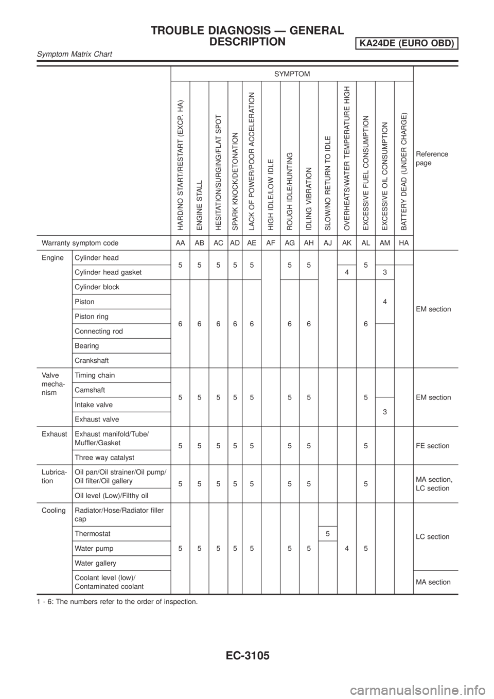
1 - 6: The numbers refer to the order of inspection.
TROUBLE DIAGNOSIS Ð GENERAL
DESCRIPTION
KA24DE (EURO OBD)
Symptom Matrix Chart
EC-3105
Page 253 of 1306
SEF841Y
DTC Confirmation ProcedureNEEC0166
SEF842Y
SEF843Y
CAUTION:
Always drive vehicle at a safe speed.
NOTE:
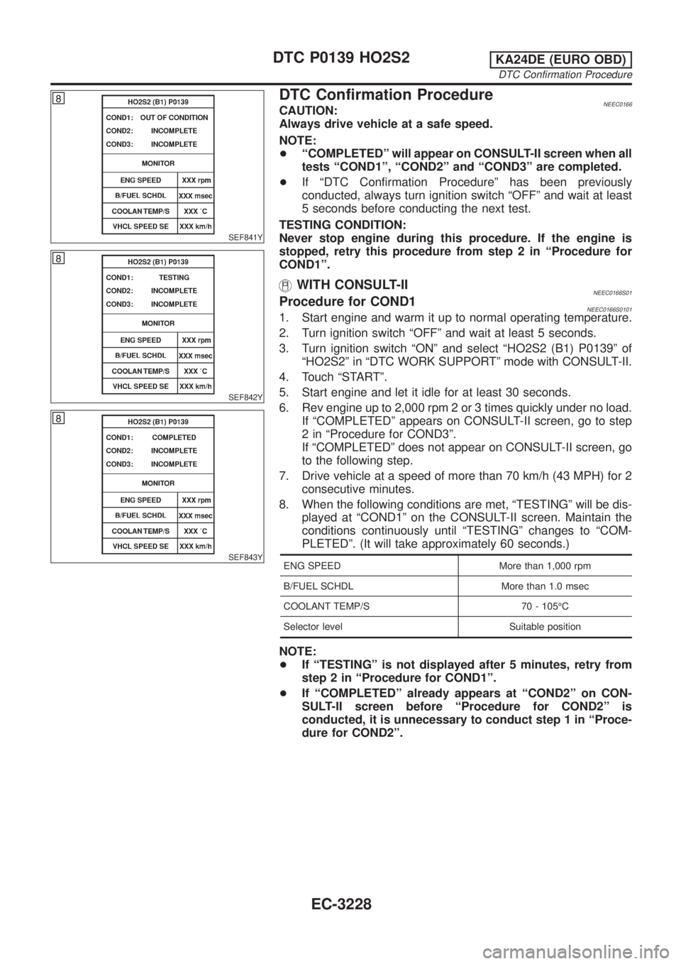
+ªCOMPLETEDº will appear on CONSULT-II screen when all
tests ªCOND1º, ªCOND2º and ªCOND3º are completed.
+If ªDTC Confirmation Procedureº has been previously
conducted, always turn ignition switch ªOFFº and wait at least
5 seconds before conducting the next test.
TESTING CONDITION:
Never stop engine during this procedure. If the engine is
stopped, retry this procedure from step 2 in ªProcedure for
COND1º.
WITH CONSULT-IINEEC0166S01Procedure for COND1NEEC0166S01011. Start engine and warm it up to normal operating temperature.
2. Turn ignition switch ªOFFº and wait at least 5 seconds.
3. Turn ignition switch ªONº and select ªHO2S2 (B1) P0139º of
ªHO2S2º in ªDTC WORK SUPPORTº mode with CONSULT-II.
4. Touch ªSTARTº.
5. Start engine and let it idle for at least 30 seconds.
6. Rev engine up to 2,000 rpm 2 or 3 times quickly under no load.
If ªCOMPLETEDº appears on CONSULT-II screen, go to step
2 in ªProcedure for COND3º.
If ªCOMPLETEDº does not appear on CONSULT-II screen, go
to the following step.
7. Drive vehicle at a speed of more than 70 km/h (43 MPH) for 2
consecutive minutes.
8. When the following conditions are met, ªTESTINGº will be dis-
played at ªCOND1º on the CONSULT-II screen. Maintain the
conditions continuously until ªTESTINGº changes to ªCOM-
PLETEDº. (It will take approximately 60 seconds.)
ENG SPEED More than 1,000 rpm
B/FUEL SCHDL More than 1.0 msec
COOLANT TEMP/S 70 - 105ÉC
Selector level Suitable position
NOTE:
+If ªTESTINGº is not displayed after 5 minutes, retry from
step 2 in ªProcedure for COND1º.
+If ªCOMPLETEDº already appears at ªCOND2º on CON-
SULT-II screen before ªProcedure for COND2º is
conducted, it is unnecessary to conduct step 1 in ªProce-
dure for COND2º.
DTC P0139 HO2S2KA24DE (EURO OBD)
DTC Confirmation Procedure
EC-3228
Page 320 of 1306
DescriptionNEEC1594SYSTEM DESCRIPTIONNEEC1594S01
Sensor Input Signal to ECMECM func-
tionActuator
Camshaft position sensor Engine speed
Idle air
controlIACV-AAC valve Mass air flow sensor Amount of intake air
Engine coolant temperature sensor Engine coolant temperature
Ignition switch Start signal
Throttle position sensor Throttle position
PNP switch Neutral position
Air conditioner switch Air conditioner operation
Power steering oil pressure switch Power steering load signal
Battery Battery voltage
Vehicle speed sensor Vehicle speed
Intake air temperature sensor Intake air temperature
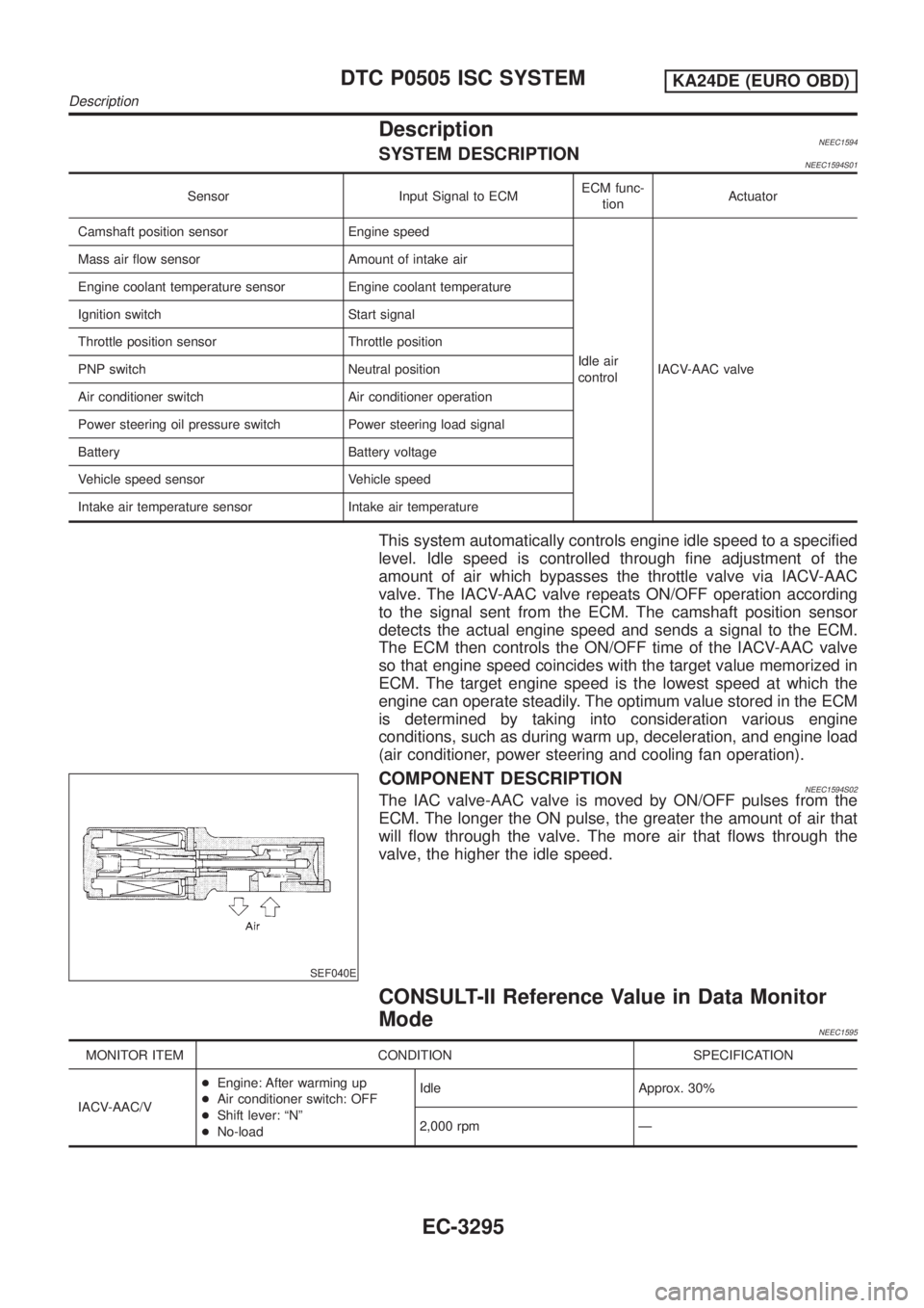
This system automatically controls engine idle speed to a specified
level. Idle speed is controlled through fine adjustment of the
amount of air which bypasses the throttle valve via IACV-AAC
valve. The IACV-AAC valve repeats ON/OFF operation according
to the signal sent from the ECM. The camshaft position sensor
detects the actual engine speed and sends a signal to the ECM.
The ECM then controls the ON/OFF time of the IACV-AAC valve
so that engine speed coincides with the target value memorized in
ECM. The target engine speed is the lowest speed at which the
engine can operate steadily. The optimum value stored in the ECM
is determined by taking into consideration various engine
conditions, such as during warm up, deceleration, and engine load
(air conditioner, power steering and cooling fan operation).
SEF040E
COMPONENT DESCRIPTIONNEEC1594S02The IAC valve-AAC valve is moved by ON/OFF pulses from the
ECM. The longer the ON pulse, the greater the amount of air that
will flow through the valve. The more air that flows through the
valve, the higher the idle speed.
CONSULT-II Reference Value in Data Monitor
Mode
NEEC1595
MONITOR ITEM CONDITION SPECIFICATION
IACV-AAC/V+Engine: After warming up
+Air conditioner switch: OFF
+Shift lever: ªNº
+No-loadIdle Approx. 30%
2,000 rpm Ð
DTC P0505 ISC SYSTEMKA24DE (EURO OBD)
Description
EC-3295
Page 350 of 1306

SEC314D
DTC Confirmation ProcedureNEEC0148
SEC315D
SEC316D
CAUTION:
Always drive vehicle at a safe speed.
NOTE:
+ªCOMPLETEDº will appear on CONSULT-II screen when all
tests ªCOND1º, ªCOND2º and ªCOND3º are completed.
+If ªDTC Confirmation Procedureº has been previously
conducted, always turn ignition switch ªOFFº and wait at least
5 seconds before conducting the next test.
TESTING CONDITION:
Never stop engine during this procedure. If the engine is
stopped, retry this procedure from step 2 in ªProcedure for
COND1º.
WITH CONSULT-IINEEC0148S01Procedure for COND1NEEC0148S01011. Start engine and warm it up to normal operating temperature.
2. Turn ignition switch ªOFFº and wait at least 5 seconds.
3. Turn ignition switch ªONº and select ªHO2S2 (B1) P1146º of
ªHO2S2º in ªDTC WORK SUPPORTº mode with CONSULT-II.
4. Touch ªSTARTº.
5. Start engine and let it idle for at least 30 seconds.
6. Rev engine up to 2,000 rpm 2 or 3 times quickly under no load.
If ªCOMPLETEDº appears on CONSULT-II screen, go to step
2 in ªProcedure for COND3º.
If ªCOMPLETEDº does not appear on CONSULT-II screen, go
to the following step.
7. Drive vehicle at a speed of more than 70 km/h (43 MPH) for 2
consecutive minutes.
8. When the following conditions are met, ªTESTINGº will be dis-
played at ªCOND1º on the CONSULT-II screen. Maintain the
conditions continuously until ªTESTINGº changes to ªCOM-
PLETEDº. (It will take approximately 60 seconds.)
ENG SPEED More than 1,000 rpm
B/FUEL SCHDL More than 1.0 msec
COOLANT TEMP/S 70 - 105ÉC
Selector level Suitable position
NOTE:
+If ªTESTINGº is not displayed after 5 minutes, retry from
step 2 in ªProcedure for COND1º.
+If ªCOMPLETEDº already appears at ªCOND2º on CON-
SULT-II screen before ªProcedure for COND2º is
conducted, it is unnecessary to conduct step 1 in ªProce-
dure for COND2º.
DTC P1146 HO2S2KA24DE (EURO OBD)
DTC Confirmation Procedure
EC-3325
Page 360 of 1306

SEC340D
DTC Confirmation ProcedureNEEC0157
SEC341D
SEC342D
CAUTION:
Always drive vehicle at a safe speed.
NOTE:
+ªCOMPLETEDº will appear on CONSULT-II screen when all
tests ªCOND1º, ªCOND2º and ªCOND3º are completed.
+If ªDTC Confirmation Procedureº has been previously
conducted, always turn ignition switch ªOFFº and wait at least
5 seconds before conducting the next test.
TESTING CONDITION:
Never stop engine during this procedure. If the engine is
stopped, retry this procedure from step 2 in ªProcedure for
COND1º.
WITH CONSULT-IINEEC0157S01Procedure for COND1NEEC0157S01011. Start engine and warm it up to normal operating temperature.
2. Turn ignition switch ªOFFº and wait at least 5 seconds.
3. Turn ignition switch ªONº and select ªHO2S2 (B1) P1147º of
ªHO2S2º in ªDTC WORK SUPPORTº mode with CONSULT-II.
4. Touch ªSTARTº.
5. Start engine and let it idle for at least 30 seconds.
6. Rev engine up to 2,000 rpm 2 or 3 times quickly under no load.
If ªCOMPLETEDº appears on CONSULT-II screen, go to step
2 in ªProcedure for COND3º.
If ªCOMPLETEDº does not appear on CONSULT-II screen, go
to the following step.
7. Drive vehicle at a speed of more than 70 km/h (43 MPH) for 2
consecutive minutes.
8. When the following conditions are met, ªTESTINGº will be dis-
played at ªCOND1º on the CONSULT-II screen. Maintain the
conditions continuously until ªTESTINGº changes to ªCOM-
PLETEDº. (It will take approximately 60 seconds.)
ENG SPEED More than 1,000 rpm
B/FUEL SCHDL More than 1.0 msec
COOLANT TEMP/S 70 - 105ÉC
Selector level Suitable position
NOTE:
+If ªTESTINGº is not displayed after 5 minutes, retry from
step 2 in ªProcedure for COND1º.
+If ªCOMPLETEDº already appears at ªCOND2º on CON-
SULT-II screen before ªProcedure for COND2º is
conducted, it is unnecessary to conduct step 1 in ªProce-
dure for COND2º.
DTC P1147 HO2S2KA24DE (EURO OBD)
DTC Confirmation Procedure
EC-3335
Page 369 of 1306
On Board Diagnosis LogicNEEC1534If the cooling fan or another component in the cooling system malfunctions, engine coolant temperature will
rise.
When the engine coolant temperature reaches an abnormally high temperature condition, a malfunction is
indicated.
DTC No. Malfunction is detected when ...Check Items
(Possible Cause)
P1217
1217+Engine coolant temperature reaches an abnormally high
temperature.+Cooling fan (crankshaft driven)
Radiator hose
+Radiator
+Radiator cap
+Water pump
+Thermostat
+Engine coolant temperature sensor
For more information, refer to ªMAIN 11 CAUSES
OF OVERHEATINGº, EC-3348.
CAUTION:
When a malfunction is indicated, be sure to replace the coolant. Refer to MA section, ªChanging Engine
Coolantº. Also, replace the engine oil.
1) Fill radiator with coolant up to specified level with a filling speed of 2 liters per minute. Be sure
to use coolant with the proper mixture ratio. Refer to MA section, ªAnti-freeze Coolant Mixture
Ratioº.
2) After refilling coolant, run engine to ensure that no water-flow noise is emitted.
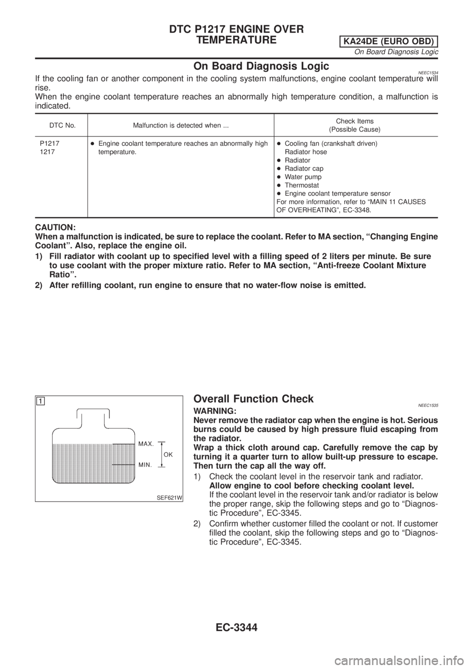
SEF621W
Overall Function CheckNEEC1535WARNING:
Never remove the radiator cap when the engine is hot. Serious
burns could be caused by high pressure fluid escaping from
the radiator.
Wrap a thick cloth around cap. Carefully remove the cap by
turning it a quarter turn to allow built-up pressure to escape.
Then turn the cap all the way off.
1) Check the coolant level in the reservoir tank and radiator.
Allow engine to cool before checking coolant level.
If the coolant level in the reservoir tank and/or radiator is below
the proper range, skip the following steps and go to ªDiagnos-
tic Procedureº, EC-3345.
2) Confirm whether customer filled the coolant or not. If customer
filled the coolant, skip the following steps and go to ªDiagnos-
tic Procedureº, EC-3345.
DTC P1217 ENGINE OVER
TEMPERATURE
KA24DE (EURO OBD)
On Board Diagnosis Logic
EC-3344