2001 NISSAN PICK-UP fuel pressure
[x] Cancel search: fuel pressurePage 26 of 1306

ENGINE CONTROL SYSTEM
SECTION
EC
CONTENTS
PRECAUTIONS AND PREPARATION............... 3008
Special Service Tool (YD25DDTi) ................... 3008
Supplemental Restraint System (SRS)²AIR
BAG²................................................................ 3008
KA24DE (EURO OBD)
Trouble Diagnosis - Index................................. 3009
Alphabetical & P No. Index for DTC................ 3009
Precautions......................................................... 3012
Supplemental Restraint System (SRS)²AIR
BAG²and²SEAT BELT PRE-TENSIONER².. 3012
Precautions for On Board Diagnostic (OBD)
System of Engine............................................. 3012
Engine Fuel & Emission Control System ........ 3013
Precautions ...................................................... 3014
Wiring Diagrams and Trouble Diagnosis ......... 3015
Preparation.......................................................... 3016
Special Service Tools ...................................... 3016
Commercial Service Tools ............................... 3016
Engine and Emission Control Overall System3018
Engine Control Component Parts Location ..... 3018
Circuit Diagram ................................................ 3020
System Diagram .............................................. 3021
Vacuum Hose Drawing .................................... 3022
System Chart ................................................... 3023
Engine and Emission Basic Control System
Description.......................................................... 3024
Multiport Fuel Injection (MFI) System.............. 3024
Distributor Ignition (DI) System........................ 3026
Air Conditioning Cut Control ............................ 3028
Fuel Cut Control (at no load & high engine
speed) .............................................................. 3028Evaporative Emission System ......................... 3029
Positive Crankcase Ventilation ........................ 3032
Basic Service Procedure................................... 3033
Fuel Pressure Release .................................... 3033
Fuel Pressure Check ....................................... 3033
Fuel Pressure Regulator Check ...................... 3034
Injector ............................................................. 3034
Fast Idle Cam (FIC) ......................................... 3035
Idle Speed/Ignition Timing/Idle Mixture Ratio
Adjustment ....................................................... 3035
On Board Diagnostic System Description...... 3049
Introduction ...................................................... 3049
Two Trip Detection Logic ................................. 3049
Emission-related Diagnostic Information ......... 3049
NVIS (Nissan Vehicle Immobilizer System -
NATS) .............................................................. 3061
Malfunction Indicator (MI) ................................ 3061
OBD System Operation Chart ......................... 3064
CONSULT-II ..................................................... 3070
Generic Scan Tool (GST) ................................ 3080
Trouble Diagnosis - Introduction..................... 3082
Introduction ...................................................... 3082
Work Flow ........................................................ 3084
Trouble Diagnosis - Basic Inspection.............. 3086
Basic Inspection ............................................... 3086
Trouble Diagnosis - General Description........ 3100
DTC Inspection Priority Chart .......................... 3100
Fail-safe Chart ................................................. 3101
Symptom Matrix Chart ..................................... 3102
CONSULT-II Reference Value in Data Monitor
Mode ................................................................ 3106
Major Sensor Reference Graph in Data
Monitor Mode ................................................... 3107
BR
Page 29 of 1306
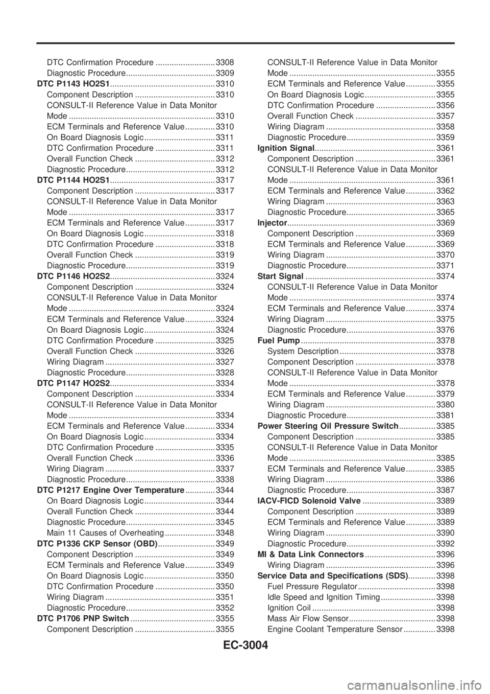
DTC Confirmation Procedure .......................... 3308
Diagnostic Procedure....................................... 3309
DTC P1143 HO2S1.............................................. 3310
Component Description ................................... 3310
CONSULT-II Reference Value in Data Monitor
Mode ................................................................ 3310
ECM Terminals and Reference Value ............. 3310
On Board Diagnosis Logic ............................... 3311
DTC Confirmation Procedure .......................... 3311
Overall Function Check ................................... 3312
Diagnostic Procedure....................................... 3312
DTC P1144 HO2S1.............................................. 3317
Component Description ................................... 3317
CONSULT-II Reference Value in Data Monitor
Mode ................................................................ 3317
ECM Terminals and Reference Value ............. 3317
On Board Diagnosis Logic ............................... 3318
DTC Confirmation Procedure .......................... 3318
Overall Function Check ................................... 3319
Diagnostic Procedure....................................... 3319
DTC P1146 HO2S2.............................................. 3324
Component Description ................................... 3324
CONSULT-II Reference Value in Data Monitor
Mode ................................................................ 3324
ECM Terminals and Reference Value ............. 3324
On Board Diagnosis Logic ............................... 3324
DTC Confirmation Procedure .......................... 3325
Overall Function Check ................................... 3326
Wiring Diagram ................................................ 3327
Diagnostic Procedure....................................... 3328
DTC P1147 HO2S2.............................................. 3334
Component Description ................................... 3334
CONSULT-II Reference Value in Data Monitor
Mode ................................................................ 3334
ECM Terminals and Reference Value ............. 3334
On Board Diagnosis Logic ............................... 3334
DTC Confirmation Procedure .......................... 3335
Overall Function Check ................................... 3336
Wiring Diagram ................................................ 3337
Diagnostic Procedure....................................... 3338
DTC P1217 Engine Over Temperature............. 3344
On Board Diagnosis Logic ............................... 3344
Overall Function Check ................................... 3344
Diagnostic Procedure....................................... 3345
Main 11 Causes of Overheating ...................... 3348
DTC P1336 CKP Sensor (OBD)......................... 3349
Component Description ................................... 3349
ECM Terminals and Reference Value ............. 3349
On Board Diagnosis Logic ............................... 3350
DTC Confirmation Procedure .......................... 3350
Wiring Diagram ................................................ 3351
Diagnostic Procedure....................................... 3352
DTC P1706 PNP Switch..................................... 3355
Component Description ................................... 3355CONSULT-II Reference Value in Data Monitor
Mode ................................................................ 3355
ECM Terminals and Reference Value ............. 3355
On Board Diagnosis Logic ............................... 3355
DTC Confirmation Procedure .......................... 3356
Overall Function Check ................................... 3357
Wiring Diagram ................................................ 3358
Diagnostic Procedure....................................... 3359
Ignition Signal..................................................... 3361
Component Description ................................... 3361
CONSULT-II Reference Value in Data Monitor
Mode ................................................................ 3361
ECM Terminals and Reference Value ............. 3362
Wiring Diagram ................................................ 3363
Diagnostic Procedure....................................... 3365
Injector................................................................. 3369
Component Description ................................... 3369
ECM Terminals and Reference Value ............. 3369
Wiring Diagram ................................................ 3370
Diagnostic Procedure....................................... 3371
Start Signal......................................................... 3374
CONSULT-II Reference Value in Data Monitor
Mode ................................................................ 3374
ECM Terminals and Reference Value ............. 3374
Wiring Diagram ................................................ 3375
Diagnostic Procedure....................................... 3376
Fuel Pump........................................................... 3378
System Description .......................................... 3378
Component Description ................................... 3378
CONSULT-II Reference Value in Data Monitor
Mode ................................................................ 3378
ECM Terminals and Reference Value ............. 3379
Wiring Diagram ................................................ 3380
Diagnostic Procedure....................................... 3381
Power Steering Oil Pressure Switch................ 3385
Component Description ................................... 3385
CONSULT-II Reference Value in Data Monitor
Mode ................................................................ 3385
ECM Terminals and Reference Value ............. 3385
Wiring Diagram ................................................ 3386
Diagnostic Procedure....................................... 3387
IACV-FICD Solenoid Valve................................ 3389
Component Description ................................... 3389
ECM Terminals and Reference Value ............. 3389
Wiring Diagram ................................................ 3390
Diagnostic Procedure....................................... 3392
MI & Data Link Connectors............................... 3396
Wiring Diagram ................................................ 3396
Service Data and Specifications (SDS)............ 3398
Fuel Pressure Regulator .................................. 3398
Idle Speed and Ignition Timing ........................ 3398
Ignition Coil ...................................................... 3398
Mass Air Flow Sensor...................................... 3398
Engine Coolant Temperature Sensor .............. 3398
EC-3004
Page 32 of 1306
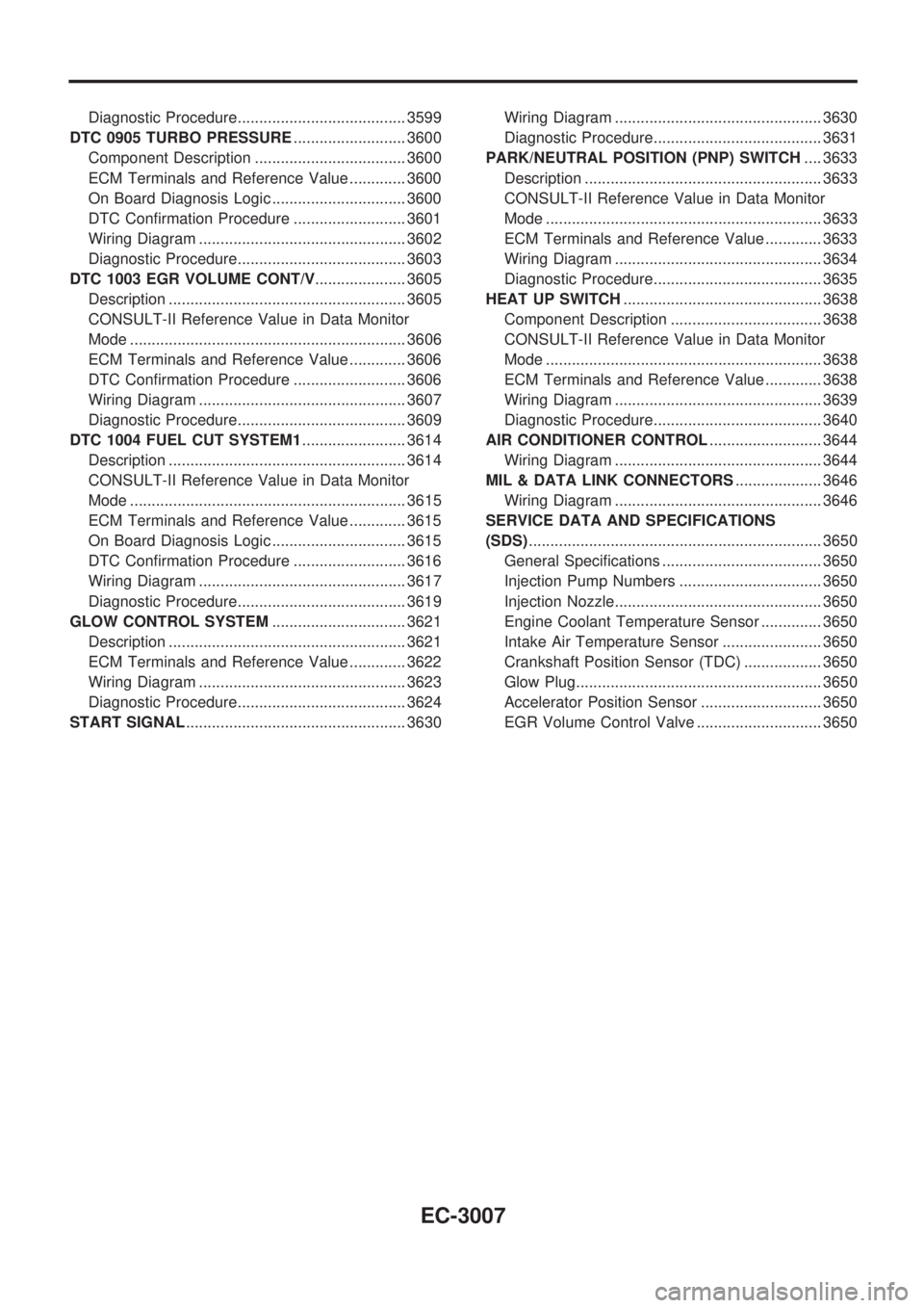
Diagnostic Procedure....................................... 3599
DTC 0905 TURBO PRESSURE.......................... 3600
Component Description ................................... 3600
ECM Terminals and Reference Value ............. 3600
On Board Diagnosis Logic ............................... 3600
DTC Confirmation Procedure .......................... 3601
Wiring Diagram ................................................ 3602
Diagnostic Procedure....................................... 3603
DTC 1003 EGR VOLUME CONT/V..................... 3605
Description ....................................................... 3605
CONSULT-II Reference Value in Data Monitor
Mode ................................................................ 3606
ECM Terminals and Reference Value ............. 3606
DTC Confirmation Procedure .......................... 3606
Wiring Diagram ................................................ 3607
Diagnostic Procedure....................................... 3609
DTC 1004 FUEL CUT SYSTEM1........................ 3614
Description ....................................................... 3614
CONSULT-II Reference Value in Data Monitor
Mode ................................................................ 3615
ECM Terminals and Reference Value ............. 3615
On Board Diagnosis Logic ............................... 3615
DTC Confirmation Procedure .......................... 3616
Wiring Diagram ................................................ 3617
Diagnostic Procedure....................................... 3619
GLOW CONTROL SYSTEM............................... 3621
Description ....................................................... 3621
ECM Terminals and Reference Value ............. 3622
Wiring Diagram ................................................ 3623
Diagnostic Procedure....................................... 3624
START SIGNAL................................................... 3630Wiring Diagram ................................................ 3630
Diagnostic Procedure....................................... 3631
PARK/NEUTRAL POSITION (PNP) SWITCH.... 3633
Description ....................................................... 3633
CONSULT-II Reference Value in Data Monitor
Mode ................................................................ 3633
ECM Terminals and Reference Value ............. 3633
Wiring Diagram ................................................ 3634
Diagnostic Procedure....................................... 3635
HEAT UP SWITCH.............................................. 3638
Component Description ................................... 3638
CONSULT-II Reference Value in Data Monitor
Mode ................................................................ 3638
ECM Terminals and Reference Value ............. 3638
Wiring Diagram ................................................ 3639
Diagnostic Procedure....................................... 3640
AIR CONDITIONER CONTROL.......................... 3644
Wiring Diagram ................................................ 3644
MIL & DATA LINK CONNECTORS.................... 3646
Wiring Diagram ................................................ 3646
SERVICE DATA AND SPECIFICATIONS
(SDS).................................................................... 3650
General Specifications ..................................... 3650
Injection Pump Numbers ................................. 3650
Injection Nozzle................................................ 3650
Engine Coolant Temperature Sensor .............. 3650
Intake Air Temperature Sensor ....................... 3650
Crankshaft Position Sensor (TDC) .................. 3650
Glow Plug......................................................... 3650
Accelerator Position Sensor ............................ 3650
EGR Volume Control Valve ............................. 3650
EC-3007
Page 41 of 1306
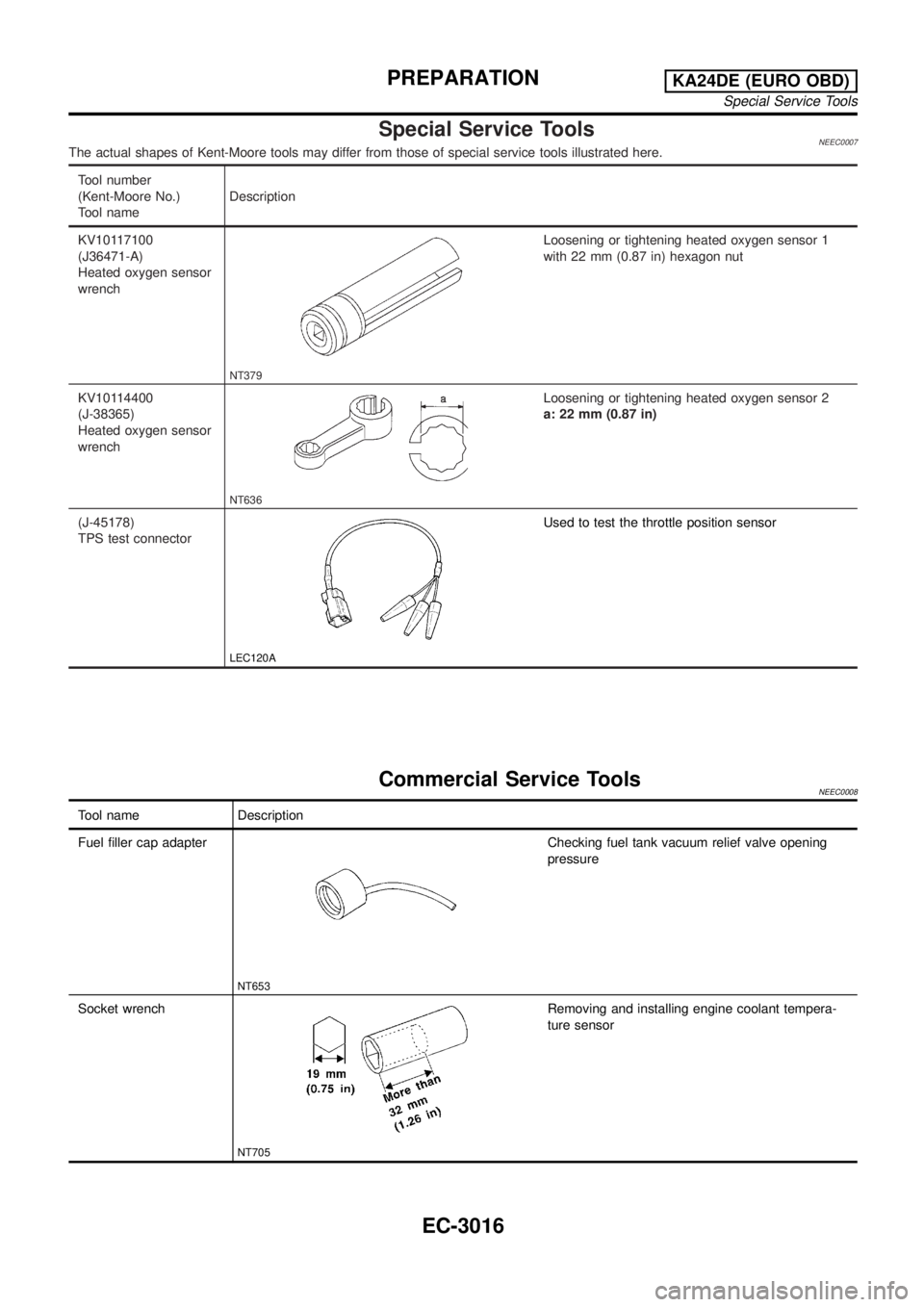
Special Service ToolsNEEC0007The actual shapes of Kent-Moore tools may differ from those of special service tools illustrated here.
Tool number
(Kent-Moore No.)
Tool nameDescription
KV10117100
(J36471-A)
Heated oxygen sensor
wrench
NT379
Loosening or tightening heated oxygen sensor 1
with 22 mm (0.87 in) hexagon nut
KV10114400
(J-38365)
Heated oxygen sensor
wrench
NT636
Loosening or tightening heated oxygen sensor 2
a: 22 mm (0.87 in)
(J-45178)
TPS test connector
LEC120A
Used to test the throttle position sensor
Commercial Service ToolsNEEC0008
Tool name Description
Fuel filler cap adapter
NT653
Checking fuel tank vacuum relief valve opening
pressure
Socket wrench
NT705
Removing and installing engine coolant tempera-
ture sensor
PREPARATIONKA24DE (EURO OBD)
Special Service Tools
EC-3016
Page 48 of 1306
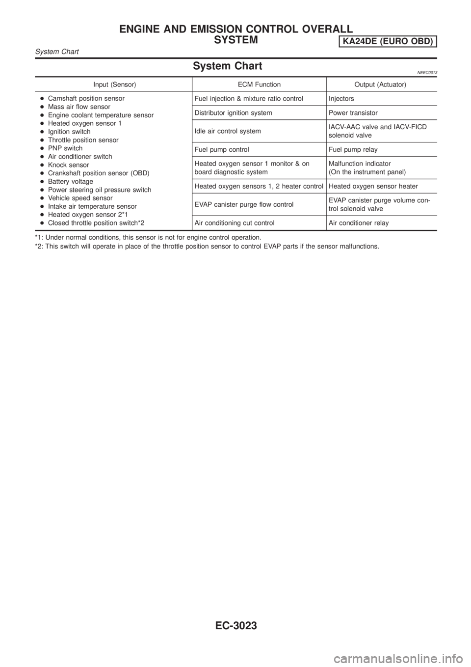
System ChartNEEC0013
Input (Sensor) ECM Function Output (Actuator)
+Camshaft position sensor
+Mass air flow sensor
+Engine coolant temperature sensor
+Heated oxygen sensor 1
+Ignition switch
+Throttle position sensor
+PNP switch
+Air conditioner switch
+Knock sensor
+Crankshaft position sensor (OBD)
+Battery voltage
+Power steering oil pressure switch
+Vehicle speed sensor
+Intake air temperature sensor
+Heated oxygen sensor 2*1
+Closed throttle position switch*2Fuel injection & mixture ratio control Injectors
Distributor ignition system Power transistor
Idle air control systemIACV-AAC valve and IACV-FICD
solenoid valve
Fuel pump control Fuel pump relay
Heated oxygen sensor 1 monitor & on
board diagnostic systemMalfunction indicator
(On the instrument panel)
Heated oxygen sensors 1, 2 heater control Heated oxygen sensor heater
EVAP canister purge flow controlEVAP canister purge volume con-
trol solenoid valve
Air conditioning cut control Air conditioner relay
*1: Under normal conditions, this sensor is not for engine control operation.
*2: This switch will operate in place of the throttle position sensor to control EVAP parts if the sensor malfunctions.
ENGINE AND EMISSION CONTROL OVERALL
SYSTEM
KA24DE (EURO OBD)
System Chart
EC-3023
Page 49 of 1306

Multiport Fuel Injection (MFI) System
DESCRIPTIONNEEC0014Input/Output Signal ChartNEEC0014S01
Sensor Input Signal to ECMECM func-
tionActuator
Camshaft position sensor Engine speed and piston position
Fuel injec-
tion & mix-
ture ratio
controlInjector Mass air flow sensor Amount of intake air
Engine coolant temperature sensor Engine coolant temperature
Heated oxygen sensor 1 Density of oxygen in exhaust gas
Throttle position sensorThrottle position
Throttle valve idle position
PNP switch Gear position
Vehicle speed sensor Vehicle speed
Ignition switch Start signal
Air conditioner switch Air conditioner operation
Knock sensor Engine knocking condition
Battery Battery voltage
Power steering oil pressure switch Power steering operation
Heated oxygen sensor 2* Density of oxygen in exhaust gas
* Under normal conditions, this sensor is not for engine control operation.
Basic Multiport Fuel Injection SystemNEEC0014S02The amount of fuel injected from the fuel injector is determined by the ECM. The ECM controls the length of
time the valve remains open (injection pulse duration). The amount of fuel injected is a program value in the
ECM memory. The program value is preset by engine operating conditions. These conditions are determined
by input signals (for engine speed and intake air) from both the camshaft position sensor and the mass air
flow sensor.
Various Fuel Injection Increase/Decrease CompensationNEEC0014S03In addition, the amount of fuel injected is compensated to improve engine performance under various oper-
ating conditions as listed below.
+During warm-up
+When starting the engine
+During acceleration
+Hot-engine operation
+High-load, high-speed operation
+During deceleration
+During high engine speed operation
ENGINE AND EMISSION BASIC CONTROL SYSTEM
DESCRIPTION
KA24DE (EURO OBD)
Multiport Fuel Injection (MFI) System
EC-3024
Page 53 of 1306

Air Conditioning Cut Control
DESCRIPTION=NEEC0016Input/Output Signal ChartNEEC0016S01
Sensor Input Signal to ECMECM func-
tionActuator
Air conditioner switch Air conditioner ªONº signal
Air condi-
tioner cut
controlAir conditioner relay Throttle position sensor Throttle valve opening angle
Camshaft position sensor Engine speed
Engine coolant temperature sensor Engine coolant temperature
Ignition switch Start signal
Vehicle speed sensor Vehicle speed
Power steering oil pressure switch Power steering operation
System DescriptionNEEC0016S02This system improves engine operation when the air conditioner is used.
Under the following conditions, the air conditioner is turned off.
+When the accelerator pedal is fully depressed.
+When cranking the engine.
+When the engine coolant temperature becomes excessively high.
+When operating power steering and air conditioner during low engine speed or when fully releasing accel-
erator pedal.
+When engine speed is excessively low.
Fuel Cut Control (at no load & high engine
speed)
DESCRIPTIONNEEC0017Input/Output Signal ChartNEEC0017S01
Sensor Input Signal to ECMECM func-
tionActuator
Vehicle speed sensor Vehicle speed
Fuel cut
controlInjectors PNP switch Neutral position
Throttle position sensor Throttle position
Camshaft position sensor Engine speed
If the engine speed is above 3,000 rpm with no load, (for example, in Neutral and engine speed over 3,000
rpm) fuel will be cut off after some time. The exact time when the fuel is cut off varies based on engine speed.
Fuel cut will operate until the engine speed reaches 1,500 rpm, then fuel cut is cancelled.
NOTE:
This function is different from deceleration control listed under ªMultiport Fuel Injection (MFI) Systemº,
EC-3024.
ENGINE AND EMISSION BASIC CONTROL SYSTEM
DESCRIPTION
KA24DE (EURO OBD)
Air Conditioning Cut Control
EC-3028
Page 55 of 1306
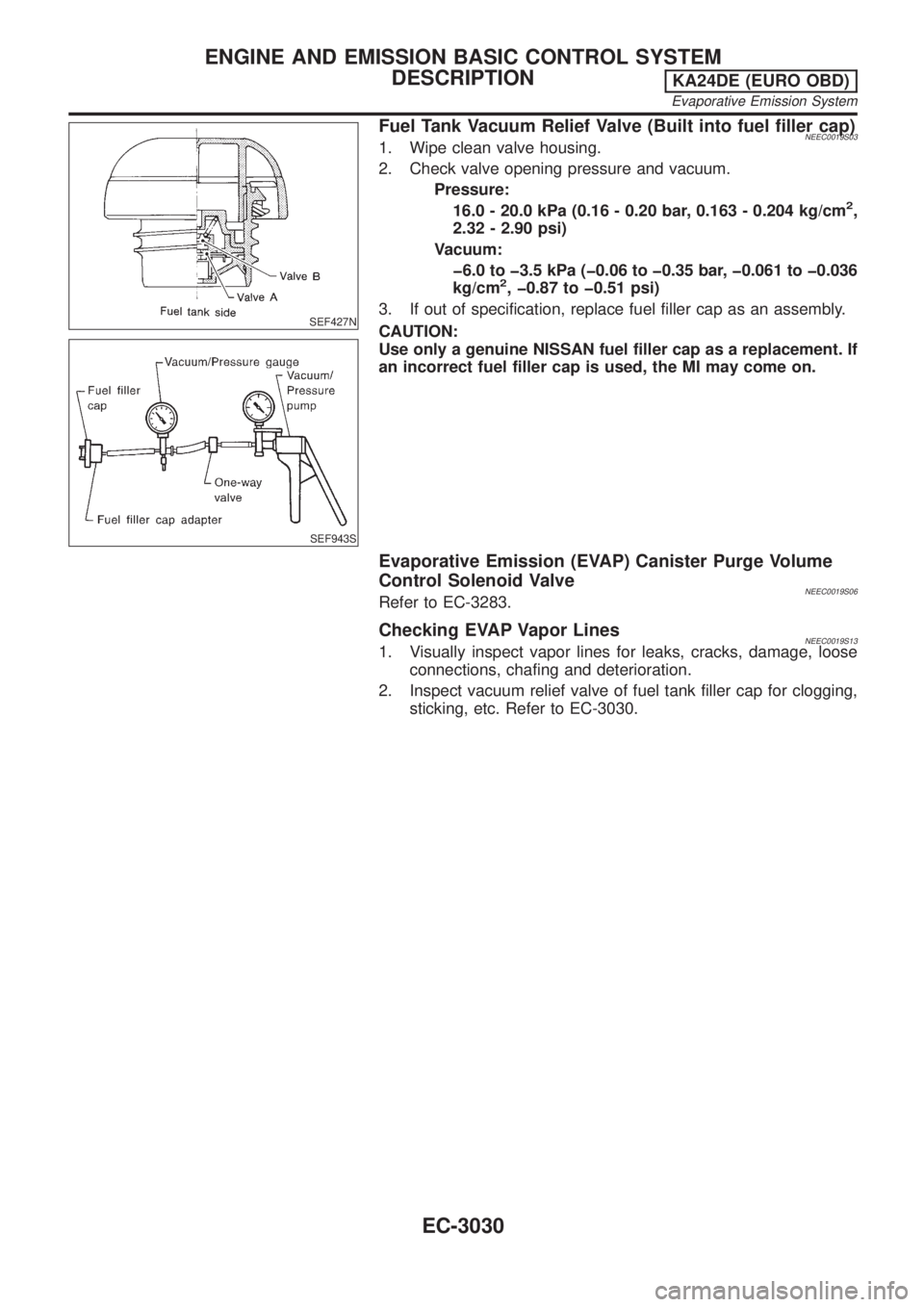
SEF427N
SEF943S
Fuel Tank Vacuum Relief Valve (Built into fuel filler cap)NEEC0019S031. Wipe clean valve housing.
2. Check valve opening pressure and vacuum.
Pressure:
16.0 - 20.0 kPa (0.16 - 0.20 bar, 0.163 - 0.204 kg/cm
2,
2.32 - 2.90 psi)
Vacuum:
þ6.0 to þ3.5 kPa (þ0.06 to þ0.35 bar, þ0.061 to þ0.036
kg/cm
2, þ0.87 to þ0.51 psi)
3. If out of specification, replace fuel filler cap as an assembly.
CAUTION:
Use only a genuine NISSAN fuel filler cap as a replacement. If
an incorrect fuel filler cap is used, the MI may come on.
Evaporative Emission (EVAP) Canister Purge Volume
Control Solenoid Valve
NEEC0019S06Refer to EC-3283.
Checking EVAP Vapor LinesNEEC0019S131. Visually inspect vapor lines for leaks, cracks, damage, loose
connections, chafing and deterioration.
2. Inspect vacuum relief valve of fuel tank filler cap for clogging,
sticking, etc. Refer to EC-3030.
ENGINE AND EMISSION BASIC CONTROL SYSTEM
DESCRIPTION
KA24DE (EURO OBD)
Evaporative Emission System
EC-3030