2001 NISSAN PICK-UP fuel pressure
[x] Cancel search: fuel pressurePage 425 of 1306
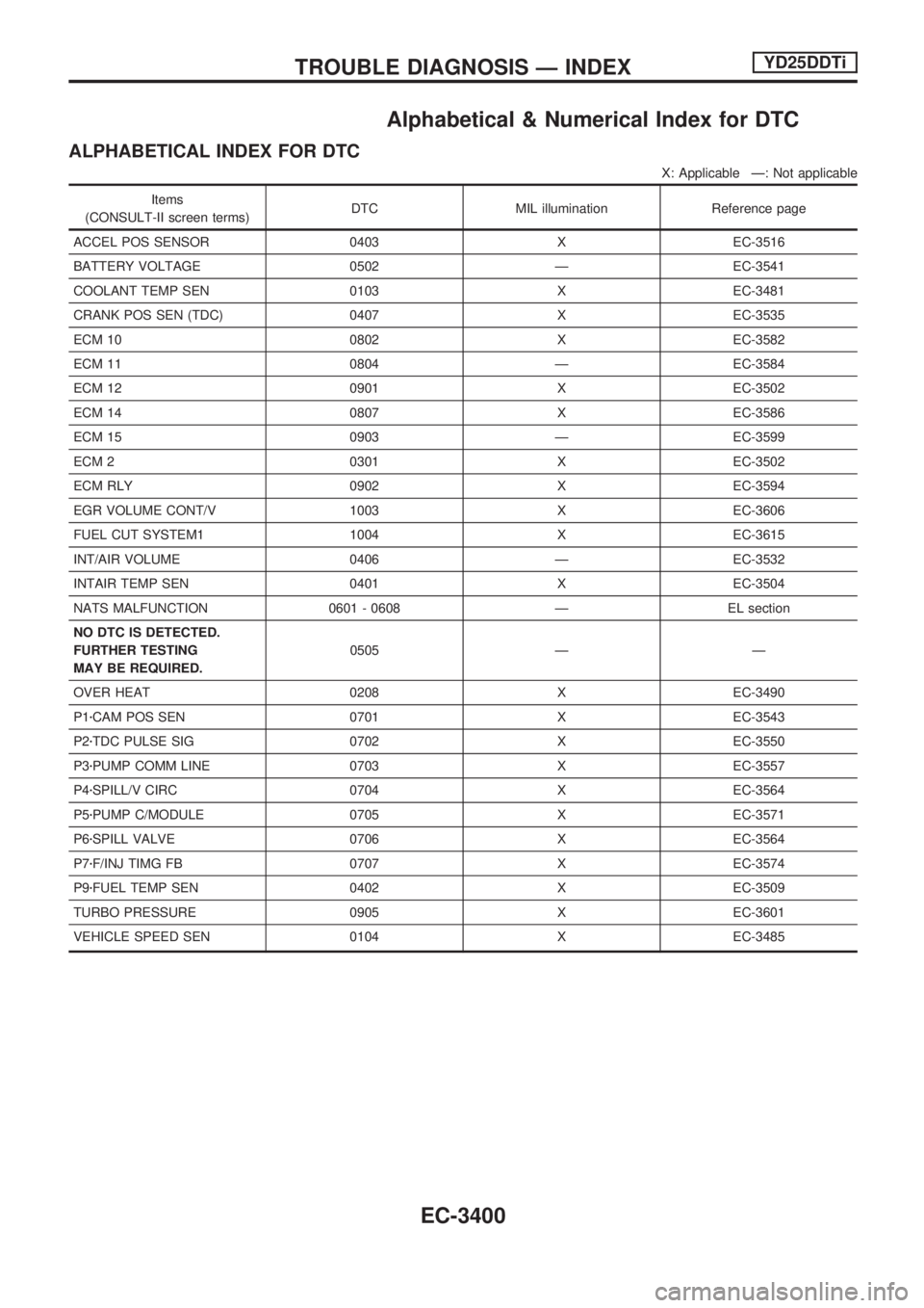
Alphabetical & Numerical Index for DTC
ALPHABETICAL INDEX FOR DTC
X: Applicable Ð: Not applicable
Items
(CONSULT-II screen terms)DTC MIL illumination Reference page
ACCEL POS SENSOR 0403 X EC-3516
BATTERY VOLTAGE 0502 Ð EC-3541
COOLANT TEMP SEN 0103 X EC-3481
CRANK POS SEN (TDC) 0407 X EC-3535
ECM 10 0802 X EC-3582
ECM 11 0804 Ð EC-3584
ECM 12 0901 X EC-3502
ECM 14 0807 X EC-3586
ECM 15 0903 Ð EC-3599
ECM 2 0301 X EC-3502
ECM RLY 0902 X EC-3594
EGR VOLUME CONT/V 1003 X EC-3606
FUEL CUT SYSTEM1 1004 X EC-3615
INT/AIR VOLUME 0406 Ð EC-3532
INTAIR TEMP SEN 0401 X EC-3504
NATS MALFUNCTION 0601 - 0608 Ð EL section
NO DTC IS DETECTED.
FURTHER TESTING
MAY BE REQUIRED.0505 Ð Ð
OVER HEAT 0208 X EC-3490
P1zCAM POS SEN 0701 X EC-3543
P2zTDC PULSE SIG 0702 X EC-3550
P3zPUMP COMM LINE 0703 X EC-3557
P4zSPILL/V CIRC 0704 X EC-3564
P5zPUMP C/MODULE 0705 X EC-3571
P6zSPILL VALVE 0706 X EC-3564
P7zF/INJ TIMG FB 0707 X EC-3574
P9zFUEL TEMP SEN 0402 X EC-3509
TURBO PRESSURE 0905 X EC-3601
VEHICLE SPEED SEN 0104 X EC-3485
TROUBLE DIAGNOSIS Ð INDEXYD25DDTi
EC-3400
Page 426 of 1306
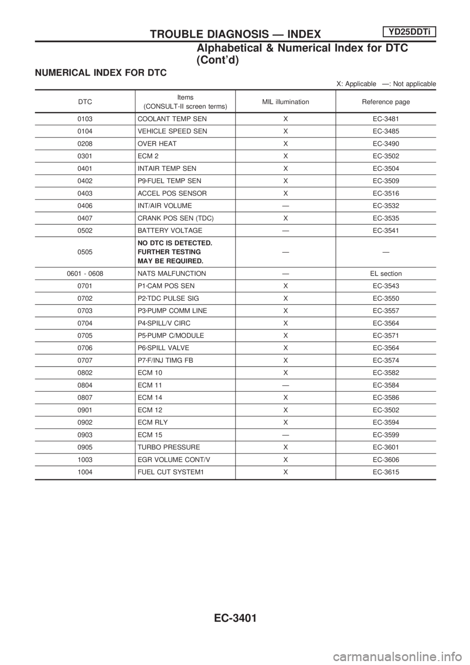
NUMERICAL INDEX FOR DTC
X: Applicable Ð: Not applicable
DTCItems
(CONSULT-II screen terms)MIL illumination Reference page
0103 COOLANT TEMP SEN X EC-3481
0104 VEHICLE SPEED SEN X EC-3485
0208 OVER HEAT X EC-3490
0301 ECM 2 X EC-3502
0401 INTAIR TEMP SEN X EC-3504
0402 P9zFUEL TEMP SEN X EC-3509
0403 ACCEL POS SENSOR X EC-3516
0406 INT/AIR VOLUME Ð EC-3532
0407 CRANK POS SEN (TDC) X EC-3535
0502 BATTERY VOLTAGE Ð EC-3541
0505NO DTC IS DETECTED.
FURTHER TESTING
MAY BE REQUIRED.ÐÐ
0601 - 0608 NATS MALFUNCTION Ð EL section
0701 P1zCAM POS SEN X EC-3543
0702 P2zTDC PULSE SIG X EC-3550
0703 P3zPUMP COMM LINE X EC-3557
0704 P4zSPILL/V CIRC X EC-3564
0705 P5zPUMP C/MODULE X EC-3571
0706 P6zSPILL VALVE X EC-3564
0707 P7zF/INJ TIMG FB X EC-3574
0802 ECM 10 X EC-3582
0804 ECM 11 Ð EC-3584
0807 ECM 14 X EC-3586
0901 ECM 12 X EC-3502
0902 ECM RLY X EC-3594
0903 ECM 15 Ð EC-3599
0905 TURBO PRESSURE X EC-3601
1003 EGR VOLUME CONT/V X EC-3606
1004 FUEL CUT SYSTEM1 X EC-3615
TROUBLE DIAGNOSIS Ð INDEXYD25DDTi
Alphabetical & Numerical Index for DTC
(Cont'd)
EC-3401
Page 435 of 1306
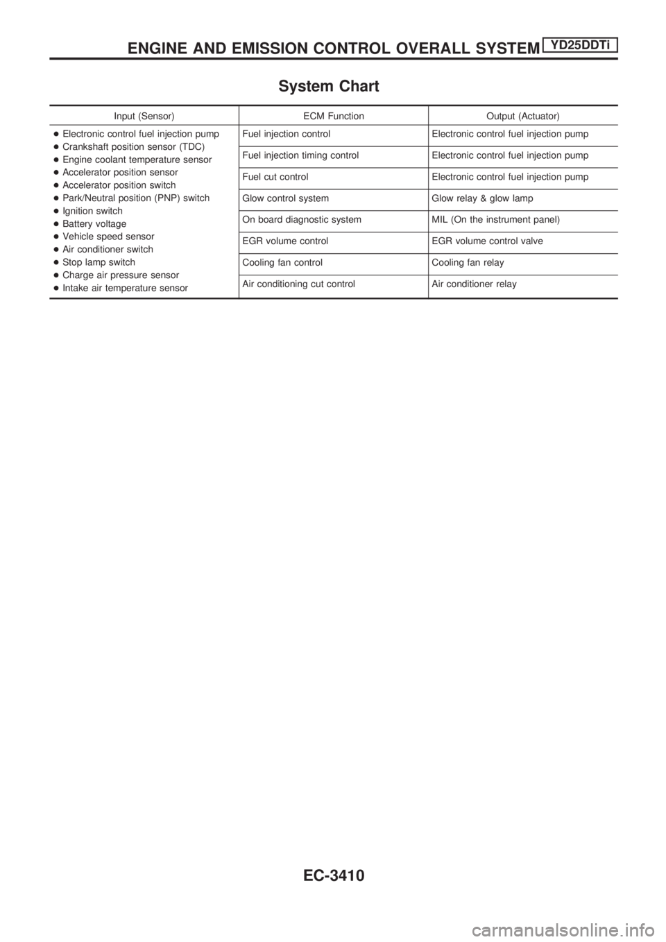
System Chart
Input (Sensor) ECM Function Output (Actuator)
+Electronic control fuel injection pump
+Crankshaft position sensor (TDC)
+Engine coolant temperature sensor
+Accelerator position sensor
+Accelerator position switch
+Park/Neutral position (PNP) switch
+Ignition switch
+Battery voltage
+Vehicle speed sensor
+Air conditioner switch
+Stop lamp switch
+Charge air pressure sensor
+Intake air temperature sensorFuel injection control Electronic control fuel injection pump
Fuel injection timing control Electronic control fuel injection pump
Fuel cut control Electronic control fuel injection pump
Glow control system Glow relay & glow lamp
On board diagnostic system MIL (On the instrument panel)
EGR volume control EGR volume control valve
Cooling fan control Cooling fan relay
Air conditioning cut control Air conditioner relay
ENGINE AND EMISSION CONTROL OVERALL SYSTEMYD25DDTi
EC-3410
Page 442 of 1306
Spill Tube
Removal
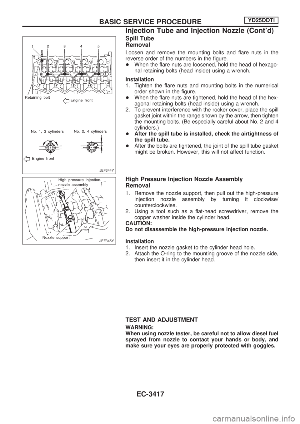
Loosen and remove the mounting bolts and flare nuts in the
reverse order of the numbers in the figure.
+When the flare nuts are loosened, hold the head of hexago-
nal retaining bolts (head inside) using a wrench.
Installation
1. Tighten the flare nuts and mounting bolts in the numerical
order shown in the figure.
+When the flare nuts are tightened, hold the head of the hex-
agonal retaining bolts (head inside) using a wrench.
2. To prevent interference with the rocker cover, place the spill
gasket joint within the range shown by the arrow, then tighten
the mounting bolts. (Be especially careful about No. 2 and 4
cylinders.)
+After the spill tube is installed, check the airtightness of
the spill tube.
+After the bolts are tightened, the joint of the spill tube gasket
might be broken. However, this will not affect function.
High Pressure Injection Nozzle Assembly
Removal
1. Remove the nozzle support, then pull out the high-pressure
injection nozzle assembly by turning it clockwise/
counterclockwise.
2. Using a tool such as a flat-head screwdriver, remove the
copper washer inside the cylinder head.
CAUTION:
Do not disassemble the high-pressure injection nozzle.
Installation
1. Insert the nozzle gasket to the cylinder head hole.
2. Attach the O-ring to the mounting groove of the nozzle side,
then insert it in the cylinder head.
TEST AND ADJUSTMENT
WARNING:
When using nozzle tester, be careful not to allow diesel fuel
sprayed from nozzle to contact your hands or body, and
make sure your eyes are properly protected with goggles.
JEF344Y
JEF345Y
BASIC SERVICE PROCEDUREYD25DDTi
Injection Tube and Injection Nozzle (Cont'd)
EC-3417
Page 443 of 1306
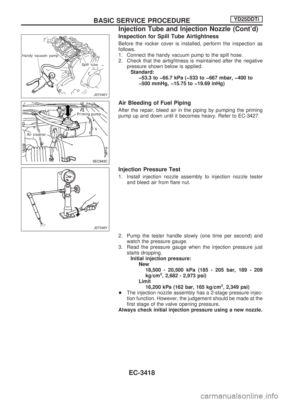
Inspection for Spill Tube Airtightness
Before the rocker cover is installed, perform the inspection as
follows.
1. Connect the handy vacuum pump to the spill hose.
2. Check that the airtightness is maintained after the negative
pressure shown below is applied.
Standard:
þ53.3 to þ66.7 kPa (þ533 to þ667 mbar, þ400 to
þ500 mmHg, þ15.75 to þ19.69 inHg)
Air Bleeding of Fuel Piping
After the repair, bleed air in the piping by pumping the priming
pump up and down until it becomes heavy. Refer to EC-3427.
Injection Pressure Test
1. Install injection nozzle assembly to injection nozzle tester
and bleed air from flare nut.
2. Pump the tester handle slowly (one time per second) and
watch the pressure gauge.
3. Read the pressure gauge when the injection pressure just
starts dropping.
Initial injection pressure:
New
18,500 - 20,500 kPa (185 - 205 bar, 189 - 209
kg/cm
2, 2,682 - 2,973 psi)
Limit
16,200 kPa (162 bar, 165 kg/cm
2, 2,349 psi)
+The injection nozzle assembly has a 2-stage pressure injec-
tion function. However, the judgement should be made at the
first stage of the valve opening pressure.
Always check initial injection pressure using a new nozzle.
JEF346Y
SEC943C
JEF348Y
BASIC SERVICE PROCEDUREYD25DDTi
Injection Tube and Injection Nozzle (Cont'd)
EC-3418
Page 460 of 1306
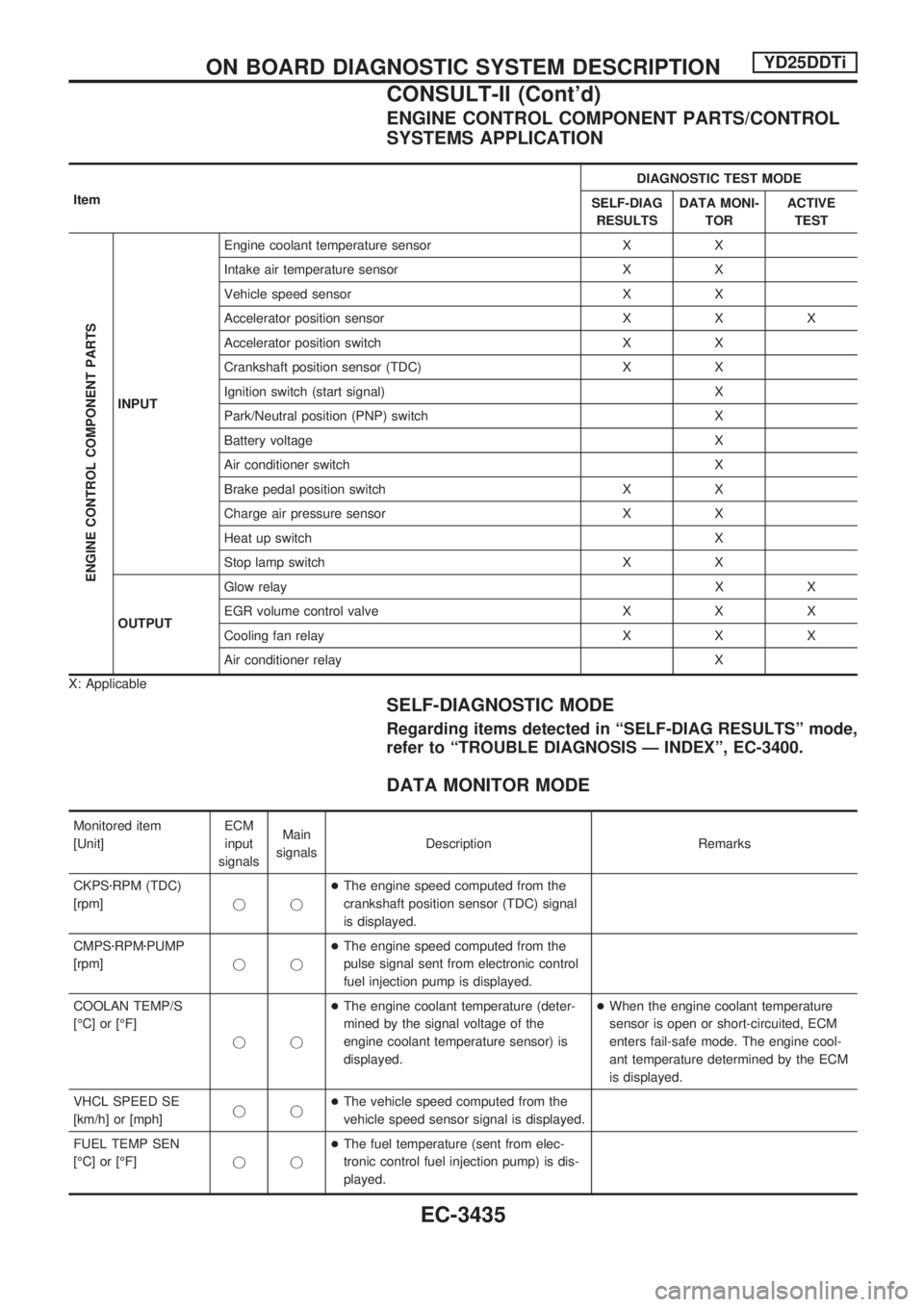
ENGINE CONTROL COMPONENT PARTS/CONTROL
SYSTEMS APPLICATION
ItemDIAGNOSTIC TEST MODE
SELF-DIAG
RESULTSDATA MONI-
TORACTIVE
TEST
ENGINE CONTROL COMPONENT PARTS
INPUTEngine coolant temperature sensor X X
Intake air temperature sensor X X
Vehicle speed sensor X X
Accelerator position sensor X X X
Accelerator position switch X X
Crankshaft position sensor (TDC) X X
Ignition switch (start signal) X
Park/Neutral position (PNP) switch X
Battery voltage X
Air conditioner switch X
Brake pedal position switch X X
Charge air pressure sensor X X
Heat up switch X
Stop lamp switch X X
OUTPUTGlow relayXX
EGR volume control valve X X X
Cooling fan relay X X X
Air conditioner relay X
X: Applicable
SELF-DIAGNOSTIC MODE
Regarding items detected in ªSELF-DIAG RESULTSº mode,
refer to ªTROUBLE DIAGNOSIS Ð INDEXº, EC-3400.
DATA MONITOR MODE
Monitored item
[Unit]ECM
input
signalsMain
signalsDescription Remarks
CKPSzRPM (TDC)
[rpm]jj+The engine speed computed from the
crankshaft position sensor (TDC) signal
is displayed.
CMPSzRPMzPUMP
[rpm]jj+The engine speed computed from the
pulse signal sent from electronic control
fuel injection pump is displayed.
COOLAN TEMP/S
[ÉC] or [ÉF]
jj+The engine coolant temperature (deter-
mined by the signal voltage of the
engine coolant temperature sensor) is
displayed.+When the engine coolant temperature
sensor is open or short-circuited, ECM
enters fail-safe mode. The engine cool-
ant temperature determined by the ECM
is displayed.
VHCL SPEED SE
[km/h] or [mph]jj+The vehicle speed computed from the
vehicle speed sensor signal is displayed.
FUEL TEMP SEN
[ÉC] or [ÉF]jj+The fuel temperature (sent from elec-
tronic control fuel injection pump) is dis-
played.
ON BOARD DIAGNOSTIC SYSTEM DESCRIPTIONYD25DDTi
CONSULT-II (Cont'd)
EC-3435
Page 461 of 1306
![NISSAN PICK-UP 2001 Repair Manual Monitored item
[Unit]ECM
input
signalsMain
signalsDescription Remarks
ACCEL POS SEN [V]
jj+The accelerator position sensor signal
voltage is displayed.
FULL ACCEL SW
[ON/OFF]jj+Indicates [ON/OFF] cond NISSAN PICK-UP 2001 Repair Manual Monitored item
[Unit]ECM
input
signalsMain
signalsDescription Remarks
ACCEL POS SEN [V]
jj+The accelerator position sensor signal
voltage is displayed.
FULL ACCEL SW
[ON/OFF]jj+Indicates [ON/OFF] cond](/manual-img/5/57372/w960_57372-460.png)
Monitored item
[Unit]ECM
input
signalsMain
signalsDescription Remarks
ACCEL POS SEN [V]
jj+The accelerator position sensor signal
voltage is displayed.
FULL ACCEL SW
[ON/OFF]jj+Indicates [ON/OFF] condition from the
accelerator position switch signal.
OFF ACCEL SW
[ON/OFF]jj+Indicates [ON/OFF] condition from the
accelerator position switch signal.
SPILL/V [ÉCA]
j+The control position of spill valve (sent
from electronic control fuel injection
pump) is displayed.
BATTERY VOLT [V]
jj+The power supply voltage of ECM is dis-
played.
I/C INT/A T/S [V]
jj+The signal voltage of the intake air tem-
perature sensor is displayed.
P/N POSI SW
[ON/OFF]jj+Indicates [ON/OFF] condition from the
park/neutral position switch signal.
START SIGNAL
[ON/OFF]jj+Indicates [ON/OFF] condition from the
starter signal.+After starting the engine, [OFF] is dis-
played regardless of the starter signal.
AIR COND SIG
[ON/OFF]jj+Indicates [ON/OFF] condition of the air
conditioner switch as determined by the
air conditioner signal.
BRAKE SW [ON/OFF]
jj+Indicates [ON/OFF] condition from the
stop lamp switch signal.
BRAKE SW2
[ON/OFF]jj+Indicates [ON/OFF] condition from the
brake pedal position switch.
IGN SW
[ON/OFF]jj+Indicates [ON/OFF] condition from igni-
tion switch signal.
WARM UP SW
[ON/OFF]j+Indicates [ON/OFF] condition from the
heat up switch signal.
TURBO BST SEN
[kPa]j+The charge air pressure (determined by
the signal voltage sent to the ECM) is
displayed.
DECELER F/CUT
[ON/OFF]j+The [ON/OFF] condition from decelera-
tion fuel cut signal (sent from ECM) is
displayed.
INJ TIMG C/V [%]
j+The duty ratio of fuel injection timing
control valve (sent from electronic con-
trol fuel injection pump) is displayed.
AIR COND RLY
[ON/OFF]j+Indicates the control condition of the air
conditioner relay (determined by ECM
according to the input signals).
GLOW RLY [ON/OFF]
j+The glow relay control condition (deter-
mined by ECM according to the input
signal) is displayed.
COOLING FAN
[ON/OFF]
j+Indicates the control condition of the
cooling fans (determined by ECM
according to the input signal).
+ON ... Operates.
OFF ... Stopped.
ON BOARD DIAGNOSTIC SYSTEM DESCRIPTIONYD25DDTi
CONSULT-II (Cont'd)
EC-3436
Page 462 of 1306
![NISSAN PICK-UP 2001 Repair Manual Monitored item
[Unit]ECM
input
signalsMain
signalsDescription Remarks
EGR VOL CON/V
[step]
j+Indicates the EGR volume control value
computed by the ECM according to the
input signals.
+The opening bec NISSAN PICK-UP 2001 Repair Manual Monitored item
[Unit]ECM
input
signalsMain
signalsDescription Remarks
EGR VOL CON/V
[step]
j+Indicates the EGR volume control value
computed by the ECM according to the
input signals.
+The opening bec](/manual-img/5/57372/w960_57372-461.png)
Monitored item
[Unit]ECM
input
signalsMain
signalsDescription Remarks
EGR VOL CON/V
[step]
j+Indicates the EGR volume control value
computed by the ECM according to the
input signals.
+The opening becomes larger as the
value increases.
BARO SEN [kPa]
j+The barometric pressure (determined by
the signal voltage from the barometric
pressure sensor built into the ECM) is
displayed.
NOTE:
Any monitored item that does not match the vehicle being diagnosed is deleted from the display automatically.
ACTIVE TEST MODE
TEST ITEM CONDITION JUDGEMENT CHECK ITEM (REMEDY)
COOLING FAN+Ignition switch: ON
+Turn cooling fan ªONº and ªOFFº
using CONSULT-II.Cooling fan moves and stops.+Harness and connector
+Cooling fan motor
+Cooling fan relay
OFF ACCEL PO
SIG+Clears the self-learning fully closed accelerator position, detected by accelerator position sensor, from the
ECM.
GLOW RLY+Ignition switch: ON (Engine
stopped)
+Turn the glow relay ªONº and
ªOFFº using CONSULT-II and
listen to operating sound.Glow relay makes the operating
sound.+Harness and connector
+Glow relay
INJ TIMING*1+Engine: Return to the original
trouble condition
+Retard the injection timing using
CONSULT-II.If trouble symptom disappears, see
CHECK ITEM.+Electronic control fuel injection
pump
EGR VOL CONT/V+Ignition switch: ON
+Change EGR volume control
valve opening step using CON-
SULT-II.EGR volume control valve makes
an operating sound.+Harness and connector
+EGR volume control valve
*1: When using this item, DTC 0707 ªP7zF/INJ TIMG FBº may be detected. If so, erase it because it is not a malfunction.
ON BOARD DIAGNOSTIC SYSTEM DESCRIPTIONYD25DDTi
CONSULT-II (Cont'd)
EC-3437