2001 NISSAN PICK-UP maintenance
[x] Cancel search: maintenancePage 1 of 1306

GENERAL INFORMATIONGI
MAINTENANCEMA
ENGINE MECHANICALEM
ENGINE LUBRICATION &
COOLING SYSTEMSLC
ENGINE CONTROL SYSTEMEC
ACCELERATOR CONTROL, FUEL &
EXHAUST SYSTEMSFE
CLUTCHCL
MANUAL TRANSAXLEMT
TRANSFERTF
PROPELLER SHAFT &
DIFFERENTIAL CARRIERPD
FRONT AXLE & FRONT SUSPENSIONFA
REAR AXLE & REAR SUSPENSIONRA
BRAKE SYSTEMBR
STEERING SYSTEMST
RESTRAINT SYSTEMRS
BODY & TRIMBT
HEATER & AIR CONDITIONERHA
ELECTRICAL SYSTEMEL
ALPHABETICAL INDEXIDX
PICKUP
MODEL D22 SERIES
FOREWORD
This supplement contains informa-
tion concerning necessary service
procedures and relevant data for the
model D22 series.
All information, illustrations and spe-
ci®cations contained in this supple-
ment are based on the latest product
information available at the time of
publication. If your NISSAN model
differs from the speci®cations contain-
ed in this supplement, consult your
NISSAN distributor for information.
The right is reserved to make chan-
ges in speci®cations and methods at
any time without notice.
Edition: November 2001
Printing: November 2001 (01)
Publication No.: SM1E-D22CE0E
NISSAN EUROPE S.A.S.
2001 NISSAN EUROPE S.A.S. Printed in the Netherlands
Not to be reproduced in whole or in part without the prior written permission of Nissan Europe S.A.S., Paris, France.
QUICK REFERENCE INDEX
Page 2 of 1306
FOREWORD
This manual contains maintenance and repair procedures for NISSAN
PICKUP, model D22 series.
In order to assure your safety and the efficient functioning of the vehicle,
this manual should be read thoroughly. It is especially important that the
PRECAUTIONS in the GI section be completely understood before starting
any repair task.
All information in this manual is based on the latest product information
at the time of publication. The right is reserved to make changes in speci-
®cations and methods at any time without notice.
IMPORTANT SAFETY NOTICE
The proper performance of service is essential for both the safety of the
technician and the efficient functioning of the vehicle.
The service methods in this Service Manual are described in such a man-
ner that the service may be performed safely and accurately.
Service varies with the procedures used, the skills of the technician and the
tools and parts available. Accordingly, anyone using service procedures,
tools or parts which are not speci®cally recommended by NISSAN must
®rst completely satisfy himself that neither his safety nor the vehicle's
safety will be jeopardized by the service method selected.
NISSAN EUROPE S.A.S.
Service Engineering Section
Paris, France
Page 33 of 1306
Special Service Tool (YD25DDTi)
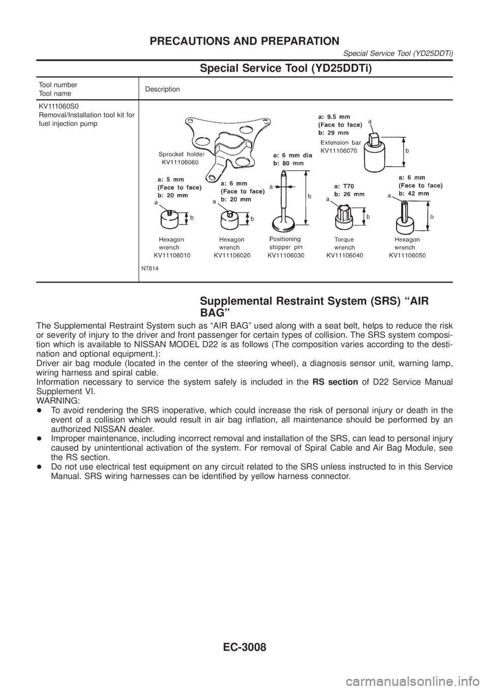
Tool number
Tool nameDescription
KV111060S0
Removal/Installation tool kit for
fuel injection pump
NT814
Supplemental Restraint System (SRS) ªAIR
BAGº
The Supplemental Restraint System such as ªAIR BAGº used along with a seat belt, helps to reduce the risk
or severity of injury to the driver and front passenger for certain types of collision. The SRS system composi-
tion which is available to NISSAN MODEL D22 is as follows (The composition varies according to the desti-
nation and optional equipment.):
Driver air bag module (located in the center of the steering wheel), a diagnosis sensor unit, warning lamp,
wiring harness and spiral cable.
Information necessary to service the system safely is included in theRS sectionof D22 Service Manual
Supplement VI.
WARNING:
+To avoid rendering the SRS inoperative, which could increase the risk of personal injury or death in the
event of a collision which would result in air bag inflation, all maintenance should be performed by an
authorized NISSAN dealer.
+Improper maintenance, including incorrect removal and installation of the SRS, can lead to personal injury
caused by unintentional activation of the system. For removal of Spiral Cable and Air Bag Module, see
the RS section.
+Do not use electrical test equipment on any circuit related to the SRS unless instructed to in this Service
Manual. SRS wiring harnesses can be identified by yellow harness connector.
PRECAUTIONS AND PREPARATION
Special Service Tool (YD25DDTi)
EC-3008
Page 37 of 1306
Supplemental Restraint System (SRS) ªAIR
BAGº and ªSEAT BELT PRE-TENSIONERº
NEEC0002The Supplemental Restraint System such as ªAIR BAGº and ªSEAT BELT PRE-TENSIONERº used along with
a seat belt, helps to reduce the risk or severity of injury to the driver and front passenger in a frontal collision.
The SRS system composition which is available to NISSAN MODEL D22 is as follows (The composition var-
ies according to the destination and optional equipment.):
Driver air bag module (located in the center of the steering wheel), front passenger air bag module (located
on the instrument panel on passenger side), seat belt pre-tensioner, a diagnosis sensor unit, warning lamp,
wiring harness and spiral cable.
Information necessary to service the system safely is included in theRS sectionof this Service Manual.
WARNING:
+To avoid rendering the SRS inoperative, which could increase the risk of personal injury or death
in the event of a collision which would result in air bag inflation, all maintenance must be performed
by an authorized NISSAN dealer.
+Improper maintenance, including incorrect removal and installation of the SRS, can lead to per-
sonal injury caused by unintentional activation of the system. For removal of Spiral Cable and Air
Bag Module, see the RS section.
+Do not use electrical test equipment on any circuit related to the SRS unless instructed to in this
Service Manual. SRS wiring harnesses can be identified by yellow harness connector.
Precautions for On Board Diagnostic (OBD)
System of Engine
NEEC0003The ECM has an on board diagnostic system. It will light up the malfunction indicator (MI) to warn the driver
of a malfunction causing emission deterioration.
CAUTION:
+Be sure to turn the ignition switch OFF and disconnect the negative battery terminal before any
repair or inspection work. The open/short circuit of related switches, sensors, solenoid valves, etc.
will cause the MI to light up.
+Be sure to connect and lock the connectors securely after work. A loose (unlocked) connector will
cause the MI to light up due to the open circuit. (Be sure the connector is free from water, grease,
dirt, bent terminals, etc.)
+Certain systems and components, especially those related to OBD, may use a new style slide-
locking type harness connector.
For description and how to disconnect, refer to EL section, ªHARNESS CONNECTORº.
+Be sure to route and secure the harnesses properly after work. The interference of the harness with
a bracket, etc. may cause the MI to light up due to the short circuit.
+Be sure to connect rubber tubes properly after work. A misconnected or disconnected rubber tube
may cause the MI to light up due to the malfunction of the fuel injection system, etc.
+Be sure to erase the unnecessary malfunction information (repairs completed) from the ECM before
returning the vehicle to the customer.
PRECAUTIONSKA24DE (EURO OBD)
Supplemental Restraint System (SRS) ªAIR BAGº and ªSEAT BELT PRE-TENSIONERº
EC-3012
Page 75 of 1306
trip (meeting the required driving pattern), the 1st trip DTC is cleared from the ECM memory. If the same mal-
function is detected in the 2nd trip, both the 1st trip DTC and DTC are stored in the ECM memory and the MI
lights up. In other words, the DTC is stored in the ECM memory and the MI lights up when the same malfunc-
tion occurs in two consecutive trips. If a 1st trip DTC is stored and a non-diagnostic operation is performed
between the 1st and 2nd trips, only the 1st trip DTC will continue to be stored. For malfunctions that blink or
light up the MI during the 1st trip, the DTC and 1st trip DTC are stored in the ECM memory.
Procedures for clearing the DTC and the 1st trip DTC from the ECM memory are described in ªHOW TO
ERASE EMISSION-RELATED DIAGNOSTIC INFORMATIONº. Refer to EC-3060.
For malfunctions in which 1st trip DTCs are displayed, refer to EC-3058. These items are required by legal
regulations to continuously monitor the system/component. In addition, the items monitored non-continuously
are also displayed on CONSULT-II.
1st trip DTC is specified in Mode 7 of ISO 15031-5. 1st trip DTC detection occurs without lighting up the MI
and therefore does not warn the driver of a problem. However, 1st trip DTC detection will not prevent the
vehicle from being tested, for example during Inspection/Maintenance (I/M) tests.
When a 1st trip DTC is detected, check, print out or write down and erase (1st trip) DTC and Freeze Frame
data as specified in ªWork Flowº procedure Step II, refer to page EC-3084. Then perform ªDTC Confirmation
Procedureº or ªOverall Function Checkº to try to duplicate the problem. If the malfunction is duplicated, the
item requires repair.
How to read DTC and 1st Trip DTCNEEC0031S0101DTC and 1st trip DTC can be read by the following methods.
With CONSULT-II
With GST
CONSULT-II or GST (Generic Scan Tool) Examples: P0340 etc.
These DTCs are prescribed by ISO 15031-5.
(CONSULT-II also displays the malfunctioning component or system.)
+1st trip DTC No. is the same as DTC No.
+Output of a DTC indicates a malfunction. However, GST does not indicate whether the malfunction
is still occurring or has occurred in the past and has returned to normal.
CONSULT-II can identify malfunction status as shown below. Therefore, using CONSULT-II (if avail-
able) is recommended.
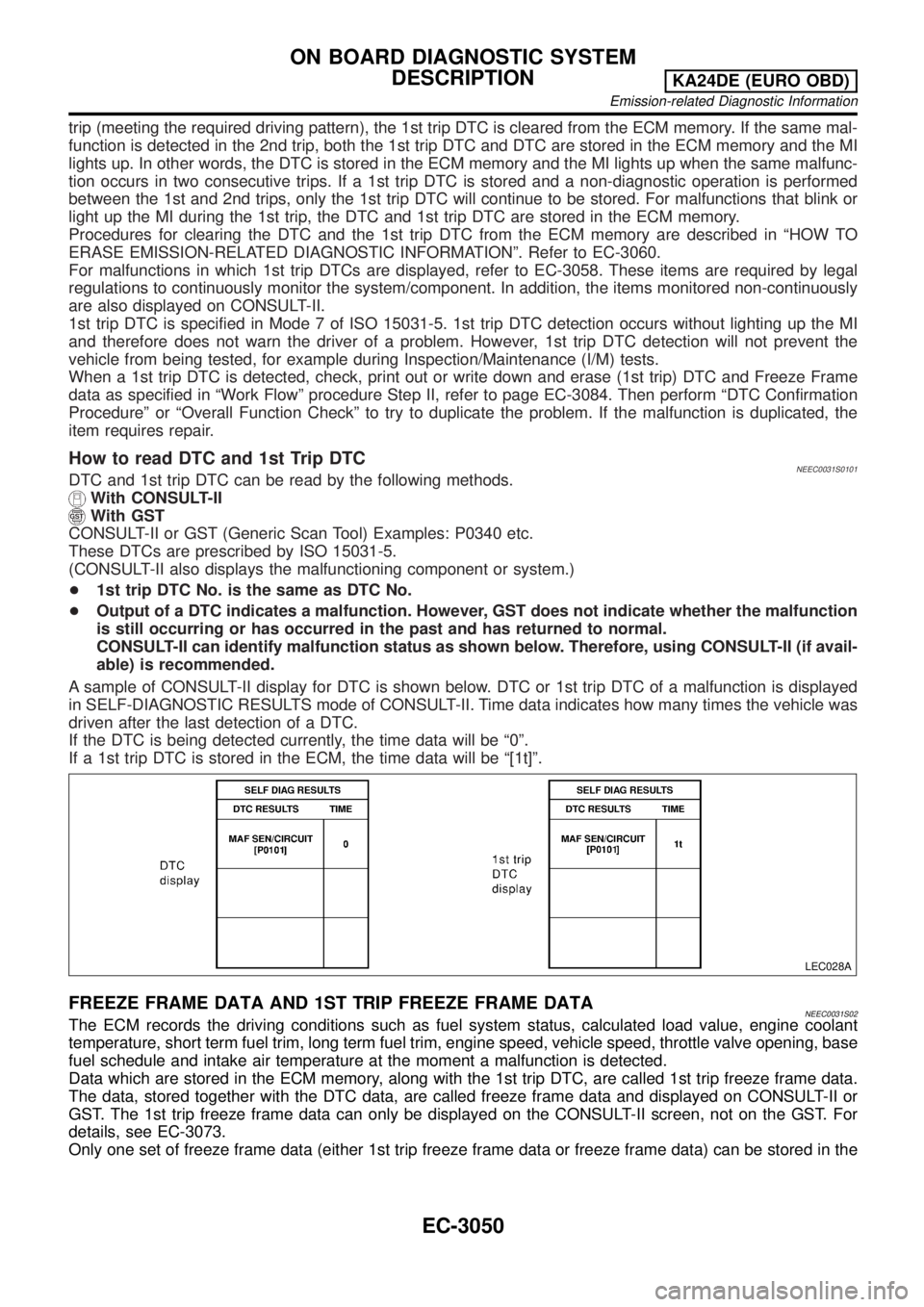
A sample of CONSULT-II display for DTC is shown below. DTC or 1st trip DTC of a malfunction is displayed
in SELF-DIAGNOSTIC RESULTS mode of CONSULT-II. Time data indicates how many times the vehicle was
driven after the last detection of a DTC.
If the DTC is being detected currently, the time data will be ª0º.
If a 1st trip DTC is stored in the ECM, the time data will be ª[1t]º.
LEC028A
FREEZE FRAME DATA AND 1ST TRIP FREEZE FRAME DATANEEC0031S02The ECM records the driving conditions such as fuel system status, calculated load value, engine coolant
temperature, short term fuel trim, long term fuel trim, engine speed, vehicle speed, throttle valve opening, base
fuel schedule and intake air temperature at the moment a malfunction is detected.
Data which are stored in the ECM memory, along with the 1st trip DTC, are called 1st trip freeze frame data.
The data, stored together with the DTC data, are called freeze frame data and displayed on CONSULT-II or
GST. The 1st trip freeze frame data can only be displayed on the CONSULT-II screen, not on the GST. For
details, see EC-3073.
Only one set of freeze frame data (either 1st trip freeze frame data or freeze frame data) can be stored in the
ON BOARD DIAGNOSTIC SYSTEM
DESCRIPTION
KA24DE (EURO OBD)
Emission-related Diagnostic Information
EC-3050
Page 76 of 1306
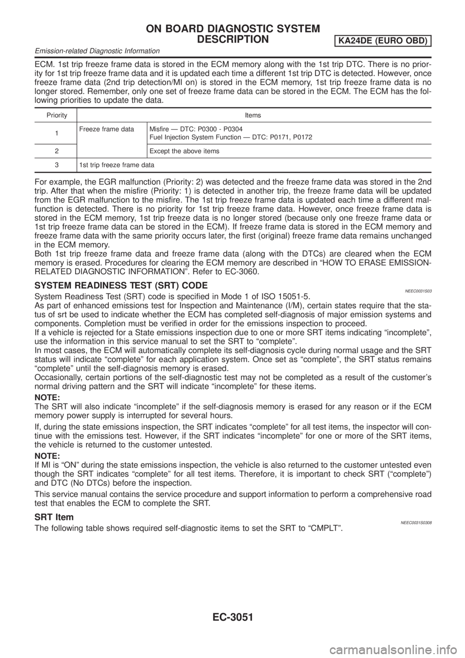
ECM. 1st trip freeze frame data is stored in the ECM memory along with the 1st trip DTC. There is no prior-
ity for 1st trip freeze frame data and it is updated each time a different 1st trip DTC is detected. However, once
freeze frame data (2nd trip detection/MI on) is stored in the ECM memory, 1st trip freeze frame data is no
longer stored. Remember, only one set of freeze frame data can be stored in the ECM. The ECM has the fol-
lowing priorities to update the data.
Priority Items
1Freeze frame data Misfire Ð DTC: P0300 - P0304
Fuel Injection System Function Ð DTC: P0171, P0172
2 Except the above items
3 1st trip freeze frame data
For example, the EGR malfunction (Priority: 2) was detected and the freeze frame data was stored in the 2nd
trip. After that when the misfire (Priority: 1) is detected in another trip, the freeze frame data will be updated
from the EGR malfunction to the misfire. The 1st trip freeze frame data is updated each time a different mal-
function is detected. There is no priority for 1st trip freeze frame data. However, once freeze frame data is
stored in the ECM memory, 1st trip freeze data is no longer stored (because only one freeze frame data or
1st trip freeze frame data can be stored in the ECM). If freeze frame data is stored in the ECM memory and
freeze frame data with the same priority occurs later, the first (original) freeze frame data remains unchanged
in the ECM memory.
Both 1st trip freeze frame data and freeze frame data (along with the DTCs) are cleared when the ECM
memory is erased. Procedures for clearing the ECM memory are described in ªHOW TO ERASE EMISSION-
RELATED DIAGNOSTIC INFORMATIONº. Refer to EC-3060.
SYSTEM READINESS TEST (SRT) CODENEEC0031S03System Readiness Test (SRT) code is specified in Mode 1 of ISO 15051-5.
As part of enhanced emissions test for Inspection and Maintenance (I/M), certain states require that the sta-
tus of srt be used to indicate whether the ECM has completed self-diagnosis of major emission systems and
components. Completion must be verified in order for the emissions inspection to proceed.
If a vehicle is rejected for a State emissions inspection due to one or more SRT items indicating ªincompleteº,
use the information in this service manual to set the SRT to ªcompleteº.
In most cases, the ECM will automatically complete its self-diagnosis cycle during normal usage and the SRT
status will indicate ªcompleteº for each application system. Once set as ªcompleteº, the SRT status remains
ªcompleteº until the self-diagnosis memory is erased.
Occasionally, certain portions of the self-diagnostic test may not be completed as a result of the customer's
normal driving pattern and the SRT will indicate ªincompleteº for these items.
NOTE:
The SRT will also indicate ªincompleteº if the self-diagnosis memory is erased for any reason or if the ECM
memory power supply is interrupted for several hours.
If, during the state emissions inspection, the SRT indicates ªcompleteº for all test items, the inspector will con-
tinue with the emissions test. However, if the SRT indicates ªincompleteº for one or more of the SRT items,
the vehicle is returned to the customer untested.
NOTE:
If MI is ªONº during the state emissions inspection, the vehicle is also returned to the customer untested even
though the SRT indicates ªcompleteº for all test items. Therefore, it is important to check SRT (ªcompleteº)
and DTC (No DTCs) before the inspection.
This service manual contains the service procedure and support information to perform a comprehensive road
test that enables the ECM to complete the SRT.
SRT ItemNEEC0031S0308The following table shows required self-diagnostic items to set the SRT to ªCMPLTº.
ON BOARD DIAGNOSTIC SYSTEM
DESCRIPTION
KA24DE (EURO OBD)
Emission-related Diagnostic Information
EC-3051
Page 97 of 1306
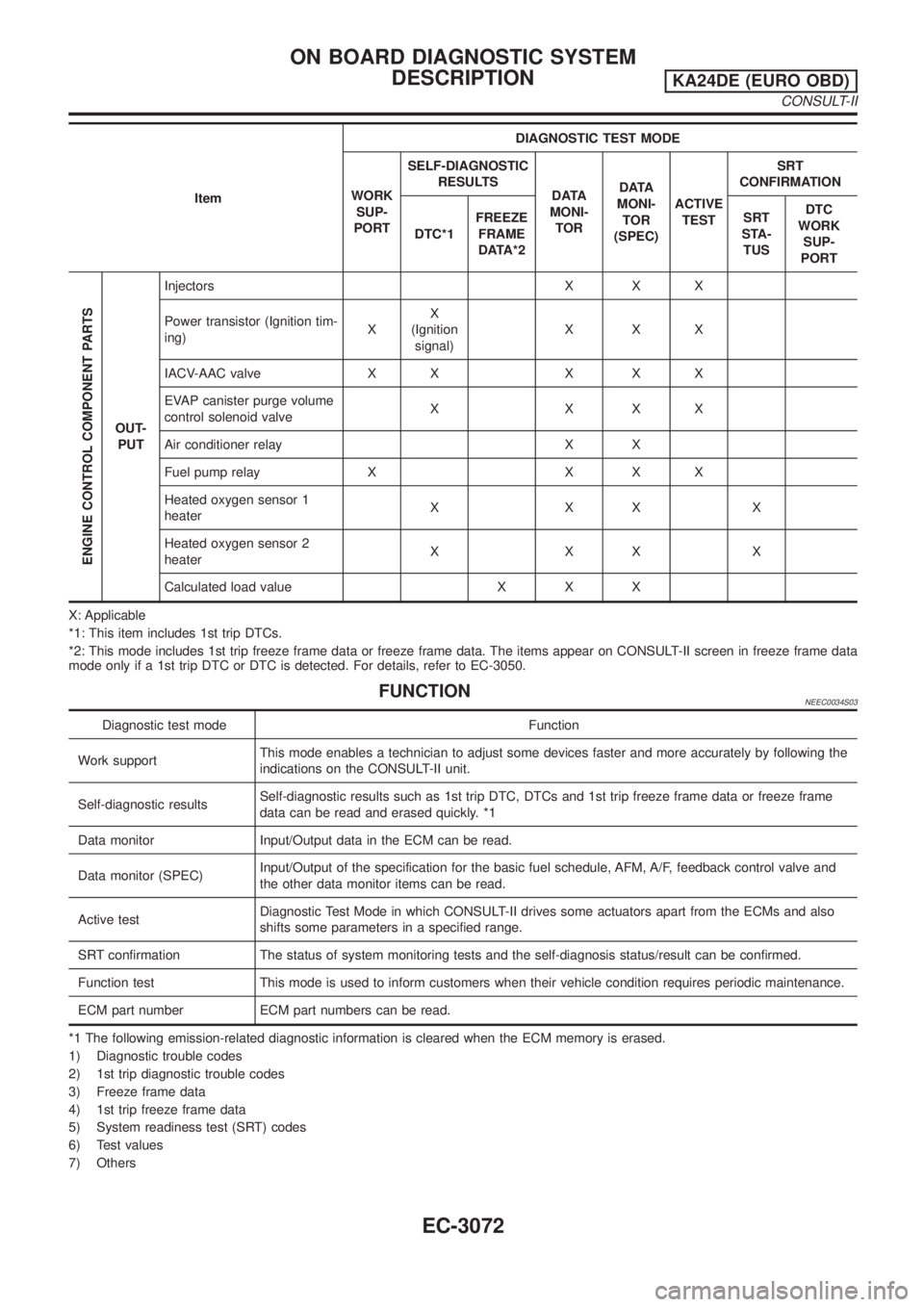
ItemDIAGNOSTIC TEST MODE
WORK
SUP-
PORTSELF-DIAGNOSTIC
RESULTS
DATA
MONI-
TORDATA
MONI-
TOR
(SPEC)ACTIVE
TESTSRT
CONFIRMATION
DTC*1FREEZE
FRAME
DATA*2SRT
STA-
TUSDTC
WORK
SUP-
PORT
ENGINE CONTROL COMPONENT PARTS
OUT-
PUTInjectors X X X
Power transistor (Ignition tim-
ing)XX
(Ignition
signal)XXX
IACV-AAC valve X X X X X
EVAP canister purge volume
control solenoid valveXXXX
Air conditioner relay X X
Fuel pump relay X X X X
Heated oxygen sensor 1
heaterXXXX
Heated oxygen sensor 2
heaterXXXX
Calculated load value X X X
X: Applicable
*1: This item includes 1st trip DTCs.
*2: This mode includes 1st trip freeze frame data or freeze frame data. The items appear on CONSULT-II screen in freeze frame data
mode only if a 1st trip DTC or DTC is detected. For details, refer to EC-3050.
FUNCTIONNEEC0034S03
Diagnostic test mode Function
Work supportThis mode enables a technician to adjust some devices faster and more accurately by following the
indications on the CONSULT-II unit.
Self-diagnostic resultsSelf-diagnostic results such as 1st trip DTC, DTCs and 1st trip freeze frame data or freeze frame
data can be read and erased quickly. *1
Data monitor Input/Output data in the ECM can be read.
Data monitor (SPEC)Input/Output of the specification for the basic fuel schedule, AFM, A/F, feedback control valve and
the other data monitor items can be read.
Active testDiagnostic Test Mode in which CONSULT-II drives some actuators apart from the ECMs and also
shifts some parameters in a specified range.
SRT confirmation The status of system monitoring tests and the self-diagnosis status/result can be confirmed.
Function test This mode is used to inform customers when their vehicle condition requires periodic maintenance.
ECM part number ECM part numbers can be read.
*1 The following emission-related diagnostic information is cleared when the ECM memory is erased.
1) Diagnostic trouble codes
2) 1st trip diagnostic trouble codes
3) Freeze frame data
4) 1st trip freeze frame data
5) System readiness test (SRT) codes
6) Test values
7) Others
ON BOARD DIAGNOSTIC SYSTEM
DESCRIPTION
KA24DE (EURO OBD)
CONSULT-II
EC-3072
Page 111 of 1306

Basic InspectionNEEC0038Precaution:
Perform Basic Inspection without electrical or mechanical
loads applied;
+Headlamp switch is OFF,
+Air conditioner switch is OFF,
+Rear window defogger switch is OFF,
+Steering wheel is in the straight-ahead position, etc.
1 INSPECTION START
1. Check service records for any recent repairs that may indicate a related problem, or the current need for scheduled
maintenance.
2. Open engine hood and check the following:
+Harness connectors for improper connections
+Vacuum hoses for splits, kinks, or improper connections
+Wiring for improper connections, pinches, or cuts
SEF142I
With CONSULT-II©GO TO 2.
With GST©GO TO 4.
No tools©GO TO 5.
2 CONNECT CONSULT-II TO THE VEHICLE
Connect ªCONSULT-IIº to the data link connector and select ªENGINEº from the menu. Refer to EC-3070.
SEC305D
©GO TO 3.
TROUBLE DIAGNOSIS Ð BASIC
INSPECTION
KA24DE (EURO OBD)
Basic Inspection
EC-3086