Page 280 of 1306
7 CHECK SPARK PLUGS
Remove the spark plugs and check for fouling, etc.
SEF156I
OK or NG
OK©GO TO 8.
NG©Repair or replace spark plug(s) with standard type one(s). For spark plug type, refer to
ªENGINE MAINTENANCEº, MA section.
8 CHECK COMPRESSION PRESSURE
Refer to EM section.
+Check compression pressure.
Standard:
1,226 kPa (12.3 bar, 12.5 kg/cm
2, 178 psi)/300 rpm
Minimum:
1,030 kPa (10.3 bar, 10.5 kg/cm
2, 149 psi)/300 rpm
Difference between each cylinder:
98 kPa (0.98 bar, 1.0 kg/cm
2, 14 psi)/300 rpm
OK or NG
OK©GO TO 9.
NG©Check pistons, piston rings, valves, valve seats and cylinder head gaskets.
9 CHECK FUEL PRESSURE
1. Install any parts removed.
2. Release fuel pressure to zero. Refer to EC-3033.
3. Install fuel pressure gauge and check fuel pressure.
AEC064B
At idle: Approx. 235 kPa (2.35 bar, 2.4 kg/cm2, 34 psi)
OK or NG
OK©GO TO 11.
NG©GO TO 10.
DTC P0300 - P0304 NO.4-1CYLINDER MISFIRE, MULTIPLE CYLINDER
MISFIRE
KA24DE (EURO OBD)
Diagnostic Procedure
EC-3255
Page 373 of 1306

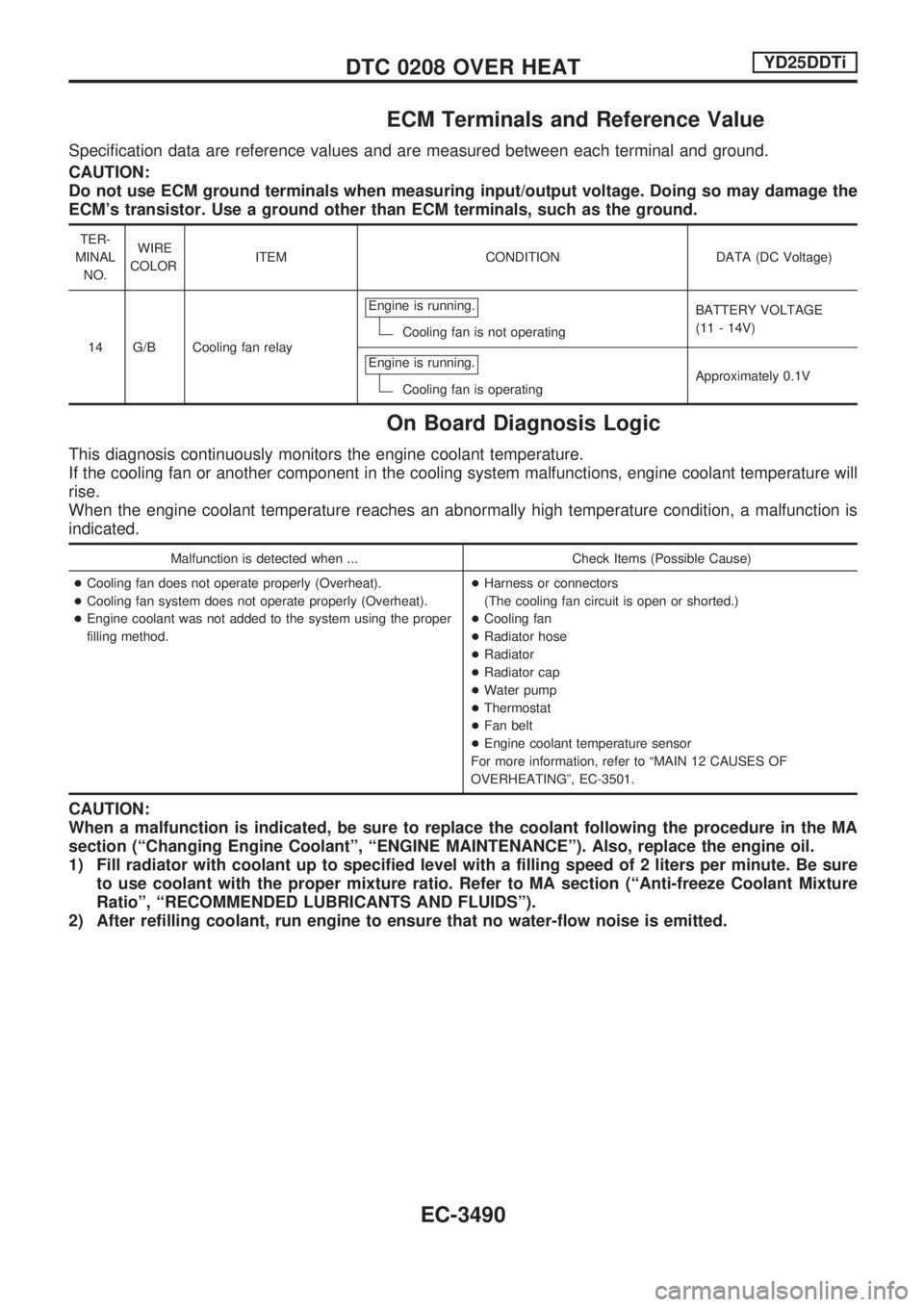
Main 11 Causes of OverheatingNEEC1537
Engine Step Inspection item Equipment Standard Reference page
OFF 1+Blocked radiator
+Blocked condenser
+Blocked radiator grille
+Blocked bumper+Visual No blocking Ð
2+Coolant mixture+Coolant tester 50 - 50% coolant mix-
tureSee MA section, ªRECOM-
MENDED FLUIDS AND
LUBRICANTSº.
3+Coolant level+Visual Coolant up to MAX level
in reservoir tank and
radiator filler neckSee MA section, ªChang-
ing Engine Coolantº.
4+Radiator cap+Pressure tester 78 - 98 kPa
(0.78 - 0.98 bar,
0.8 - 1.0 kg/cm
2,
11 - 14 psi)
59-98kPa
(0.59 - 0.98 bar,
0.6 - 1.0 kg/cm
2,
9 - 14 psi) (Limit)See LC section, ªSystem
Checkº.
ON*
25+Coolant leaks+Visual No leaks See LC section, ªSystem
Checkº.
ON*
26+Thermostat+Touch the upper and
lower radiator hosesBoth hoses should be
hotSee LC section, ªThermo-
statº and LC section,
ªRadiatorº.
OFF 7+Combustion gas leak+Color checker chemical
tester 4 Gas analyzerNegative Ð
ON*
38+Coolant temperature
gauge+Visual Gauge less than 3/4
when drivingÐ
+Coolant overflow to
reservoir tank+Visual No overflow during driv-
ing and idlingSee MA section, ªChang-
ing Engine Coolantº.
OFF*
49+Coolant return from
reservoir tank to
radiator+Visual Should be initial level in
reservoir tankSee MA section, ªENGINE
MAINTENANCEº.
OFF 10+Cylinder head+Straight gauge feeler
gauge0.1 mm (0.004 in) Maxi-
mum distortion (warping)See EM section, ªInspec-
tionº.
11+Cylinder block and
pistons+Visual No scuffing on cylinder
walls or pistonSee EM section, ªInspec-
tion².
*1: Turn the ignition switch ON.
*2: Engine running at 3,000 rpm for 10 minutes.
*3: Drive at 90 km/h (55 MPH) for 30 minutes and then let idle for 10 minutes.
*4: After 60 minutes of cool down time.
For more information, refer to LC section, ªOVERHEATING CAUSE ANALYSISº.
DTC P1217 ENGINE OVER
TEMPERATURE
KA24DE (EURO OBD)
Main 11 Causes of Overheating
EC-3348
Page 464 of 1306
FUNCTION TEST
This mode is used to inform customers of their vehicle condition of periodic maintenance.
SEF720X
ON BOARD DIAGNOSTIC SYSTEM DESCRIPTIONYD25DDTi
CONSULT-II (Cont'd)
EC-3439
Page 467 of 1306
Work Flow
*1 Refer to MA section (ªChecking and
Replacing Fuel Filter and Draining
Waterº, ªENGINE MAINTENANCEº).
*2 If time data of ªSELF-DIAG
RESULTSº is other than ª0º, per-
form ªTROUBLE DIAGNOSIS FOR
INTERMITTENT INCIDENTº,
EC-3470.*3 If the incident cannot be verified,
perform ªTROUBLE DIAGNOSIS
FOR INTERMITTENT INCIDENTº,
EC-3470.
*4 If the on board diagnostic system
cannot be performed, check main
power supply and ground circuit.
Refer to ªTROUBLE DIAGNOSISFOR POWER SUPPLYº, EC-3471.
*5 If malfunctioning part cannot be
detected, perform ªTROUBLE
DIAGNOSIS FOR INTERMITTENT
INCIDENTº, EC-3470.SEF374YC
TROUBLE DIAGNOSIS Ð INTRODUCTIONYD25DDTi
EC-3442
Page 469 of 1306

Basic Inspection
Precaution:
Perform Basic Inspection without electrical or mechanical
loads applied;
+Shift lever is in neutral position,
+Heat up switch is OFF,
+Headlamp switch is OFF,
+Air conditioner switch is OFF,
+Rear defogger switch is OFF,
+Steering wheel is in the straight-ahead position, etc.
1 INSPECTION START
1. Check service records for any recent repairs that may indicate a related problem.
2. Check the current need for scheduled maintenance, especially for fuel filter and air cleaner filter. Refer to MA section.
3. Open engine hood and check the following:
+Harness connectors for improper connections
+Vacuum hoses for splits, kinks, or improper connections
+Wiring for improper connections, pinches, or cuts
SEF142I
4. Start engine and warm it up to the normal operating temperature.
cGO TO 2.
2 PREPARATION FOR CHECKING IDLE SPEED
With CONSULT-II
Connect CONSULT-II to the data link connector.
Without CONSULT-II
Install diesel tacho tester to the vehicle.
cGO TO 3.
TROUBLE DIAGNOSIS Ð BASIC INSPECTIONYD25DDTi
EC-3444
Page 515 of 1306

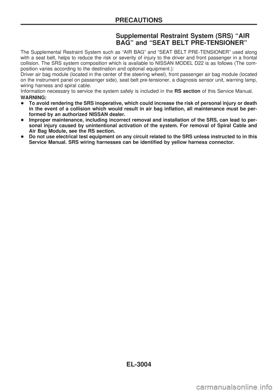
ECM Terminals and Reference Value
Specification data are reference values and are measured between each terminal and ground.
CAUTION:
Do not use ECM ground terminals when measuring input/output voltage. Doing so may damage the
ECM's transistor. Use a ground other than ECM terminals, such as the ground.
TER-
MINAL
NO.WIRE
COLORITEM CONDITION DATA (DC Voltage)
14 G/B Cooling fan relayEngine is running.
Cooling fan is not operatingBATTERY VOLTAGE
(11 - 14V)
Engine is running.
Cooling fan is operatingApproximately 0.1V
On Board Diagnosis Logic
This diagnosis continuously monitors the engine coolant temperature.
If the cooling fan or another component in the cooling system malfunctions, engine coolant temperature will
rise.
When the engine coolant temperature reaches an abnormally high temperature condition, a malfunction is
indicated.
Malfunction is detected when ... Check Items (Possible Cause)
+Cooling fan does not operate properly (Overheat).
+Cooling fan system does not operate properly (Overheat).
+Engine coolant was not added to the system using the proper
filling method.+Harness or connectors
(The cooling fan circuit is open or shorted.)
+Cooling fan
+Radiator hose
+Radiator
+Radiator cap
+Water pump
+Thermostat
+Fan belt
+Engine coolant temperature sensor
For more information, refer to ªMAIN 12 CAUSES OF
OVERHEATINGº, EC-3501.
CAUTION:
When a malfunction is indicated, be sure to replace the coolant following the procedure in the MA
section (ªChanging Engine Coolantº, ªENGINE MAINTENANCEº). Also, replace the engine oil.
1) Fill radiator with coolant up to specified level with a filling speed of 2 liters per minute. Be sure
to use coolant with the proper mixture ratio. Refer to MA section (ªAnti-freeze Coolant Mixture
Ratioº, ªRECOMMENDED LUBRICANTS AND FLUIDSº).
2) After refilling coolant, run engine to ensure that no water-flow noise is emitted.
DTC 0208 OVER HEATYD25DDTi
EC-3490
Page 679 of 1306

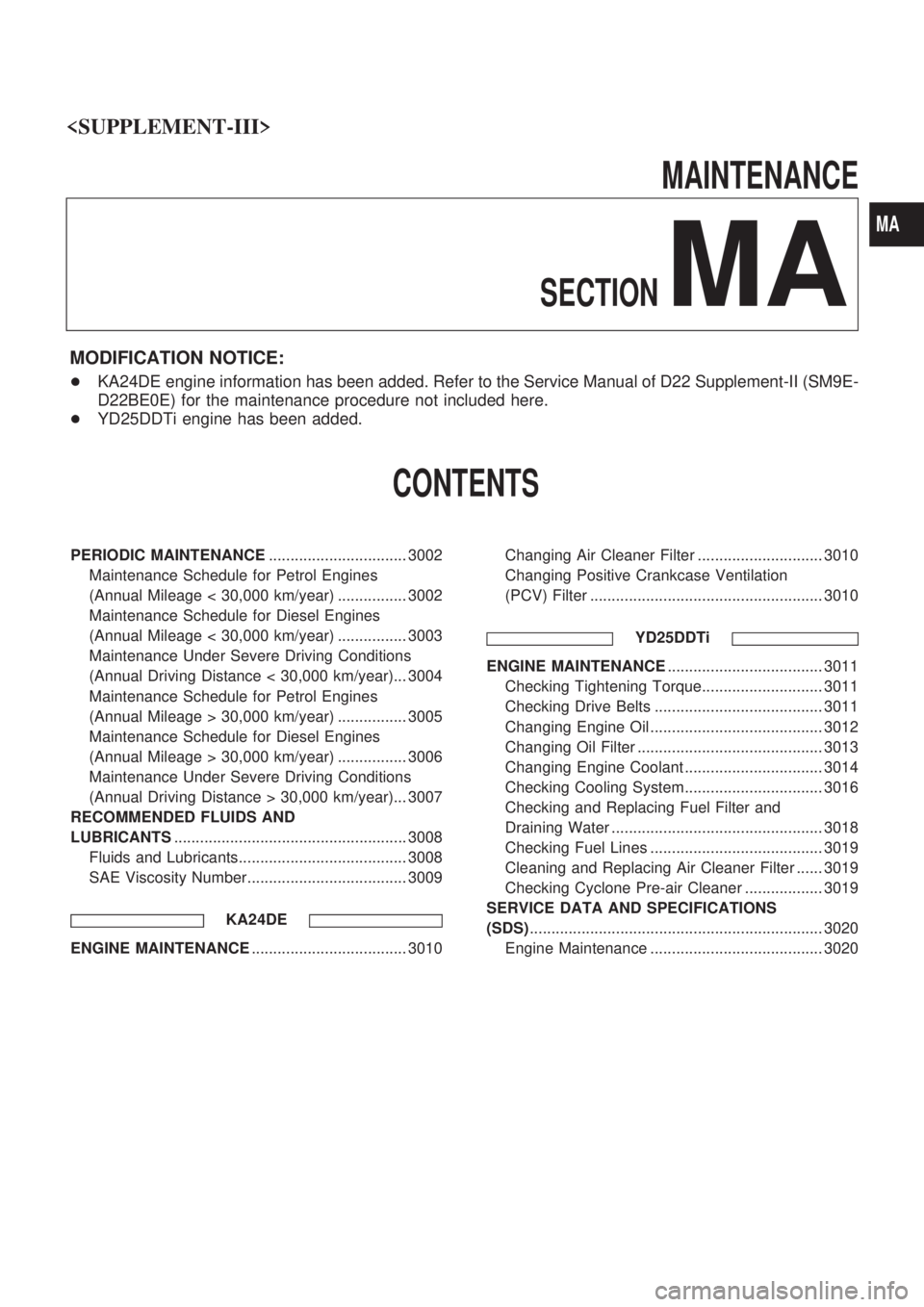
Supplemental Restraint System (SRS) ªAIR
BAGº and ªSEAT BELT PRE-TENSIONERº
The Supplemental Restraint System such as ªAIR BAGº and ªSEAT BELT PRE-TENSIONERº used along
with a seat belt, helps to reduce the risk or severity of injury to the driver and front passenger in a frontal
collision. The SRS system composition which is available to NISSAN MODEL D22 is as follows (The com-
position varies according to the destination and optional equipment.):
Driver air bag module (located in the center of the steering wheel), front passenger air bag module (located
on the instrument panel on passenger side), seat belt pre-tensioner, a diagnosis sensor unit, warning lamp,
wiring harness and spiral cable.
Information necessary to service the system safely is included in theRS sectionof this Service Manual.
WARNING:
+To avoid rendering the SRS inoperative, which could increase the risk of personal injury or death
in the event of a collision which would result in air bag inflation, all maintenance must be per-
formed by an authorized NISSAN dealer.
+Improper maintenance, including incorrect removal and installation of the SRS, can lead to per-
sonal injury caused by unintentional activation of the system. For removal of Spiral Cable and
Air Bag Module, see the RS section.
+Do not use electrical test equipment on any circuit related to the SRS unless instructed to in this
Service Manual. SRS wiring harnesses can be identified by yellow harness connector.
PRECAUTIONS
EL-3004
Page 1023 of 1306

MAINTENANCE
SECTION
MA
MODIFICATION NOTICE:
+KA24DE engine information has been added. Refer to the Service Manual of D22 Supplement-II (SM9E-
D22BE0E) for the maintenance procedure not included here.
+YD25DDTi engine has been added.
CONTENTS
PERIODIC MAINTENANCE................................ 3002
Maintenance Schedule for Petrol Engines
(Annual Mileage < 30,000 km/year) ................ 3002
Maintenance Schedule for Diesel Engines
(Annual Mileage < 30,000 km/year) ................ 3003
Maintenance Under Severe Driving Conditions
(Annual Driving Distance < 30,000 km/year)... 3004
Maintenance Schedule for Petrol Engines
(Annual Mileage > 30,000 km/year) ................ 3005
Maintenance Schedule for Diesel Engines
(Annual Mileage > 30,000 km/year) ................ 3006
Maintenance Under Severe Driving Conditions
(Annual Driving Distance > 30,000 km/year)... 3007
RECOMMENDED FLUIDS AND
LUBRICANTS...................................................... 3008
Fluids and Lubricants....................................... 3008
SAE Viscosity Number..................................... 3009
KA24DE
ENGINE MAINTENANCE.................................... 3010Changing Air Cleaner Filter ............................. 3010
Changing Positive Crankcase Ventilation
(PCV) Filter ...................................................... 3010
YD25DDTi
ENGINE MAINTENANCE.................................... 3011
Checking Tightening Torque............................ 3011
Checking Drive Belts ....................................... 3011
Changing Engine Oil ........................................ 3012
Changing Oil Filter ........................................... 3013
Changing Engine Coolant ................................ 3014
Checking Cooling System................................ 3016
Checking and Replacing Fuel Filter and
Draining Water ................................................. 3018
Checking Fuel Lines ........................................ 3019
Cleaning and Replacing Air Cleaner Filter ...... 3019
Checking Cyclone Pre-air Cleaner .................. 3019
SERVICE DATA AND SPECIFICATIONS
(SDS).................................................................... 3020
Engine Maintenance ........................................ 3020
MA