2001 NISSAN PICK-UP wheel bolts
[x] Cancel search: wheel boltsPage 896 of 1306
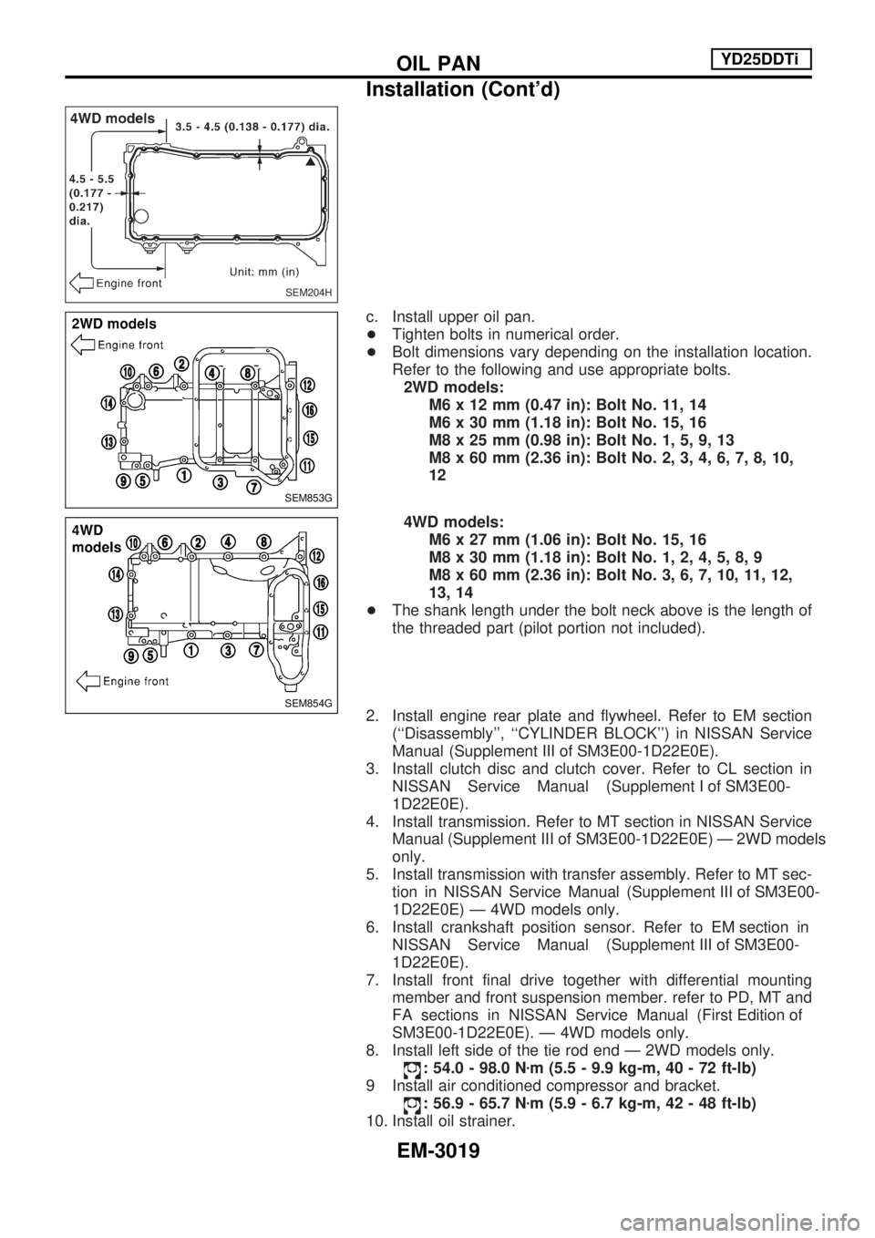
c. Install upper oil pan.
+Tighten bolts in numerical order.
+ Bolt dimensions vary depending on the installation location.
Refer to the following and use appropriate bolts.
2WD models: M6 x 12 mm (0.47 in): Bolt No. 11, 14
M6 x 30 mm (1.18 in): Bolt No. 15, 16
M8 x 25 mm (0.98 in): Bolt No. 1, 5, 9, 13
M8 x 60 mm (2.36 in): Bolt No. 2, 3, 4, 6, 7, 8, 10,
12
4WD models: M6 x 27 mm (1.06 in): Bolt No. 15, 16
M8 x 30 mm (1.18 in): Bolt No. 1, 2, 4, 5, 8, 9
M8 x 60 mm (2.36 in): Bolt No. 3, 6, 7, 10, 11, 12,
13, 14
+ The shank length under the bolt neck above is the length of
the threaded part (pilot portion not included).
2. Install engine rear plate and flywheel. Refer to EM section (``Disassembly'', ``CYLINDER BLOCK'') in NISSAN Service
Manual(Supplement III of SM3E00-1D22E0E).
3. Install clutch disc and clutch cover. Refer to CL section in NISSANServiceManual(Supplement I of SM3E00-
1D22E0E).
4. Install transmission. Refer to MT section in NISSAN Service Manual(Supplement III of SM3E00-1D22E0E)Ð2WDmodels
only.
5. Install transmission with transfer assembly. Refer to MT sec- tioninNISSANServiceManual(Supplement III of SM3E00-
1D22E0E) Ð 4WD models only.
6.Installcrankshaftpositionsensor.RefertoEM sectionin NISSANServiceManual(Supplement III of SM3E00-
1D22E0E).
7. Install front final drive together with differential mounting member and front suspension member. refer to PD, MT and
FAsectionsinNISSANServiceManual(First Edition of
SM3E00-1D22E0E). Ð 4WD models only.
8. Install left side of the tie rod end Ð 2WD models only.
: 54.0 - 98.0 N zm (5.5 - 9.9 kg-m, 40 - 72 ft-lb)
9 Install air conditioned compressor and bracket.
: 56.9 - 65.7 N zm (5.9 - 6.7 kg-m, 42 - 48 ft-lb)
10. Install oil strainer.
SEM204H
SEM853G
SEM854G
OILPAN YD25DDTi
Installation (Cont'd)
EM-3019
Page 940 of 1306
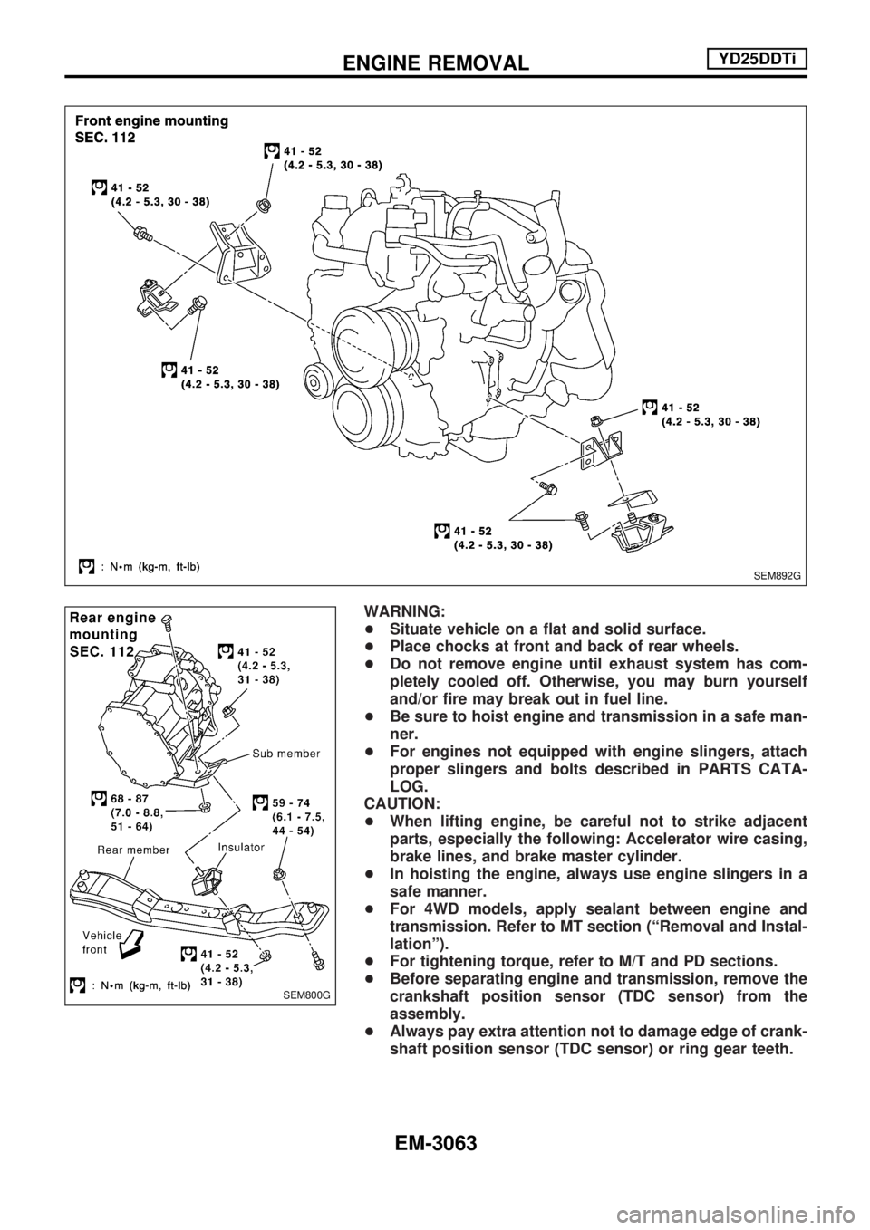
WARNING:
+Situate vehicle on a flat and solid surface.
+Place chocks at front and back of rear wheels.
+Do not remove engine until exhaust system has com-
pletely cooled off. Otherwise, you may burn yourself
and/or fire may break out in fuel line.
+Be sure to hoist engine and transmission in a safe man-
ner.
+For engines not equipped with engine slingers, attach
proper slingers and bolts described in PARTS CATA-
LOG.
CAUTION:
+When lifting engine, be careful not to strike adjacent
parts, especially the following: Accelerator wire casing,
brake lines, and brake master cylinder.
+In hoisting the engine, always use engine slingers in a
safe manner.
+For 4WD models, apply sealant between engine and
transmission. Refer to MT section (ªRemoval and Instal-
lationº).
+For tightening torque, refer to M/T and PD sections.
+Before separating engine and transmission, remove the
crankshaft position sensor (TDC sensor) from the
assembly.
+Always pay extra attention not to damage edge of crank-
shaft position sensor (TDC sensor) or ring gear teeth.
SEM892G
SEM800G
ENGINE REMOVALYD25DDTi
EM-3063
Page 944 of 1306
Removal and Installation
CAUTION:
+When installing bearings, pistons, or other sliding parts,
lubricate contacting surfaces with new engine oil.
+Place removed parts such as bearings and bearing caps
in their proper order and direction.
+When installing connecting rod nuts, and main bearing
cap bolts, apply new engine oil to threads and seating
surfaces.
+Do not allow any magnetic materials to contact the sig-
nal plate of flywheel.
+Do not remove the signal plate at back.
+Do not place the signal plate side facing under.
+Handle with care so as not to damage the signal plate
[especially four places on protrusions for signal of crank
position sensor (TDC sensor)].
Disassembly
PISTON AND CRANKSHAFT
1. Remove engine. Refer to ªENGINE REMOVALº, EM-3063.
2. Place engine on a work stand.
a. Remove flywheel.
+Hold ring gear with ring gear stopper (KV10105630,
KV10105610). Then, loosen securing bolts with TORX
socket (size: Q8 E20, Commercial Service Tool) and remove
them. As an alternative method, hold the crankshaft pulley
with a pulley holder (SST) to remove the flywheel.
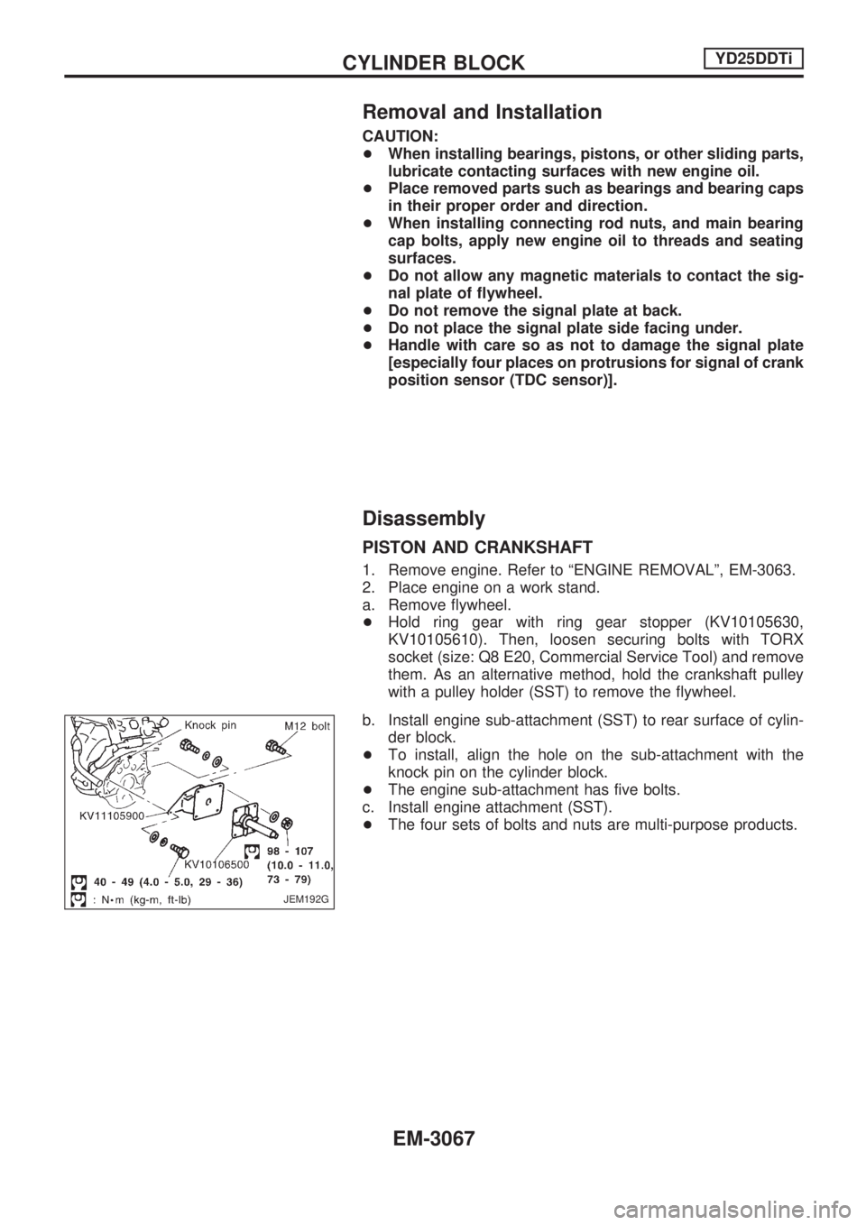
b. Install engine sub-attachment (SST) to rear surface of cylin-
der block.
+To install, align the hole on the sub-attachment with the
knock pin on the cylinder block.
+The engine sub-attachment has five bolts.
c. Install engine attachment (SST).
+The four sets of bolts and nuts are multi-purpose products.
JEM192G
CYLINDER BLOCKYD25DDTi
EM-3067
Page 957 of 1306
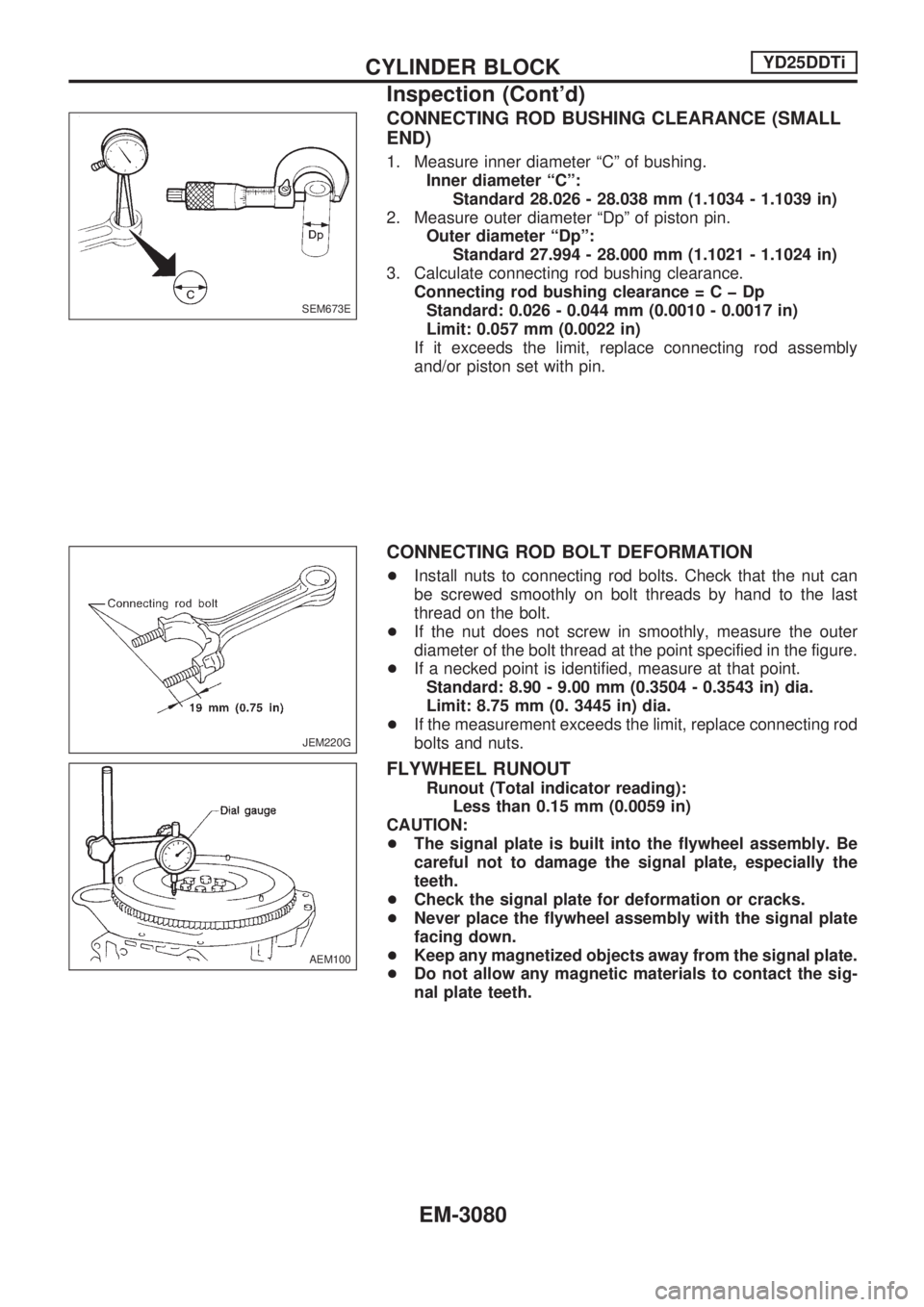
CONNECTING ROD BUSHING CLEARANCE (SMALL
END)
1. Measure inner diameter ªCº of bushing.
Inner diameter ªCº:
Standard 28.026 - 28.038 mm (1.1034 - 1.1039 in)
2. Measure outer diameter ªDpº of piston pin.
Outer diameter ªDpº:
Standard 27.994 - 28.000 mm (1.1021 - 1.1024 in)
3. Calculate connecting rod bushing clearance.
Connecting rod bushing clearance=CþDp
Standard: 0.026 - 0.044 mm (0.0010 - 0.0017 in)
Limit: 0.057 mm (0.0022 in)
If it exceeds the limit, replace connecting rod assembly
and/or piston set with pin.
CONNECTING ROD BOLT DEFORMATION
+Install nuts to connecting rod bolts. Check that the nut can
be screwed smoothly on bolt threads by hand to the last
thread on the bolt.
+If the nut does not screw in smoothly, measure the outer
diameter of the bolt thread at the point specified in the figure.
+If a necked point is identified, measure at that point.
Standard: 8.90 - 9.00 mm (0.3504 - 0.3543 in) dia.
Limit: 8.75 mm (0. 3445 in) dia.
+If the measurement exceeds the limit, replace connecting rod
bolts and nuts.
FLYWHEEL RUNOUT
Runout (Total indicator reading):
Less than 0.15 mm (0.0059 in)
CAUTION:
+The signal plate is built into the flywheel assembly. Be
careful not to damage the signal plate, especially the
teeth.
+Check the signal plate for deformation or cracks.
+Never place the flywheel assembly with the signal plate
facing down.
+Keep any magnetized objects away from the signal plate.
+Do not allow any magnetic materials to contact the sig-
nal plate teeth.
SEM673E
JEM220G
AEM100
CYLINDER BLOCKYD25DDTi
Inspection (Cont'd)
EM-3080
Page 962 of 1306
20. Remove engine from engine stand in the reverse order of
assembly.
21. Install flywheel.
+Holding ring gear with ring stopper (SST), tighten securing
bolts with TORX-socket (size: Q8 E20, Commercial Service
Tool).
+Tighten bolts uniformly in a crisscross manner.
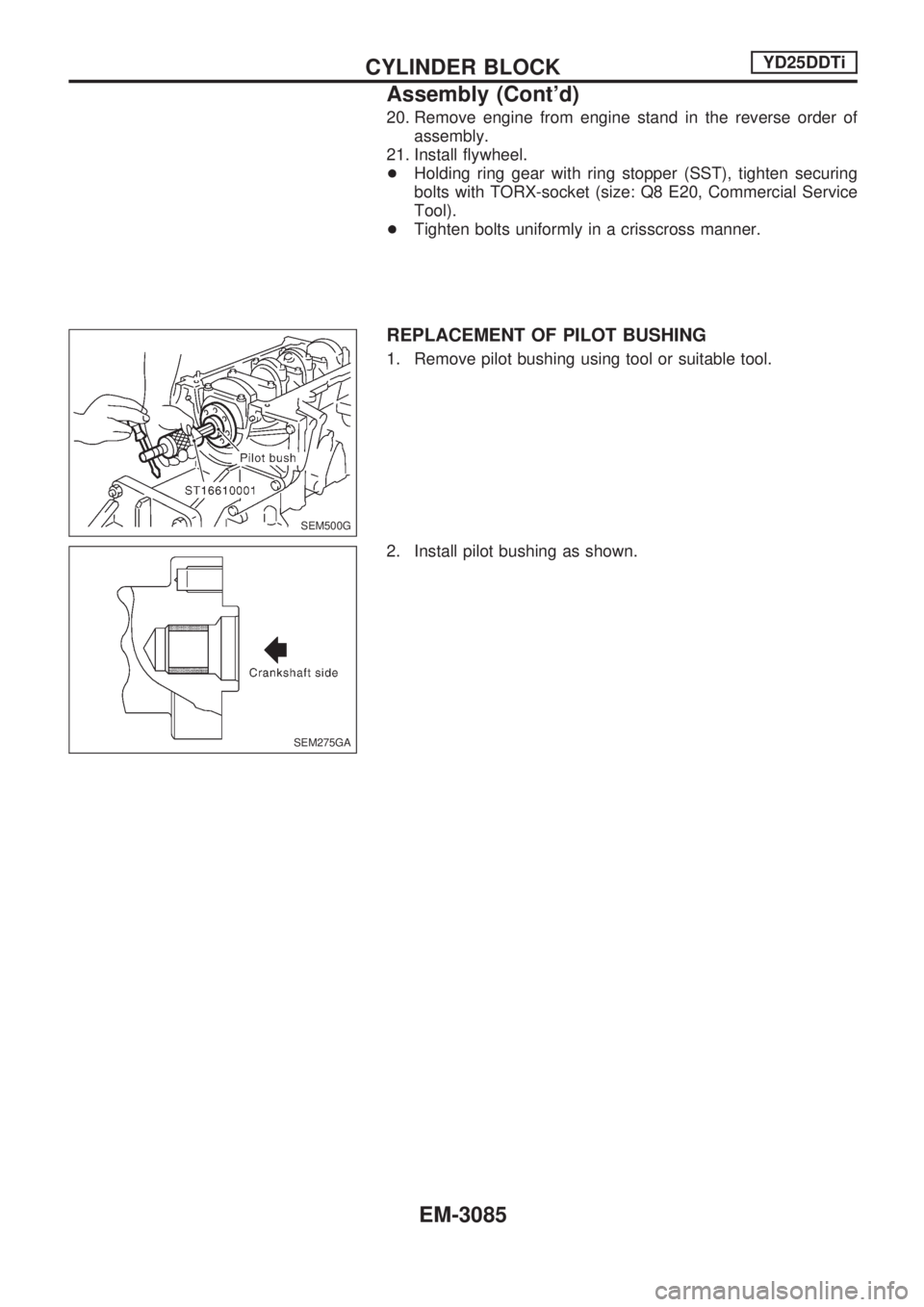
REPLACEMENT OF PILOT BUSHING
1. Remove pilot bushing using tool or suitable tool.
2. Install pilot bushing as shown.
SEM500G
SEM275GA
CYLINDER BLOCKYD25DDTi
Assembly (Cont'd)
EM-3085
Page 1078 of 1306
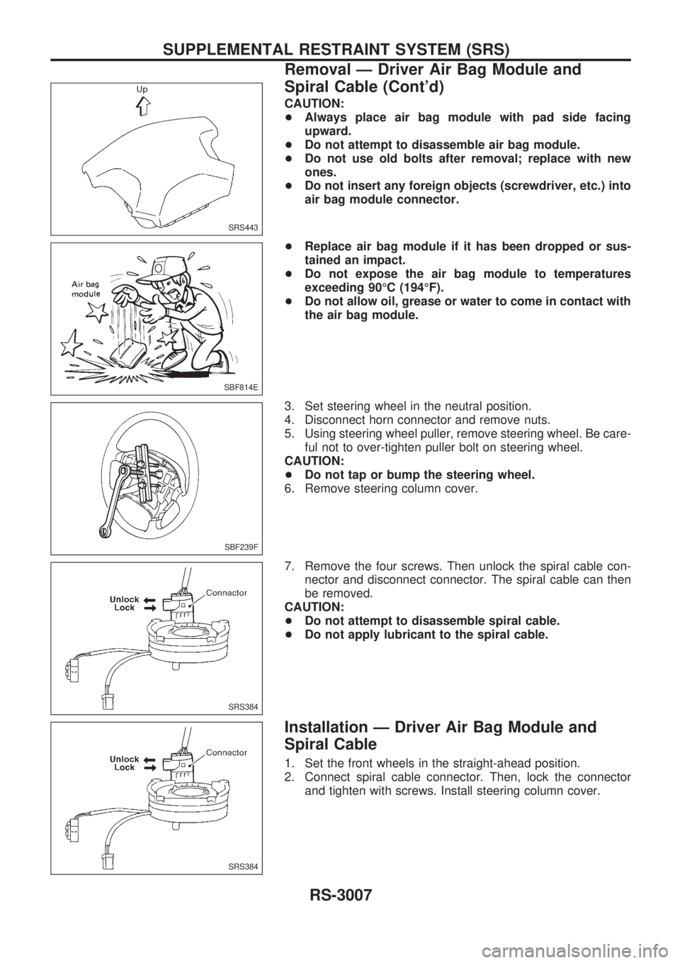
CAUTION:
+Always place air bag module with pad side facing
upward.
+Do not attempt to disassemble air bag module.
+Do not use old bolts after removal; replace with new
ones.
+Do not insert any foreign objects (screwdriver, etc.) into
air bag module connector.
+Replace air bag module if it has been dropped or sus-
tained an impact.
+Do not expose the air bag module to temperatures
exceeding 90ÉC (194ÉF).
+Do not allow oil, grease or water to come in contact with
the air bag module.
3. Set steering wheel in the neutral position.
4. Disconnect horn connector and remove nuts.
5. Using steering wheel puller, remove steering wheel. Be care-
ful not to over-tighten puller bolt on steering wheel.
CAUTION:
+Do not tap or bump the steering wheel.
6. Remove steering column cover.
7. Remove the four screws. Then unlock the spiral cable con-
nector and disconnect connector. The spiral cable can then
be removed.
CAUTION:
+Do not attempt to disassemble spiral cable.
+Do not apply lubricant to the spiral cable.
Installation Ð Driver Air Bag Module and
Spiral Cable
1. Set the front wheels in the straight-ahead position.
2. Connect spiral cable connector. Then, lock the connector
and tighten with screws. Install steering column cover.
SRS443
SBF814E
SBF239F
SRS384
SRS384
SUPPLEMENTAL RESTRAINT SYSTEM (SRS)
Removal Ð Driver Air Bag Module and
Spiral Cable (Cont'd)
RS-3007
Page 1079 of 1306
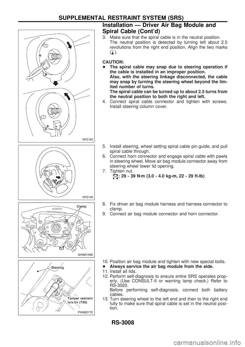
3. Make sure that the spiral cable is in the neutral position.
The neutral position is detected by turning left about 2.5
revolutions from the right end position. Align the two marks
(
,
m).
CAUTION:
+The spiral cable may snap due to steering operation if
the cable is installed in an improper position.
Also, with the steering linkage disconnected, the cable
may snap by turning the steering wheel beyond the lim-
ited number of turns.
The spiral cable can be turned up to about 2.5 turns from
the neutral position to both the right and left.
4. Connect spiral cable connector and tighten with screws.
Install steering column cover.
5. Install steering, wheel setting spiral cable pin guide, and pull
spiral cable through.
6. Connect horn connector and engage spiral cable with pawls
in steering wheel. Move air bag module connector away from
steering wheel lower lid opening.
7. Tighten nut.
:29-39Nzm (3.0 - 4.0 kg-m, 22 - 29 ft-lb)
8. Fix driver air bag module harness and harness connector to
clamp.
9. Connect air bag module connector and horn connector.
10. Position air bag module and tighten with new special bolts.
+Always service the air bag module from the side.
11. Install all lids.
12. Perform self-diagnosis to ensure entire SRS operates prop-
erly. (Use CONSULT-II or warning lamp check.) Refer to
RS-3020.
Before performing self-diagnosis, connect both battery
cables.
13. Turn steering wheel to the left end and then to the right end
fully to make sure that spiral cable is set in the neutral posi-
tion.
SRS165
SRS166
SHIA0144E
PHIA0017E
SUPPLEMENTAL RESTRAINT SYSTEM (SRS)
Installation Ð Driver Air Bag Module and
Spiral Cable (Cont'd)
RS-3008
Page 1108 of 1306
FOR FRONTAL COLLISION
To repair the SRS for a frontal collision, perform the following steps.
When SRS (except the side air bag) is activated in a collision:
V1Replace the diagnosis sensor unit.
V2Remove the air bag modules (except the side air bag module).
V3Check the SRS components using the table shown below:
+Replace any SRS components showing visible signs of damage (dents, cracks, deformation).
V4Install new air bag modules (except the side air bag module).
V5Conduct self-diagnosis using CONSULT-II, and ªAIR BAGº. Refer to ªSelf-diagnosisº for details (RS-
3020). Ensure entire SRS operates properly.
When SRS is not activated in a collision:
V1Check the SRS components using the table shown below:
+Replace any SRS components showing visible signs of damage (dents, cracks, deformation).
V2Conduct self-diagnosis using CONSULT-II, and ªAIR BAGº. Refer to ªSelf-diagnosisº for details (RS-
3020). Ensure entire SRS operates properly.
SRS inspection
Part SRS (except the
side air bag) is acti-
vatedSRS is NOT activated
Air bag module
(driver and passen-
ger side)REPLACE
Install air bag mod-
ule with new bolts.1. Remove air bag module. Check harness cover and connectors for damage, ter-
minals for deformities, and harness for binding.
2-1. Install driver air bag module into the steering wheel to check fit and alignment
with the wheel.
2-2. Install passenger air bag module into the instrument panel to check fit with the
instrument panel.
3. No damage found, reinstall with new bolts.
4. If damagedÐREPLACE. Air bag must be deployed before discarding.
Seat belt pre-ten-
sioner assemblyREPLACE
Install seat belt pre-
tensioner with new
bolts.1. Remove seat belt pre-tensioners.
Check harness cover and connectors for damage, terminals for deformities, and
harness for binding.
2. Check belts for damage and anchors for loose mounting.
3. Check retractor for smooth operation.
4. If no damage is found, reinstall with new bolts coated with bonding agent.
5. If damagedÐREPLACE. Install the seat belt pre-tensioners with new bolts coated
with bonding agent. Seat belt pre-tensioners must be deployed before discarding.
Diagnosis sensor
unitREPLACE
Install diagnosis sen-
sor unit with new
bolts.1. Check case and bracket for dents, cracks or deformities.
2. Check connectors for damage, and terminals for deformities.
3. If no damage is found, reinstall with new bolts.
4. If damagedÐREPLACE. Install diagnosis sensor unit with new bolts.
Steering wheel 1. Visually check steering wheel for deformities.
2. Check harness (built into steering wheel) and connectors for damage, and terminals for deformities.
3. Install air bag module to check fit or alignment with steering wheel.
4. Check steering wheel for excessive free play.
5. If no damage is found, reinstall the steering wheel.
6. If damagedÐREPLACE.
Spiral cable 1. Visually check spiral cable and combination switch for damage.
2. Check connectors, flat cable and protective tape for damage.
3. Check steering wheel for noise, binding or heavy operation.
4. If no damage is found, reinstall the spiral cable.
5. If damagedÐREPLACE.
Harness and Con-
nectors1. Check connectors for poor connection, damage, and terminals for deformities.
2. Check harness for binding, chafing, cuts, or deformities.
3. If no damage is found, reinstall harness and connectors.
4. DamagedÐREPLACE damaged section of harness. Do not attempt to repair, splice or modify any SRS
harness.
Instrument panel 1. Check instrument panel for bending, deformities, or cracks.
2. Check passenger side module brackets for dents, cracks or deformities.
3. If no damage is found, reinstall with new bolts.
4. If damagedÐREPLACE.
COLLISION DIAGNOSIS
RS-3037