2001 NISSAN PICK-UP air condition
[x] Cancel search: air conditionPage 1 of 1306

GENERAL INFORMATIONGI
MAINTENANCEMA
ENGINE MECHANICALEM
ENGINE LUBRICATION &
COOLING SYSTEMSLC
ENGINE CONTROL SYSTEMEC
ACCELERATOR CONTROL, FUEL &
EXHAUST SYSTEMSFE
CLUTCHCL
MANUAL TRANSAXLEMT
TRANSFERTF
PROPELLER SHAFT &
DIFFERENTIAL CARRIERPD
FRONT AXLE & FRONT SUSPENSIONFA
REAR AXLE & REAR SUSPENSIONRA
BRAKE SYSTEMBR
STEERING SYSTEMST
RESTRAINT SYSTEMRS
BODY & TRIMBT
HEATER & AIR CONDITIONERHA
ELECTRICAL SYSTEMEL
ALPHABETICAL INDEXIDX
PICKUP
MODEL D22 SERIES
FOREWORD
This supplement contains informa-
tion concerning necessary service
procedures and relevant data for the
model D22 series.
All information, illustrations and spe-
ci®cations contained in this supple-
ment are based on the latest product
information available at the time of
publication. If your NISSAN model
differs from the speci®cations contain-
ed in this supplement, consult your
NISSAN distributor for information.
The right is reserved to make chan-
ges in speci®cations and methods at
any time without notice.
Edition: November 2001
Printing: November 2001 (01)
Publication No.: SM1E-D22CE0E
NISSAN EUROPE S.A.S.
2001 NISSAN EUROPE S.A.S. Printed in the Netherlands
Not to be reproduced in whole or in part without the prior written permission of Nissan Europe S.A.S., Paris, France.
QUICK REFERENCE INDEX
Page 26 of 1306

ENGINE CONTROL SYSTEM
SECTION
EC
CONTENTS
PRECAUTIONS AND PREPARATION............... 3008
Special Service Tool (YD25DDTi) ................... 3008
Supplemental Restraint System (SRS)²AIR
BAG²................................................................ 3008
KA24DE (EURO OBD)
Trouble Diagnosis - Index................................. 3009
Alphabetical & P No. Index for DTC................ 3009
Precautions......................................................... 3012
Supplemental Restraint System (SRS)²AIR
BAG²and²SEAT BELT PRE-TENSIONER².. 3012
Precautions for On Board Diagnostic (OBD)
System of Engine............................................. 3012
Engine Fuel & Emission Control System ........ 3013
Precautions ...................................................... 3014
Wiring Diagrams and Trouble Diagnosis ......... 3015
Preparation.......................................................... 3016
Special Service Tools ...................................... 3016
Commercial Service Tools ............................... 3016
Engine and Emission Control Overall System3018
Engine Control Component Parts Location ..... 3018
Circuit Diagram ................................................ 3020
System Diagram .............................................. 3021
Vacuum Hose Drawing .................................... 3022
System Chart ................................................... 3023
Engine and Emission Basic Control System
Description.......................................................... 3024
Multiport Fuel Injection (MFI) System.............. 3024
Distributor Ignition (DI) System........................ 3026
Air Conditioning Cut Control ............................ 3028
Fuel Cut Control (at no load & high engine
speed) .............................................................. 3028Evaporative Emission System ......................... 3029
Positive Crankcase Ventilation ........................ 3032
Basic Service Procedure................................... 3033
Fuel Pressure Release .................................... 3033
Fuel Pressure Check ....................................... 3033
Fuel Pressure Regulator Check ...................... 3034
Injector ............................................................. 3034
Fast Idle Cam (FIC) ......................................... 3035
Idle Speed/Ignition Timing/Idle Mixture Ratio
Adjustment ....................................................... 3035
On Board Diagnostic System Description...... 3049
Introduction ...................................................... 3049
Two Trip Detection Logic ................................. 3049
Emission-related Diagnostic Information ......... 3049
NVIS (Nissan Vehicle Immobilizer System -
NATS) .............................................................. 3061
Malfunction Indicator (MI) ................................ 3061
OBD System Operation Chart ......................... 3064
CONSULT-II ..................................................... 3070
Generic Scan Tool (GST) ................................ 3080
Trouble Diagnosis - Introduction..................... 3082
Introduction ...................................................... 3082
Work Flow ........................................................ 3084
Trouble Diagnosis - Basic Inspection.............. 3086
Basic Inspection ............................................... 3086
Trouble Diagnosis - General Description........ 3100
DTC Inspection Priority Chart .......................... 3100
Fail-safe Chart ................................................. 3101
Symptom Matrix Chart ..................................... 3102
CONSULT-II Reference Value in Data Monitor
Mode ................................................................ 3106
Major Sensor Reference Graph in Data
Monitor Mode ................................................... 3107
BR
Page 30 of 1306

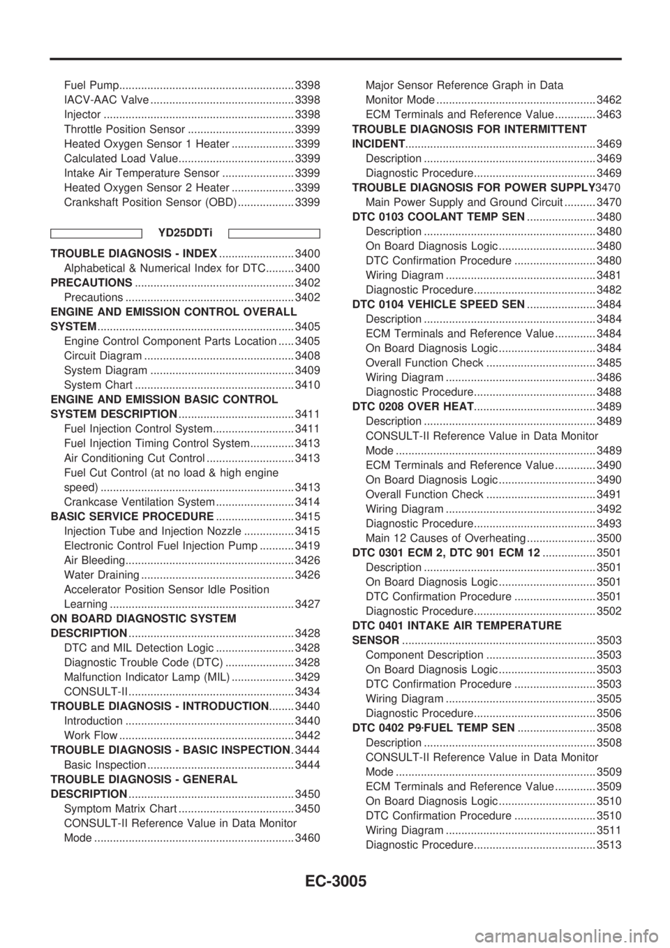
Fuel Pump........................................................ 3398
IACV-AAC Valve .............................................. 3398
Injector ............................................................. 3398
Throttle Position Sensor .................................. 3399
Heated Oxygen Sensor 1 Heater .................... 3399
Calculated Load Value..................................... 3399
Intake Air Temperature Sensor ....................... 3399
Heated Oxygen Sensor 2 Heater .................... 3399
Crankshaft Position Sensor (OBD) .................. 3399
YD25DDTi
TROUBLE DIAGNOSIS - INDEX........................ 3400
Alphabetical & Numerical Index for DTC......... 3400
PRECAUTIONS................................................... 3402
Precautions ...................................................... 3402
ENGINE AND EMISSION CONTROL OVERALL
SYSTEM............................................................... 3405
Engine Control Component Parts Location ..... 3405
Circuit Diagram ................................................ 3408
System Diagram .............................................. 3409
System Chart ................................................... 3410
ENGINE AND EMISSION BASIC CONTROL
SYSTEM DESCRIPTION..................................... 3411
Fuel Injection Control System.......................... 3411
Fuel Injection Timing Control System.............. 3413
Air Conditioning Cut Control ............................ 3413
Fuel Cut Control (at no load & high engine
speed) .............................................................. 3413
Crankcase Ventilation System ......................... 3414
BASIC SERVICE PROCEDURE......................... 3415
Injection Tube and Injection Nozzle ................ 3415
Electronic Control Fuel Injection Pump ........... 3419
Air Bleeding...................................................... 3426
Water Draining ................................................. 3426
Accelerator Position Sensor Idle Position
Learning ........................................................... 3427
ON BOARD DIAGNOSTIC SYSTEM
DESCRIPTION..................................................... 3428
DTC and MIL Detection Logic ......................... 3428
Diagnostic Trouble Code (DTC) ...................... 3428
Malfunction Indicator Lamp (MIL) .................... 3429
CONSULT-II ..................................................... 3434
TROUBLE DIAGNOSIS - INTRODUCTION........ 3440
Introduction ...................................................... 3440
Work Flow ........................................................ 3442
TROUBLE DIAGNOSIS - BASIC INSPECTION. 3444
Basic Inspection ............................................... 3444
TROUBLE DIAGNOSIS - GENERAL
DESCRIPTION..................................................... 3450
Symptom Matrix Chart ..................................... 3450
CONSULT-II Reference Value in Data Monitor
Mode ................................................................ 3460Major Sensor Reference Graph in Data
Monitor Mode ................................................... 3462
ECM Terminals and Reference Value ............. 3463
TROUBLE DIAGNOSIS FOR INTERMITTENT
INCIDENT............................................................. 3469
Description ....................................................... 3469
Diagnostic Procedure....................................... 3469
TROUBLE DIAGNOSIS FOR POWER SUPPLY3470
Main Power Supply and Ground Circuit .......... 3470
DTC 0103 COOLANT TEMP SEN...................... 3480
Description ....................................................... 3480
On Board Diagnosis Logic ............................... 3480
DTC Confirmation Procedure .......................... 3480
Wiring Diagram ................................................ 3481
Diagnostic Procedure....................................... 3482
DTC 0104 VEHICLE SPEED SEN...................... 3484
Description ....................................................... 3484
ECM Terminals and Reference Value ............. 3484
On Board Diagnosis Logic ............................... 3484
Overall Function Check ................................... 3485
Wiring Diagram ................................................ 3486
Diagnostic Procedure....................................... 3488
DTC 0208 OVER HEAT....................................... 3489
Description ....................................................... 3489
CONSULT-II Reference Value in Data Monitor
Mode ................................................................ 3489
ECM Terminals and Reference Value ............. 3490
On Board Diagnosis Logic ............................... 3490
Overall Function Check ................................... 3491
Wiring Diagram ................................................ 3492
Diagnostic Procedure....................................... 3493
Main 12 Causes of Overheating ...................... 3500
DTC 0301 ECM 2, DTC 901 ECM 12................. 3501
Description ....................................................... 3501
On Board Diagnosis Logic ............................... 3501
DTC Confirmation Procedure .......................... 3501
Diagnostic Procedure....................................... 3502
DTC 0401 INTAKE AIR TEMPERATURE
SENSOR.............................................................. 3503
Component Description ................................... 3503
On Board Diagnosis Logic ............................... 3503
DTC Confirmation Procedure .......................... 3503
Wiring Diagram ................................................ 3505
Diagnostic Procedure....................................... 3506
DTC 0402 P9zFUEL TEMP SEN......................... 3508
Description ....................................................... 3508
CONSULT-II Reference Value in Data Monitor
Mode ................................................................ 3509
ECM Terminals and Reference Value ............. 3509
On Board Diagnosis Logic ............................... 3510
DTC Confirmation Procedure .......................... 3510
Wiring Diagram ................................................ 3511
Diagnostic Procedure....................................... 3513
EC-3005
Page 32 of 1306

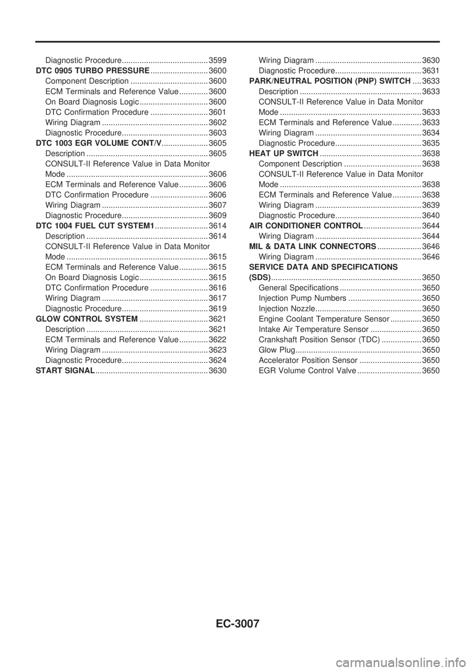
Diagnostic Procedure....................................... 3599
DTC 0905 TURBO PRESSURE.......................... 3600
Component Description ................................... 3600
ECM Terminals and Reference Value ............. 3600
On Board Diagnosis Logic ............................... 3600
DTC Confirmation Procedure .......................... 3601
Wiring Diagram ................................................ 3602
Diagnostic Procedure....................................... 3603
DTC 1003 EGR VOLUME CONT/V..................... 3605
Description ....................................................... 3605
CONSULT-II Reference Value in Data Monitor
Mode ................................................................ 3606
ECM Terminals and Reference Value ............. 3606
DTC Confirmation Procedure .......................... 3606
Wiring Diagram ................................................ 3607
Diagnostic Procedure....................................... 3609
DTC 1004 FUEL CUT SYSTEM1........................ 3614
Description ....................................................... 3614
CONSULT-II Reference Value in Data Monitor
Mode ................................................................ 3615
ECM Terminals and Reference Value ............. 3615
On Board Diagnosis Logic ............................... 3615
DTC Confirmation Procedure .......................... 3616
Wiring Diagram ................................................ 3617
Diagnostic Procedure....................................... 3619
GLOW CONTROL SYSTEM............................... 3621
Description ....................................................... 3621
ECM Terminals and Reference Value ............. 3622
Wiring Diagram ................................................ 3623
Diagnostic Procedure....................................... 3624
START SIGNAL................................................... 3630Wiring Diagram ................................................ 3630
Diagnostic Procedure....................................... 3631
PARK/NEUTRAL POSITION (PNP) SWITCH.... 3633
Description ....................................................... 3633
CONSULT-II Reference Value in Data Monitor
Mode ................................................................ 3633
ECM Terminals and Reference Value ............. 3633
Wiring Diagram ................................................ 3634
Diagnostic Procedure....................................... 3635
HEAT UP SWITCH.............................................. 3638
Component Description ................................... 3638
CONSULT-II Reference Value in Data Monitor
Mode ................................................................ 3638
ECM Terminals and Reference Value ............. 3638
Wiring Diagram ................................................ 3639
Diagnostic Procedure....................................... 3640
AIR CONDITIONER CONTROL.......................... 3644
Wiring Diagram ................................................ 3644
MIL & DATA LINK CONNECTORS.................... 3646
Wiring Diagram ................................................ 3646
SERVICE DATA AND SPECIFICATIONS
(SDS).................................................................... 3650
General Specifications ..................................... 3650
Injection Pump Numbers ................................. 3650
Injection Nozzle................................................ 3650
Engine Coolant Temperature Sensor .............. 3650
Intake Air Temperature Sensor ....................... 3650
Crankshaft Position Sensor (TDC) .................. 3650
Glow Plug......................................................... 3650
Accelerator Position Sensor ............................ 3650
EGR Volume Control Valve ............................. 3650
EC-3007
Page 48 of 1306

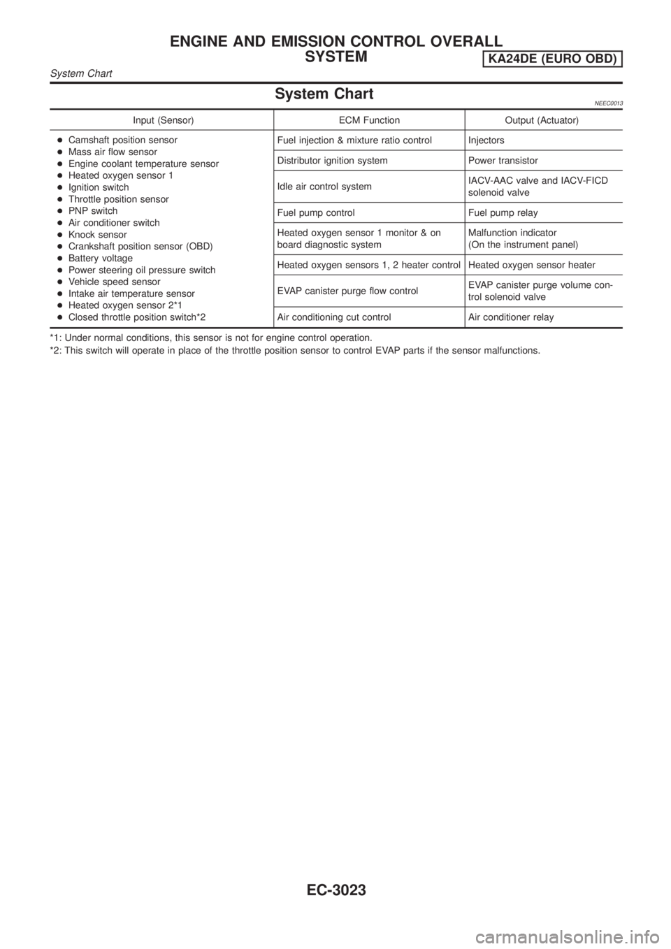
System ChartNEEC0013
Input (Sensor) ECM Function Output (Actuator)
+Camshaft position sensor
+Mass air flow sensor
+Engine coolant temperature sensor
+Heated oxygen sensor 1
+Ignition switch
+Throttle position sensor
+PNP switch
+Air conditioner switch
+Knock sensor
+Crankshaft position sensor (OBD)
+Battery voltage
+Power steering oil pressure switch
+Vehicle speed sensor
+Intake air temperature sensor
+Heated oxygen sensor 2*1
+Closed throttle position switch*2Fuel injection & mixture ratio control Injectors
Distributor ignition system Power transistor
Idle air control systemIACV-AAC valve and IACV-FICD
solenoid valve
Fuel pump control Fuel pump relay
Heated oxygen sensor 1 monitor & on
board diagnostic systemMalfunction indicator
(On the instrument panel)
Heated oxygen sensors 1, 2 heater control Heated oxygen sensor heater
EVAP canister purge flow controlEVAP canister purge volume con-
trol solenoid valve
Air conditioning cut control Air conditioner relay
*1: Under normal conditions, this sensor is not for engine control operation.
*2: This switch will operate in place of the throttle position sensor to control EVAP parts if the sensor malfunctions.
ENGINE AND EMISSION CONTROL OVERALL
SYSTEM
KA24DE (EURO OBD)
System Chart
EC-3023
Page 49 of 1306

Multiport Fuel Injection (MFI) System
DESCRIPTIONNEEC0014Input/Output Signal ChartNEEC0014S01
Sensor Input Signal to ECMECM func-
tionActuator
Camshaft position sensor Engine speed and piston position
Fuel injec-
tion & mix-
ture ratio
controlInjector Mass air flow sensor Amount of intake air
Engine coolant temperature sensor Engine coolant temperature
Heated oxygen sensor 1 Density of oxygen in exhaust gas
Throttle position sensorThrottle position
Throttle valve idle position
PNP switch Gear position
Vehicle speed sensor Vehicle speed
Ignition switch Start signal
Air conditioner switch Air conditioner operation
Knock sensor Engine knocking condition
Battery Battery voltage
Power steering oil pressure switch Power steering operation
Heated oxygen sensor 2* Density of oxygen in exhaust gas
* Under normal conditions, this sensor is not for engine control operation.
Basic Multiport Fuel Injection SystemNEEC0014S02The amount of fuel injected from the fuel injector is determined by the ECM. The ECM controls the length of
time the valve remains open (injection pulse duration). The amount of fuel injected is a program value in the
ECM memory. The program value is preset by engine operating conditions. These conditions are determined
by input signals (for engine speed and intake air) from both the camshaft position sensor and the mass air
flow sensor.
Various Fuel Injection Increase/Decrease CompensationNEEC0014S03In addition, the amount of fuel injected is compensated to improve engine performance under various oper-
ating conditions as listed below.
+During warm-up
+When starting the engine
+During acceleration
+Hot-engine operation
+High-load, high-speed operation
+During deceleration
+During high engine speed operation
ENGINE AND EMISSION BASIC CONTROL SYSTEM
DESCRIPTION
KA24DE (EURO OBD)
Multiport Fuel Injection (MFI) System
EC-3024
Page 50 of 1306

Mixture Ratio Feedback Control (Closed loop control)NEEC0014S04
SEC303D
The mixture ratio feedback system provides the best air-fuel mixture ratio for driveability and emission con-
trol. The three way catalyst can then better reduce CO, HC and NOx emissions. This system uses a heated
oxygen sensor 1 in the exhaust manifold to monitor if the engine operation is rich or lean. The ECM adjusts
the injection pulse width according to the sensor voltage signal. For more information about the heated oxy-
gen sensor 1, refer to EC-3213. This maintains the mixture ratio within the range of stoichiometric (ideal air-
fuel mixture).
This stage is referred to as the closed loop control condition.
Heated oxygen sensor 2 is located downstream of the three way catalyst. Even if the switching characteris-
tics of the heated oxygen sensor 1 shift, the air-fuel ratio is controlled to stoichiometric by the signal from the
heated oxygen sensor 2.
Open Loop ControlNEEC0014S05The open loop system condition refers to when the ECM detects any of the following conditions. Feedback
control stops in order to maintain stabilized fuel combustion.
+Deceleration and acceleration
+High-load, high-speed operation
+Malfunction of heated oxygen sensor 1 or its circuit
+Insufficient activation of heated oxygen sensor 1 at low engine coolant temperature
+High engine coolant temperature
+During warm-up
+When starting the engine
Mixture Ratio Self-learning ControlNEEC0014S06The mixture ratio feedback control system monitors the mixture ratio signal transmitted from the heated oxy-
gen sensor 1. This feedback signal is then sent to the ECM. The ECM controls the basic mixture ratio as close
to the theoretical mixture ratio as possible. However, the basic mixture ratio is not necessarily controlled as
originally designed. Both manufacturing differences (i.e., mass air flow sensor hot film) and characteristic
changes during operation (i.e., injector clogging) directly affect mixture ratio.
Accordingly, the difference between the basic and theoretical mixture ratios is monitored in this system. This
is then computed in terms of ªinjection pulse durationº to automatically compensate for the difference between
the two ratios.
ªFuel trimº refers to the feedback compensation value compared against the basic injection duration. Fuel trim
includes short term fuel trim and long term fuel trim.
ªShort term fuel trimº is the short-term fuel compensation used to maintain the mixture ratio at its theoretical
value. The signal from the heated oxygen sensor 1 indicates whether the mixture ratio is RICH or LEAN com-
pared to the theoretical value. The signal then triggers a reduction in fuel volume if the mixture ratio is rich,
and an increase in fuel volume if it is lean.
ªLong term fuel trimº is overall fuel compensation carried out long-term to compensate for continual deviation
of the short term fuel trim from the central value. Such deviation will occur due to individual engine differences,
wear over time and changes in the usage environment.
ENGINE AND EMISSION BASIC CONTROL SYSTEM
DESCRIPTION
KA24DE (EURO OBD)
Multiport Fuel Injection (MFI) System
EC-3025
Page 52 of 1306

System DescriptionNEEC0015S02
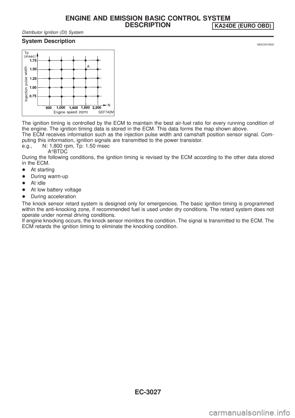
SEF742M
The ignition timing is controlled by the ECM to maintain the best air-fuel ratio for every running condition of
the engine. The ignition timing data is stored in the ECM. This data forms the map shown above.
The ECM receives information such as the injection pulse width and camshaft position sensor signal. Com-
puting this information, ignition signals are transmitted to the power transistor.
e.g., N: 1,800 rpm, Tp: 1.50 msec
AÉBTDC
During the following conditions, the ignition timing is revised by the ECM according to the other data stored
in the ECM.
+At starting
+During warm-up
+At idle
+At low battery voltage
+During acceleration
The knock sensor retard system is designed only for emergencies. The basic ignition timing is programmed
within the anti-knocking zone, if recommended fuel is used under dry conditions. The retard system does not
operate under normal driving conditions.
If engine knocking occurs, the knock sensor monitors the condition. The signal is transmitted to the ECM. The
ECM retards the ignition timing to eliminate the knocking condition.
ENGINE AND EMISSION BASIC CONTROL SYSTEM
DESCRIPTION
KA24DE (EURO OBD)
Distributor Ignition (DI) System
EC-3027