2001 NISSAN PICK-UP air condition
[x] Cancel search: air conditionPage 100 of 1306
![NISSAN PICK-UP 2001 Repair Manual Monitored item [Unit]ECM
input
signalsMain
signalsDescription Remarks
THRTL POS SEN [V]jj+The throttle position sensor signal volt-
age is displayed.
INT/A TEMP SE
[ÉC] or [ÉF]jj+The intake air temp NISSAN PICK-UP 2001 Repair Manual Monitored item [Unit]ECM
input
signalsMain
signalsDescription Remarks
THRTL POS SEN [V]jj+The throttle position sensor signal volt-
age is displayed.
INT/A TEMP SE
[ÉC] or [ÉF]jj+The intake air temp](/manual-img/5/57372/w960_57372-99.png)
Monitored item [Unit]ECM
input
signalsMain
signalsDescription Remarks
THRTL POS SEN [V]jj+The throttle position sensor signal volt-
age is displayed.
INT/A TEMP SE
[ÉC] or [ÉF]jj+The intake air temperature determined
by the signal voltage of the intake air
temperature sensor is indicated.
START SIGNAL
[ON/OFF]jj+Indicates [ON/OFF] condition from the
starter signal.+After starting the engine, [OFF] is dis-
played regardless of the starter sig-
nal.
CLSD THL POS
[ON/OFF]jj+Indicates idle position [ON/OFF] com-
puted by ECM according to the throttle
position sensor signal.
CLSD THL/P SW
[ON/OFF]j+Indicates mechanical contact [ON/OFF]
condition of the closed throttle position
switch.
AIR COND SIG
[ON/OFF]jj+Indicates [ON/OFF] condition of the air
conditioner switch as determined by
the air conditioning signal.
P/N POSI SW
[ON/OFF]jj+Indicates [ON/OFF] condition from the
PNP switch signal.
PW/ST SIGNAL
[ON/OFF]jj+Indicates [ON/OFF] condition of the
power steering oil pressure switch
determined by the power steering oil
pressure switch signal.
AMB TEMP SW
[ON/OFF]j+Indicates [ON/OFF] condition from the
ambient air temperature switch signal.
IGNITION SW
[ON/OFF]j+Indicates [ON/OFF] condition from igni-
tion switch.
INJ PULSE-B1 [msec]j+Indicates the actual fuel injection pulse
width compensated by ECM according
to the input signals.+When the engine is stopped, a cer-
tain computed value is indicated.
IGN TIMING [BTDC]j+Indicates the ignition timing computed
by ECM according to the input signals.
CAL/LD VALUE [%]+ªCalculated load valueº indicates the
value of the current airflow divided by
peak airflow.
ABSOL TH´P/S [%]+ªAbsolute throttle position sensorº indi-
cates the throttle opening computed by
ECM according to the signal voltage of
the throttle position sensor.
MASS AIRFLOW
[g´m/s]+Indicates the mass airflow computed by
ECM according to the signal voltage of
the mass air flow sensor.
IACV-AAC/V [%]j+Indicates the IACV-AAC valve control
value computed by ECM according to
the input signals.
PURG VOL C/V [%]+Indicates the EVAP canister purge vol-
ume control value computed by the
ECM according to the input signals.
+The opening becomes larger as the
value increases.
ON BOARD DIAGNOSTIC SYSTEM
DESCRIPTION
KA24DE (EURO OBD)
CONSULT-II
EC-3075
Page 101 of 1306
![NISSAN PICK-UP 2001 Repair Manual Monitored item [Unit]ECM
input
signalsMain
signalsDescription Remarks
AIR COND RLY
[ON/OFF]j+Indicates the air conditioner relay con-
trol condition determined by ECM
according to the input signals.
F NISSAN PICK-UP 2001 Repair Manual Monitored item [Unit]ECM
input
signalsMain
signalsDescription Remarks
AIR COND RLY
[ON/OFF]j+Indicates the air conditioner relay con-
trol condition determined by ECM
according to the input signals.
F](/manual-img/5/57372/w960_57372-100.png)
Monitored item [Unit]ECM
input
signalsMain
signalsDescription Remarks
AIR COND RLY
[ON/OFF]j+Indicates the air conditioner relay con-
trol condition determined by ECM
according to the input signals.
FUEL PUMP RLY
[ON/OFF]j+Indicates the fuel pump relay control
condition determined by ECM accord-
ing to the input signals.
HO2S1 HTR (B1)
[ON/OFF]+Indicates [ON/OFF] condition of heated
oxygen sensor 1 heater determined by
ECM according to the input signals.
HO2S2 HTR (B1)
[ON/OFF]+Indicates [ON/OFF] condition of heated
oxygen sensor 2 heater determined by
ECM according to the input signals.
VOLTAGE [V]+Voltage measured by the voltage
probe.
TRVL AFTER MIL
[km] or [Mile]+Distance traveled while MI is activated.
Frequency
[msec] or [Hz] or [%]+Pulse width, frequency or duty cycle
measured by the pulse probe.+Only ª#º is displayed if item is unable
to be measured.
+Figures with ª#ºs are temporary ones.
They are the same figures as an
actual piece of data which was just
previously measured.
NOTE:
Any monitored item that does not match the vehicle being diagnosed is deleted from the display automatically.
DATA MONITOR (SPEC) MODENEEC0034S12
Monitored item [Unit]ECM
input
signalsMain
signalsDescription Remarks
ENG SPEED [rpm]jj+Indicates the engine speed computed
from the REF signal (180É signal) of
the camshaft position sensor.
MAS A/F SE-B1 [V]jj+The signal voltage of the mass air flow
sensor specification is displayed.+When engine is running specification
range is indicated.
B/FUEL SCHDL
[msec]j+ªBase fuel scheduleº indicates the fuel
injection pulse width programmed into
ECM, prior to any learned on board
correction.+When engine is running specification
range is indicated.
A/F ALPHA-B1 [%]j+The mean value of the air-fuel ratio
feedback correction factor per cycle is
indicated.+When engine is running specification
range is indicated.
+This data also includes the data for the
air-fuel ratio learning control.
NOTE:
Any monitored item that does not match the vehicle being diagnosed is deleted from the display automatically.
ACTIVE TEST MODENEEC0034S07
TEST ITEM CONDITION JUDGEMENT CHECK ITEM (REMEDY)
FUEL INJECTION+Engine: Return to the original
trouble condition
+Change the amount of fuel injec-
tion using CONSULT-II.If trouble symptom disappears, see
CHECK ITEM.+Harness and connector
+Fuel injectors
+Heated oxygen sensor 1
ON BOARD DIAGNOSTIC SYSTEM
DESCRIPTION
KA24DE (EURO OBD)
CONSULT-II
EC-3076
Page 102 of 1306
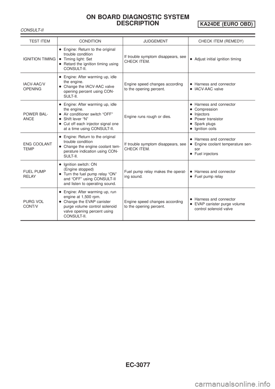
TEST ITEM CONDITION JUDGEMENT CHECK ITEM (REMEDY)
IGNITION TIMING+Engine: Return to the original
trouble condition
+Timing light: Set
+Retard the ignition timing using
CONSULT-II.If trouble symptom disappears, see
CHECK ITEM.+Adjust initial ignition timing
IACV-AAC/V
OPENING+Engine: After warming up, idle
the engine.
+Change the IACV-AAC valve
opening percent using CON-
SULT-II.Engine speed changes according
to the opening percent.+Harness and connector
+IACV-AAC valve
POWER BAL-
ANCE+Engine: After warming up, idle
the engine.
+Air conditioner switch ªOFFº
+Shift lever ªNº
+Cut off each injector signal one
at a time using CONSULT-II.Engine runs rough or dies.+Harness and connector
+Compression
+Injectors
+Power transistor
+Spark plugs
+Ignition coils
ENG COOLANT
TEMP+Engine: Return to the original
trouble condition
+Change the engine coolant tem-
perature indication using CON-
SULT-II.If trouble symptom disappears, see
CHECK ITEM.+Harness and connector
+Engine coolant temperature sen-
sor
+Fuel injectors
FUEL PUMP
RELAY+Ignition switch: ON
(Engine stopped)
+Turn the fuel pump relay ªONº
and ªOFFº using CONSULT-II
and listen to operating sound.Fuel pump relay makes the operat-
ing sound.+Harness and connector
+Fuel pump relay
PURG VOL
CONT/V+Engine: After warming up, run
engine at 1,500 rpm.
+Change the EVAP canister
purge volume control solenoid
valve opening percent using
CONSULT-II.Engine speed changes according
to the opening percent.+Harness and connector
+EVAP canister purge volume
control solenoid valve
ON BOARD DIAGNOSTIC SYSTEM
DESCRIPTION
KA24DE (EURO OBD)
CONSULT-II
EC-3077
Page 107 of 1306
MEF036D
IntroductionNEEC0036
SEF233G
SEF234G
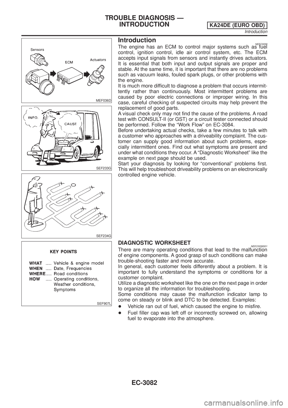
The engine has an ECM to control major systems such as fuel
control, ignition control, idle air control system, etc. The ECM
accepts input signals from sensors and instantly drives actuators.
It is essential that both input and output signals are proper and
stable. At the same time, it is important that there are no problems
such as vacuum leaks, fouled spark plugs, or other problems with
the engine.
It is much more difficult to diagnose a problem that occurs intermit-
tently rather than continuously. Most intermittent problems are
caused by poor electric connections or improper wiring. In this
case, careful checking of suspected circuits may help prevent the
replacement of good parts.
A visual check only may not find the cause of the problems. A road
test with CONSULT-II (or GST) or a circuit tester connected should
be performed. Follow the ªWork Flowº on EC-3084.
Before undertaking actual checks, take a few minutes to talk with
a customer who approaches with a driveability complaint. The cus-
tomer can supply good information about such problems, espe-
cially intermittent ones. Find out what symptoms are present and
under what conditions they occur. A ªDiagnostic Worksheetº like the
example on next page should be used.
Start your diagnosis by looking for ªconventionalº problems first.
This will help troubleshoot driveability problems on an electronically
controlled engine vehicle.
SEF907L
DIAGNOSTIC WORKSHEETNEEC0036S01There are many operating conditions that lead to the malfunction
of engine components. A good grasp of such conditions can make
trouble-shooting faster and more accurate.
In general, each customer feels differently about a problem. It is
important to fully understand the symptoms or conditions for a
customer complaint.
Utilize a diagnostic worksheet like the one on the next page in order
to organize all the information for troubleshooting.
Some conditions may cause the malfunction indicator lamp to
come on steady or blink and DTC to be detected. Examples:
+Vehicle ran out of fuel, which caused the engine to misfire.
+Fuel filler cap was left off or incorrectly screwed on, allowing
fuel to evaporate into the atmosphere.
TROUBLE DIAGNOSIS Ð
INTRODUCTION
KA24DE (EURO OBD)
Introduction
EC-3082
Page 110 of 1306
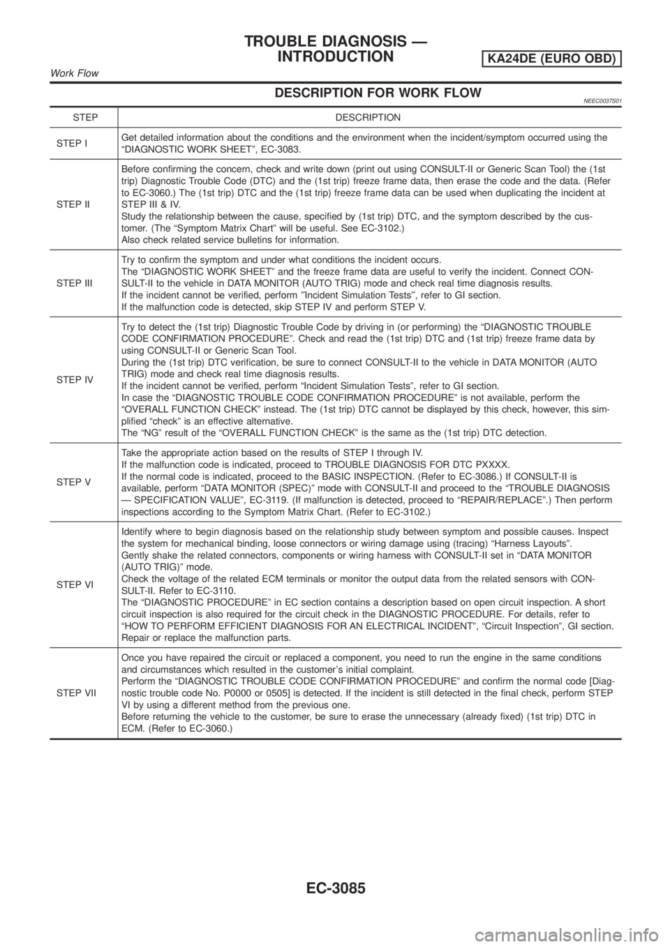
DESCRIPTION FOR WORK FLOWNEEC0037S01
STEP DESCRIPTION
STEP IGet detailed information about the conditions and the environment when the incident/symptom occurred using the
ªDIAGNOSTIC WORK SHEETº, EC-3083.
STEP IIBefore confirming the concern, check and write down (print out using CONSULT-II or Generic Scan Tool) the (1st
trip) Diagnostic Trouble Code (DTC) and the (1st trip) freeze frame data, then erase the code and the data. (Refer
to EC-3060.) The (1st trip) DTC and the (1st trip) freeze frame data can be used when duplicating the incident at
STEP III & IV.
Study the relationship between the cause, specified by (1st trip) DTC, and the symptom described by the cus-
tomer. (The ªSymptom Matrix Chartº will be useful. See EC-3102.)
Also check related service bulletins for information.
STEP IIITry to confirm the symptom and under what conditions the incident occurs.
The ªDIAGNOSTIC WORK SHEETº and the freeze frame data are useful to verify the incident. Connect CON-
SULT-II to the vehicle in DATA MONITOR (AUTO TRIG) mode and check real time diagnosis results.
If the incident cannot be verified, perform²Incident Simulation Tests², refer to GI section.
If the malfunction code is detected, skip STEP IV and perform STEP V.
STEP IVTry to detect the (1st trip) Diagnostic Trouble Code by driving in (or performing) the ªDIAGNOSTIC TROUBLE
CODE CONFIRMATION PROCEDUREº. Check and read the (1st trip) DTC and (1st trip) freeze frame data by
using CONSULT-II or Generic Scan Tool.
During the (1st trip) DTC verification, be sure to connect CONSULT-II to the vehicle in DATA MONITOR (AUTO
TRIG) mode and check real time diagnosis results.
If the incident cannot be verified, perform ªIncident Simulation Testsº, refer to GI section.
In case the ªDIAGNOSTIC TROUBLE CODE CONFIRMATION PROCEDUREº is not available, perform the
ªOVERALL FUNCTION CHECKº instead. The (1st trip) DTC cannot be displayed by this check, however, this sim-
plified ªcheckº is an effective alternative.
The ªNGº result of the ªOVERALL FUNCTION CHECKº is the same as the (1st trip) DTC detection.
STEP VTake the appropriate action based on the results of STEP I through IV.
If the malfunction code is indicated, proceed to TROUBLE DIAGNOSIS FOR DTC PXXXX.
If the normal code is indicated, proceed to the BASIC INSPECTION. (Refer to EC-3086.) If CONSULT-II is
available, perform ªDATA MONITOR (SPEC)º mode with CONSULT-II and proceed to the ªTROUBLE DIAGNOSIS
Ð SPECIFICATION VALUEº, EC-3119. (If malfunction is detected, proceed to ªREPAIR/REPLACEº.) Then perform
inspections according to the Symptom Matrix Chart. (Refer to EC-3102.)
STEP VIIdentify where to begin diagnosis based on the relationship study between symptom and possible causes. Inspect
the system for mechanical binding, loose connectors or wiring damage using (tracing) ªHarness Layoutsº.
Gently shake the related connectors, components or wiring harness with CONSULT-II set in ªDATA MONITOR
(AUTO TRIG)º mode.
Check the voltage of the related ECM terminals or monitor the output data from the related sensors with CON-
SULT-II. Refer to EC-3110.
The ªDIAGNOSTIC PROCEDUREº in EC section contains a description based on open circuit inspection. A short
circuit inspection is also required for the circuit check in the DIAGNOSTIC PROCEDURE. For details, refer to
ªHOW TO PERFORM EFFICIENT DIAGNOSIS FOR AN ELECTRICAL INCIDENTº, ªCircuit Inspectionº, GI section.
Repair or replace the malfunction parts.
STEP VIIOnce you have repaired the circuit or replaced a component, you need to run the engine in the same conditions
and circumstances which resulted in the customer's initial complaint.
Perform the ªDIAGNOSTIC TROUBLE CODE CONFIRMATION PROCEDUREº and confirm the normal code [Diag-
nostic trouble code No. P0000 or 0505] is detected. If the incident is still detected in the final check, perform STEP
VI by using a different method from the previous one.
Before returning the vehicle to the customer, be sure to erase the unnecessary (already fixed) (1st trip) DTC in
ECM. (Refer to EC-3060.)
TROUBLE DIAGNOSIS Ð
INTRODUCTION
KA24DE (EURO OBD)
Work Flow
EC-3085
Page 111 of 1306

Basic InspectionNEEC0038Precaution:
Perform Basic Inspection without electrical or mechanical
loads applied;
+Headlamp switch is OFF,
+Air conditioner switch is OFF,
+Rear window defogger switch is OFF,
+Steering wheel is in the straight-ahead position, etc.
1 INSPECTION START
1. Check service records for any recent repairs that may indicate a related problem, or the current need for scheduled
maintenance.
2. Open engine hood and check the following:
+Harness connectors for improper connections
+Vacuum hoses for splits, kinks, or improper connections
+Wiring for improper connections, pinches, or cuts
SEF142I
With CONSULT-II©GO TO 2.
With GST©GO TO 4.
No tools©GO TO 5.
2 CONNECT CONSULT-II TO THE VEHICLE
Connect ªCONSULT-IIº to the data link connector and select ªENGINEº from the menu. Refer to EC-3070.
SEC305D
©GO TO 3.
TROUBLE DIAGNOSIS Ð BASIC
INSPECTION
KA24DE (EURO OBD)
Basic Inspection
EC-3086
Page 126 of 1306
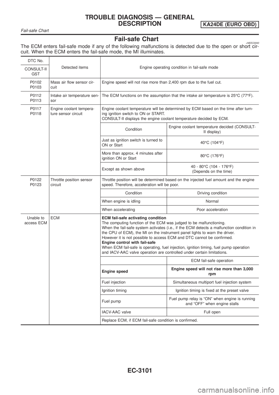
Fail-safe Chart=NEEC0040The ECM enters fail-safe mode if any of the following malfunctions is detected due to the open or short cir-
cuit. When the ECM enters the fail-safe mode, the MI illuminates.
DTC No.
Detected items Engine operating condition in fail-safe mode
CONSULT-II
GST
P0102
P0103Mass air flow sensor cir-
cuitEngine speed will not rise more than 2,400 rpm due to the fuel cut.
P0112
P0113Intake air temperature sen-
sorThe ECM functions on the assumption that the intake air temperature is 25ÉC (77ÉF).
P0117
P0118Engine coolant tempera-
ture sensor circuitEngine coolant temperature will be determined by ECM based on the time after turn-
ing ignition switch to ON or START.
CONSULT-II displays the engine coolant temperature decided by ECM.
ConditionEngine coolant temperature decided (CONSULT-
II display)
Just as ignition switch is turned to
ON or Start40ÉC (104ÉF)
More than approx. 4 minutes after
ignition ON or Start80ÉC (176ÉF)
Except as shown above40 - 80ÉC (104 - 176ÉF)
(Depends on the time)
P0122
P0123Throttle position sensor
circuitThrottle position will be determined based on the injected fuel amount and the engine
speed. Therefore, acceleration will be poor.
Condition Driving condition
When engine is idling Normal
When accelerating Poor acceleration
Unable to
access ECMECMECM fail-safe activating condition
The computing function of the ECM was judged to be malfunctioning.
When the fail-safe system activates (i.e., if the ECM detects a malfunction condition in
the CPU of ECM), the MI on the instrument panel lights to warn the driver.
However it is not possible to access ECM and DTC cannot be confirmed.
Engine control with fail-safe
When ECM fail-safe is operating, fuel injection, ignition timing, fuel pump operation
and IACV-AAC valve operation are controlled under certain limitations.
ECM fail-safe operation
Engine speedEngine speed will not rise more than 3,000
rpm
Fuel injection Simultaneous multiport fuel injection system
Ignition timing Ignition timing is fixed at the preset valve
Fuel pumpFuel pump relay is ªONº when engine is running
and ªOFFº when engine stalls
IACV-AAC valve Full open
Replace ECM, if ECM fail-safe condition is confirmed.
TROUBLE DIAGNOSIS Ð GENERAL
DESCRIPTION
KA24DE (EURO OBD)
Fail-safe Chart
EC-3101
Page 127 of 1306
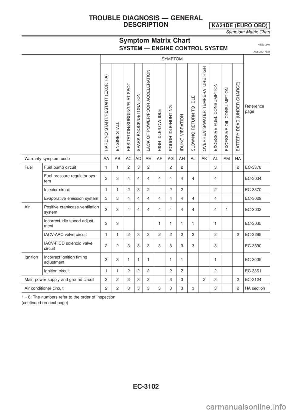
Symptom Matrix ChartNEEC0041SYSTEM Ð ENGINE CONTROL SYSTEMNEEC0041S01
SYMPTOM
Reference
page
HARD/NO START/RESTART (EXCP. HA)
ENGINE STALL
HESITATION/SURGING/FLAT SPOT
SPARK KNOCK/DETONATION
LACK OF POWER/POOR ACCELERATION
HIGH IDLE/LOW IDLE
ROUGH IDLE/HUNTING
IDLING VIBRATION
SLOW/NO RETURN TO IDLE
OVERHEATS/WATER TEMPERATURE HIGH
EXCESSIVE FUEL CONSUMPTION
EXCESSIVE OIL CONSUMPTION
BATTERY DEAD (UNDER CHARGE)
Warranty symptom code AA AB AC AD AE AF AG AH AJ AK AL AM HA
Fuel Fuel pump circuit 1 1 2 3 2 2 2 3 2 EC-3378
Fuel pressure regulator sys-
tem334444444 4EC-3034
Injector circuit 1 1 2 3 2 2 2 2 EC-3370
Evaporative emission system 3 3 4 444444 4EC-3029
Air Positive crankcase ventilation
system334444444 41EC-3032
Incorrect idle speed adjust-
ment33 1111 1EC-3035
IACV-AAC valve circuit 1 1 2 332222 2 2EC-3295
IACV-FICD solenoid valve
circuit223333333 3EC-3390
Ignition Incorrect ignition timing
adjustment3 3 1 1 1 1 1 1 EC-3035
Ignition circuit 1 1 2 2 2 2 2 2 EC-3361
Main power supply and ground circuit 2 2 3 3 3 3 3 2 3 2 EC-3124
Air conditioner circuit 2 2 3 333333 3 2HAsection
1 - 6: The numbers refer to the order of inspection.
(continued on next page)
TROUBLE DIAGNOSIS Ð GENERAL
DESCRIPTION
KA24DE (EURO OBD)
Symptom Matrix Chart
EC-3102