2001 NISSAN PICK-UP air condition
[x] Cancel search: air conditionPage 269 of 1306
On Board Diagnosis LogicNEEC0192With the Air/Fuel Mixture Ratio Self-Learning Control, the actual mixture ratio can be brought closely to the
theoretical mixture ratio based on the mixture ratio feedback signal from the heated oxygen sensor 1. The ECM
calculates the necessary compensation to correct the offset between the actual and the theoretical ratios.
In case the amount of the compensation value is extremely large (The actual mixture ratio is too rich.), the
ECM judges the condition as the fuel injection system malfunction and lights up the MI (2 trip detection logic).
Sensor Input Signal to ECMECM func-
tionActuator
Heated oxygen sensor 1Density of oxygen in exhaust gas
(Mixture ratio feedback signal)Fuel injec-
tion & mix-
ture ratio
controlInjectors
DTC No. Malfunction is detected when ... Check Items (Possible Cause)
P0172
0172+Fuel injection system does not operate properly.
+The amount of mixture ratio compensation is too large.
(The mixture ratio is too rich.)+Heated oxygen sensor 1
+Injectors
+Exhaust gas leaks
+Incorrect fuel pressure
+Mass air flow sensor
SEF215Z
SEF058Y
DTC Confirmation ProcedureNEEC0193NOTE:
If ªDTC Confirmation Procedureº has been previously conducted,
always turn ignition switch OFF and wait at least 5 seconds before
conducting the next test.
With CONSULT-II
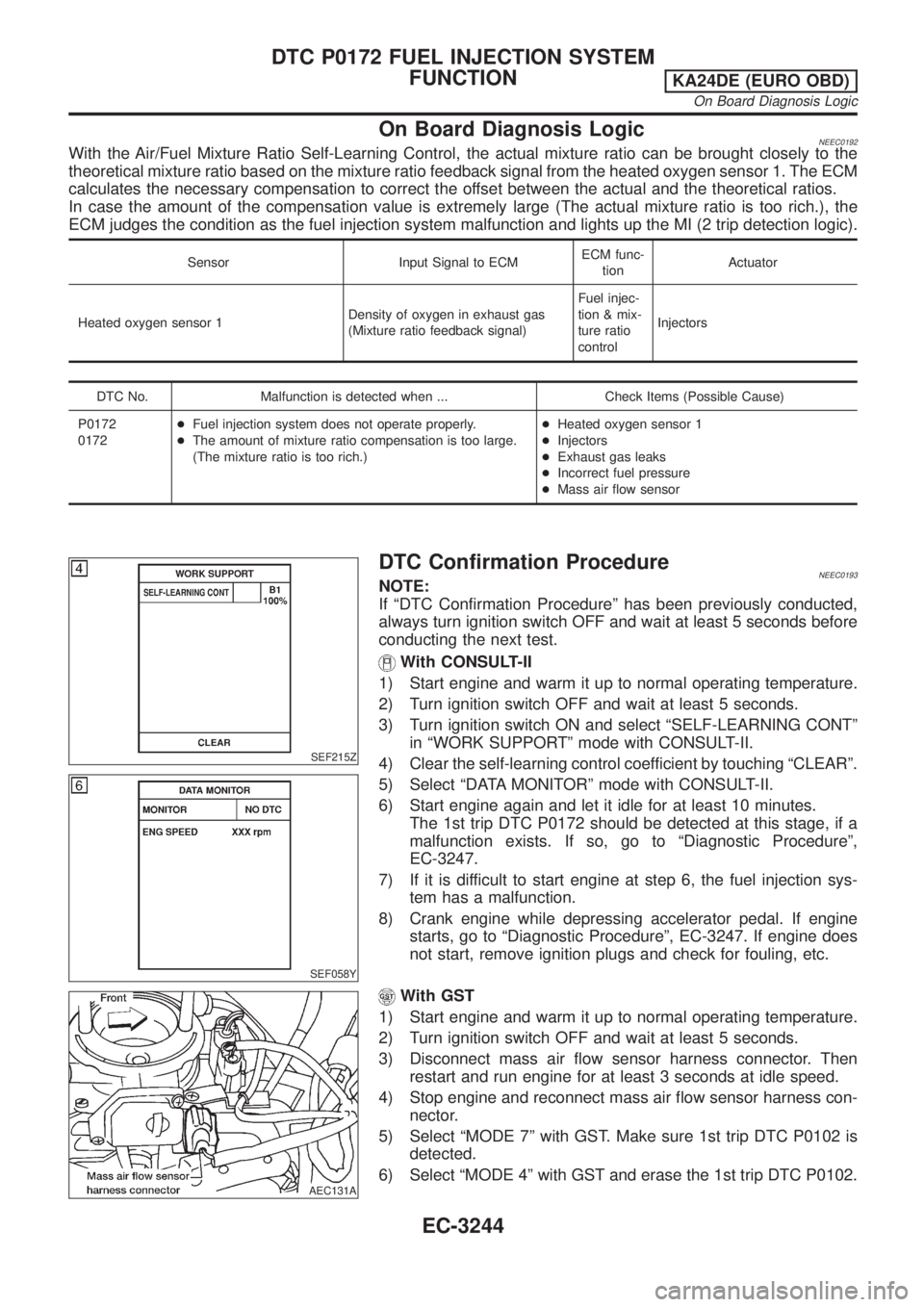
1) Start engine and warm it up to normal operating temperature.
2) Turn ignition switch OFF and wait at least 5 seconds.
3) Turn ignition switch ON and select ªSELF-LEARNING CONTº
in ªWORK SUPPORTº mode with CONSULT-II.
4) Clear the self-learning control coefficient by touching ªCLEARº.
5) Select ªDATA MONITORº mode with CONSULT-II.
6) Start engine again and let it idle for at least 10 minutes.
The 1st trip DTC P0172 should be detected at this stage, if a
malfunction exists. If so, go to ªDiagnostic Procedureº,
EC-3247.
7) If it is difficult to start engine at step 6, the fuel injection sys-
tem has a malfunction.
8) Crank engine while depressing accelerator pedal. If engine
starts, go to ªDiagnostic Procedureº, EC-3247. If engine does
not start, remove ignition plugs and check for fouling, etc.
AEC131A
With GST
1) Start engine and warm it up to normal operating temperature.
2) Turn ignition switch OFF and wait at least 5 seconds.
3) Disconnect mass air flow sensor harness connector. Then
restart and run engine for at least 3 seconds at idle speed.
4) Stop engine and reconnect mass air flow sensor harness con-
nector.
5) Select ªMODE 7º with GST. Make sure 1st trip DTC P0102 is
detected.
6) Select ªMODE 4º with GST and erase the 1st trip DTC P0102.
DTC P0172 FUEL INJECTION SYSTEM
FUNCTION
KA24DE (EURO OBD)
On Board Diagnosis Logic
EC-3244
Page 276 of 1306
On Board Diagnosis LogicNEEC0202When a misfire occurs, engine speed will fluctuate. If the engine speed fluctuates enough to cause the CKP
sensor signal to vary, the ECM can determine that a misfire is occurring.
Sensor Input Signal to ECM ECM function
Crankshaft position sensor (OBD) Engine speed On board diagnosis of misfire
The misfire detection logic consists of the following two conditions.
1. One Trip Detection Logic (Three Way Catalyst Damage)
On the first trip that a misfire condition occurs that can damage the three way catalyst (TWC) due to
overheating, the MI will blink.
When a misfire condition occurs, the ECM monitors the CKP sensor signal every 200 engine revolutions
for a change.
When the misfire condition decreases to a level that will not damage the TWC, the MI will turn off.
If another misfire condition occurs that can damage the TWC on a second trip, the MI will blink.
When the misfire condition decreases to a level that will not damage the TWC, the MI will remain on.
If another misfire condition occurs that can damage the TWC, the MI will begin to blink again.
2. Two Trip Detection Logic (Exhaust quality deterioration)
For misfire conditions that will not damage the TWC (but will affect vehicle emissions), the MI will only light
when the misfire is detected on a second trip. During this condition, the ECM monitors the CKP sensor
signal every 1,000 engine revolutions.
A misfire malfunction can be detected on any one cylinder or on multiple cylinders.
DTC No. Malfunction is detected when ... Check Items (Possible Cause)
P0300
0300+Multiple cylinders misfire.+Improper spark plug
+Insufficient compression
+Incorrect fuel pressure
+The injector circuit is open or shorted
+Injectors
+Intake air leak
+The ignition secondary circuit is open or shorted
+Lack of fuel
+Drive plate/Flywheel
+Heated oxygen sensor 1
+Incorrect distributor rotor P0301
0301+No. 1 cylinder misfires.
P0302
0302+No. 2 cylinder misfires.
P0303
0303+No. 3 cylinder misfires.
P0304
0304+No. 4 cylinder misfires.
SEF174Y
DTC Confirmation ProcedureNEEC0203CAUTION:
Always drive vehicle at a safe speed.
NOTE:
If ªDTC Confirmation Procedureº has been previously conducted,
always turn ignition switch OFF and wait at least 5 seconds before
conducting the next test.
With CONSULT-II
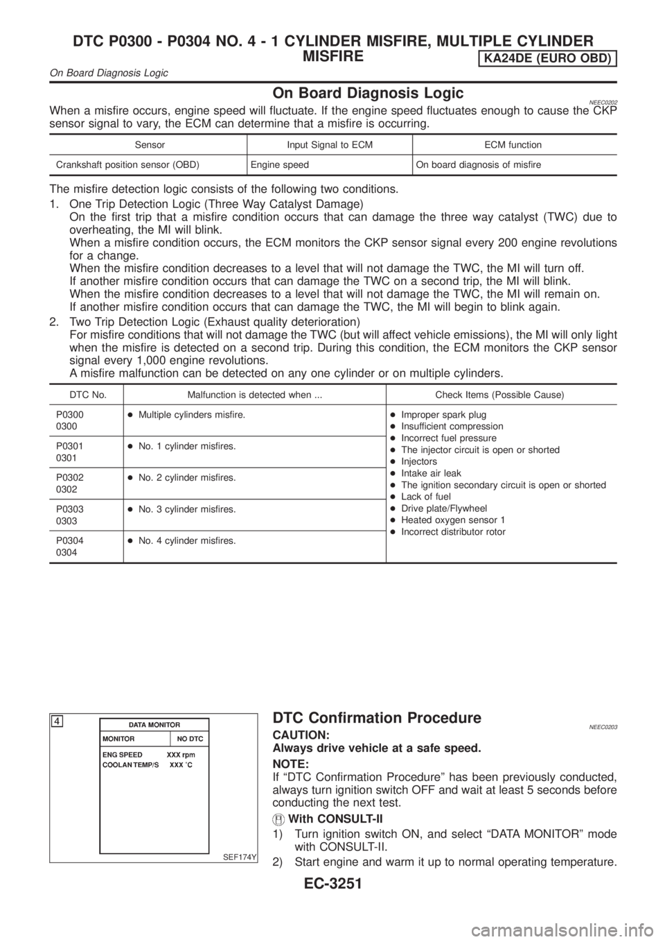
1) Turn ignition switch ON, and select ªDATA MONITORº mode
with CONSULT-II.
2) Start engine and warm it up to normal operating temperature.
DTC P0300 - P0304 NO.4-1CYLINDER MISFIRE, MULTIPLE CYLINDER
MISFIRE
KA24DE (EURO OBD)
On Board Diagnosis Logic
EC-3251
Page 277 of 1306
3) Turn ignition switch OFF and wait at least 5 seconds.
4) Start engine again and drive at 1,500 to 3,000 rpm for at least
3 minutes.
Hold the accelerator pedal as steady as possible.
NOTE:
Refer to the freeze frame data for the test driving conditions.
5) If 1st trip DTC is detected, go to ªDiagnostic Procedureº,
EC-3252.
With GST
Follow the procedure ªWith CONSULT-IIº.
Diagnostic ProcedureNEEC0204
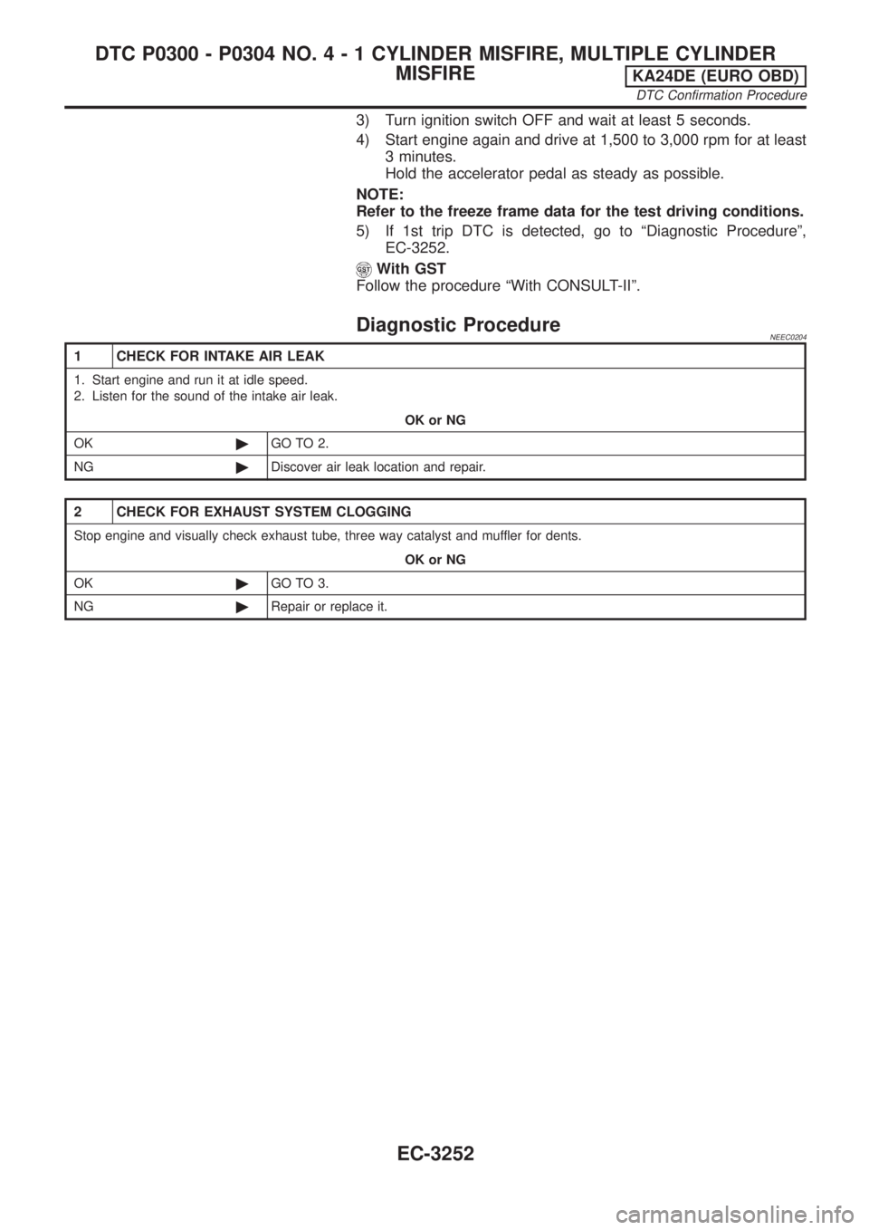
1 CHECK FOR INTAKE AIR LEAK
1. Start engine and run it at idle speed.
2. Listen for the sound of the intake air leak.
OK or NG
OK©GO TO 2.
NG©Discover air leak location and repair.
2 CHECK FOR EXHAUST SYSTEM CLOGGING
Stop engine and visually check exhaust tube, three way catalyst and muffler for dents.
OK or NG
OK©GO TO 3.
NG©Repair or replace it.
DTC P0300 - P0304 NO.4-1CYLINDER MISFIRE, MULTIPLE CYLINDER
MISFIRE
KA24DE (EURO OBD)
DTC Confirmation Procedure
EC-3252
Page 295 of 1306
SEF928V
SEF853B
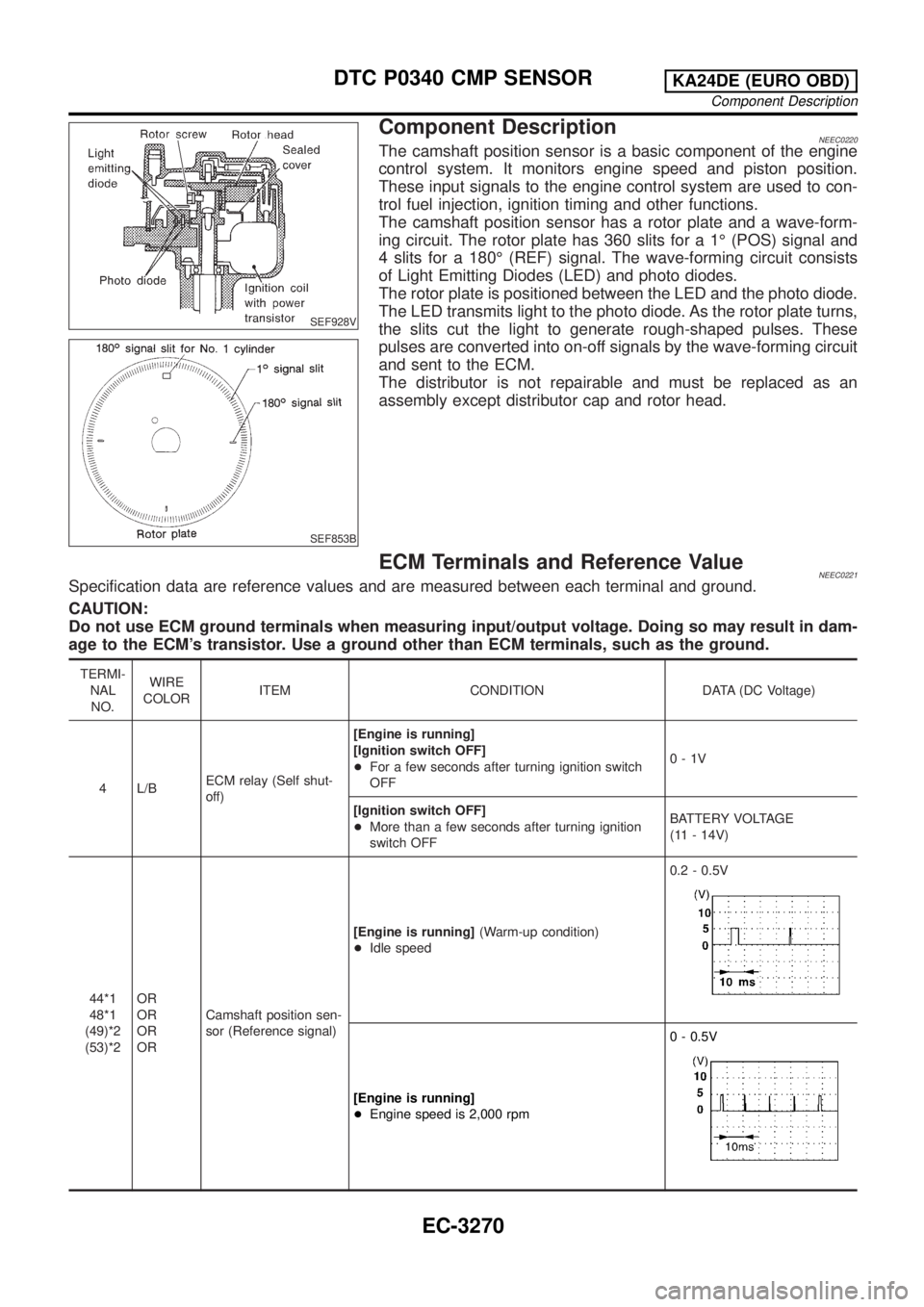
Component DescriptionNEEC0220The camshaft position sensor is a basic component of the engine
control system. It monitors engine speed and piston position.
These input signals to the engine control system are used to con-
trol fuel injection, ignition timing and other functions.
The camshaft position sensor has a rotor plate and a wave-form-
ing circuit. The rotor plate has 360 slits for a 1É (POS) signal and
4 slits for a 180É (REF) signal. The wave-forming circuit consists
of Light Emitting Diodes (LED) and photo diodes.
The rotor plate is positioned between the LED and the photo diode.
The LED transmits light to the photo diode. As the rotor plate turns,
the slits cut the light to generate rough-shaped pulses. These
pulses are converted into on-off signals by the wave-forming circuit
and sent to the ECM.
The distributor is not repairable and must be replaced as an
assembly except distributor cap and rotor head.
ECM Terminals and Reference ValueNEEC0221Specification data are reference values and are measured between each terminal and ground.
CAUTION:
Do not use ECM ground terminals when measuring input/output voltage. Doing so may result in dam-
age to the ECM's transistor. Use a ground other than ECM terminals, such as the ground.
TERMI-
NAL
NO.WIRE
COLORITEM CONDITION DATA (DC Voltage)
4 L/BECM relay (Self shut-
off)[Engine is running]
[Ignition switch OFF]
+For a few seconds after turning ignition switch
OFF0-1V
[Ignition switch OFF]
+More than a few seconds after turning ignition
switch OFFBATTERY VOLTAGE
(11 - 14V)
44*1
48*1
(49)*2
(53)*2OR
OR
OR
ORCamshaft position sen-
sor (Reference signal)[Engine is running](Warm-up condition)
+Idle speed0.2 - 0.5V
[Engine is running]
+Engine speed is 2,000 rpm0 - 0.5V
DTC P0340 CMP SENSORKA24DE (EURO OBD)
Component Description
EC-3270
Page 303 of 1306

SEF484YE
On Board Diagnosis LogicNEEC1050The ECM monitors the switching frequency ratio of heated oxygen
sensor 1 and 2.
A three way catalyst with high oxygen storage capacity will indicate
a low switching frequency of heated oxygen sensor 2. As oxygen
storage capacity decreases, the heated oxygen sensor 2 switching
frequency will increase.
When the frequency ratio of heated oxygen sensors 1 and 2
approaches a specified limit value, the three way catalyst malfunc-
tion is diagnosed.
DTC No. Malfunction is detected when ... Check Items (Possible Cause)
P0420
0420+Three way catalyst does not operate properly.
+Three way catalyst does not have enough oxygen stor-
age capacity.+Three way catalyst
+Exhaust tube
+Intake air leaks
+Injectors
+Injector leaks
+Spark plug
+Improper ignition timing
PBIB0566E
PBIB0567E
DTC Confirmation ProcedureNEEC1051NOTE:
If ªDTC Confirmation Procedureº has been previously
conducted, always turn ignition switch ªOFFº and wait at least
5 seconds before conducting the next test.
TESTING CONDITION:
+Open engine hood before conducting following proce-
dure.
+Do not hold engine speed more than specified minutes
below.
With CONSULT-II
1) Turn ignition switch ªONº.
2) Select ªDTC & SRT CONFIRMATIONº then ªSRT WORK SUP-
PORTº mode with CONSULT-II.
3) Start engine.
4) Rev engine up to 2,500 to 3,500 rpm and hold it for 3 consecu-
tive minutes then release then accelerator pedal completely.
If ªINCMPº of ªCATALYSTº changes to ªCMPLTº, go to step 7.
5) Wait 5 seconds at idle.
6) Rev engine up to 2,500 to 3,500 rpm and hold it until ªINCMPº
of ªCATALYSTº changes to ªCMPLTº. (It will take maximum of
approximately 5 minute.)
SEF560X
7) Select ªSELF-DIAG RESULTSº mode with CONSULT-II.
If the 1st trip DTC is detected, go to ªDIAGNOSTIC
PROCEDUREº, EC-3280. If not ªCOMPLTº stop engine and
cool down ªCOOLANT TEMP/SEº to less than 70ÉC (158ÉF)
and then retest from step 1).
DTC P0420 THREE WAY CATALYST
FUNCTION
KA24DE (EURO OBD)
On Board Diagnosis Logic
EC-3278
Page 308 of 1306
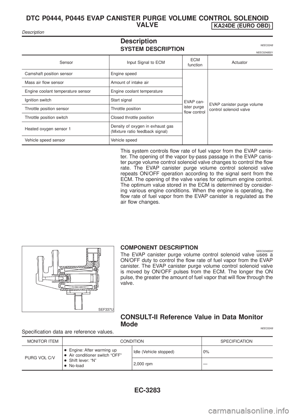
DescriptionNEEC0248SYSTEM DESCRIPTIONNEEC0248S01
Sensor Input Signal to ECMECM
functionActuator
Camshaft position sensor Engine speed
EVAP can-
ister purge
flow controlEVAP canister purge volume
control solenoid valve Mass air flow sensor Amount of intake air
Engine coolant temperature sensor Engine coolant temperature
Ignition switch Start signal
Throttle position sensor Throttle position
Throttle position switch Closed throttle position
Heated oxygen sensor 1Density of oxygen in exhaust gas
(Mixture ratio feedback signal)
Vehicle speed sensor Vehicle speed
This system controls flow rate of fuel vapor from the EVAP canis-
ter. The opening of the vapor by-pass passage in the EVAP canis-
ter purge volume control solenoid valve changes to control the flow
rate. The EVAP canister purge volume control solenoid valve
repeats ON/OFF operation according to the signal sent from the
ECM. The opening of the valve varies for optimum engine control.
The optimum value stored in the ECM is determined by consider-
ing various engine conditions. When the engine is operating, the
flow rate of fuel vapor from the EVAP canister is regulated as the
air flow changes.
SEF337U
COMPONENT DESCRIPTIONNEEC0248S02The EVAP canister purge volume control solenoid valve uses a
ON/OFF duty to control the flow rate of fuel vapor from the EVAP
canister. The EVAP canister purge volume control solenoid valve
is moved by ON/OFF pulses from the ECM. The longer the ON
pulse, the greater the amount of fuel vapor that will flow through the
valve.
CONSULT-II Reference Value in Data Monitor
Mode
NEEC0249Specification data are reference values.
MONITOR ITEM CONDITION SPECIFICATION
PURG VOL C/V+Engine: After warming up
+Air conditioner switch ªOFFº
+Shift lever: ªNº
+No-loadIdle (Vehicle stopped) 0%
2,000 rpm Ð
DTC P0444, P0445 EVAP CANISTER PURGE VOLUME CONTROL SOLENOID
VALVE
KA24DE (EURO OBD)
Description
EC-3283
Page 314 of 1306
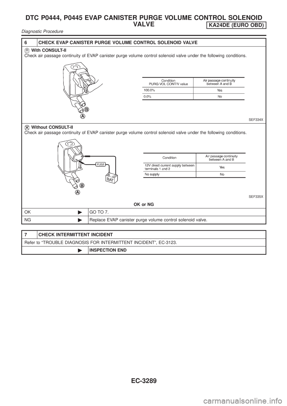
6 CHECK EVAP CANISTER PURGE VOLUME CONTROL SOLENOID VALVE
With CONSULT-II
Check air passage continuity of EVAP canister purge volume control solenoid valve under the following conditions.
SEF334X
Without CONSULT-II
Check air passage continuity of EVAP canister purge volume control solenoid valve under the following conditions.
SEF335X
OK or NG
OK©GO TO 7.
NG©Replace EVAP canister purge volume control solenoid valve.
7 CHECK INTERMITTENT INCIDENT
Refer to ªTROUBLE DIAGNOSIS FOR INTERMITTENT INCIDENTº, EC-3123.
©INSPECTION END
DTC P0444, P0445 EVAP CANISTER PURGE VOLUME CONTROL SOLENOID
VALVE
KA24DE (EURO OBD)
Diagnostic Procedure
EC-3289
Page 320 of 1306
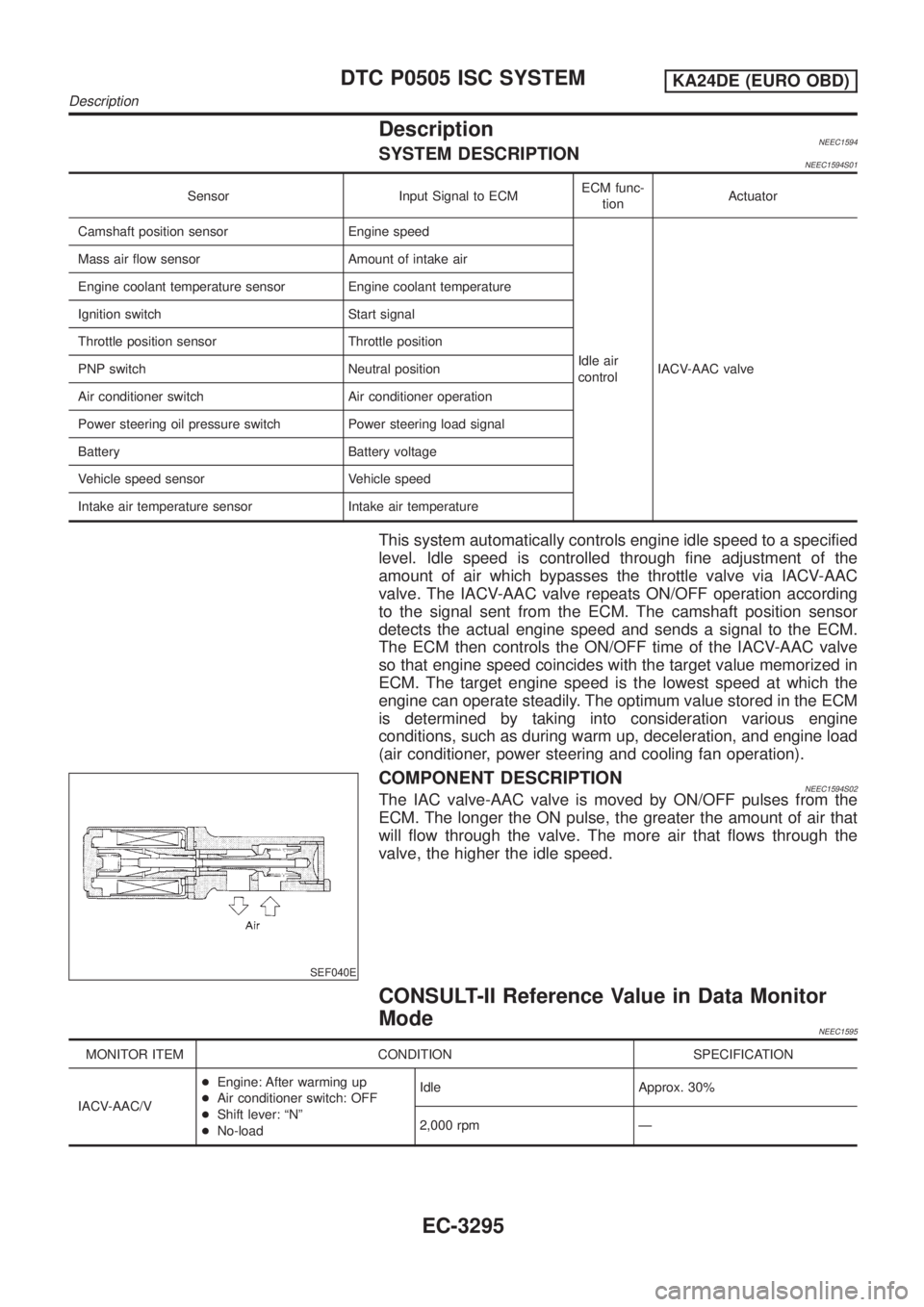
DescriptionNEEC1594SYSTEM DESCRIPTIONNEEC1594S01
Sensor Input Signal to ECMECM func-
tionActuator
Camshaft position sensor Engine speed
Idle air
controlIACV-AAC valve Mass air flow sensor Amount of intake air
Engine coolant temperature sensor Engine coolant temperature
Ignition switch Start signal
Throttle position sensor Throttle position
PNP switch Neutral position
Air conditioner switch Air conditioner operation
Power steering oil pressure switch Power steering load signal
Battery Battery voltage
Vehicle speed sensor Vehicle speed
Intake air temperature sensor Intake air temperature
This system automatically controls engine idle speed to a specified
level. Idle speed is controlled through fine adjustment of the
amount of air which bypasses the throttle valve via IACV-AAC
valve. The IACV-AAC valve repeats ON/OFF operation according
to the signal sent from the ECM. The camshaft position sensor
detects the actual engine speed and sends a signal to the ECM.
The ECM then controls the ON/OFF time of the IACV-AAC valve
so that engine speed coincides with the target value memorized in
ECM. The target engine speed is the lowest speed at which the
engine can operate steadily. The optimum value stored in the ECM
is determined by taking into consideration various engine
conditions, such as during warm up, deceleration, and engine load
(air conditioner, power steering and cooling fan operation).
SEF040E
COMPONENT DESCRIPTIONNEEC1594S02The IAC valve-AAC valve is moved by ON/OFF pulses from the
ECM. The longer the ON pulse, the greater the amount of air that
will flow through the valve. The more air that flows through the
valve, the higher the idle speed.
CONSULT-II Reference Value in Data Monitor
Mode
NEEC1595
MONITOR ITEM CONDITION SPECIFICATION
IACV-AAC/V+Engine: After warming up
+Air conditioner switch: OFF
+Shift lever: ªNº
+No-loadIdle Approx. 30%
2,000 rpm Ð
DTC P0505 ISC SYSTEMKA24DE (EURO OBD)
Description
EC-3295