2001 NISSAN PICK-UP air condition
[x] Cancel search: air conditionPage 169 of 1306
DTC No. Malfunction is detected when ... Check Items (Possible Cause)
P0101
0101B) A low voltage from the sensor is sent to ECM* under
heavy load driving condition.+Harness or connectors
(The sensor circuit is open or shorted.)
+Intake air leaks
+Mass air flow sensor
*: When this malfunction is detected, the ECM enters fail-safe mode and the MI lights up.
FAIL-SAFE MODENEEC0053S01
Detected items Engine operating condition in fail-safe mode
Mass air flow sensor circuitEngine speed will not rise more than 2,400 rpm due to the fuel
cut.
DTC Confirmation ProcedureNEEC0054CAUTION:
Always drive vehicle at a safe speed.
NOTE:
If ªDTC Confirmation Procedureº has been previously conducted,
always turn ignition switch OFF and wait at least 5 seconds before
conducting the next test.
SEF174Y
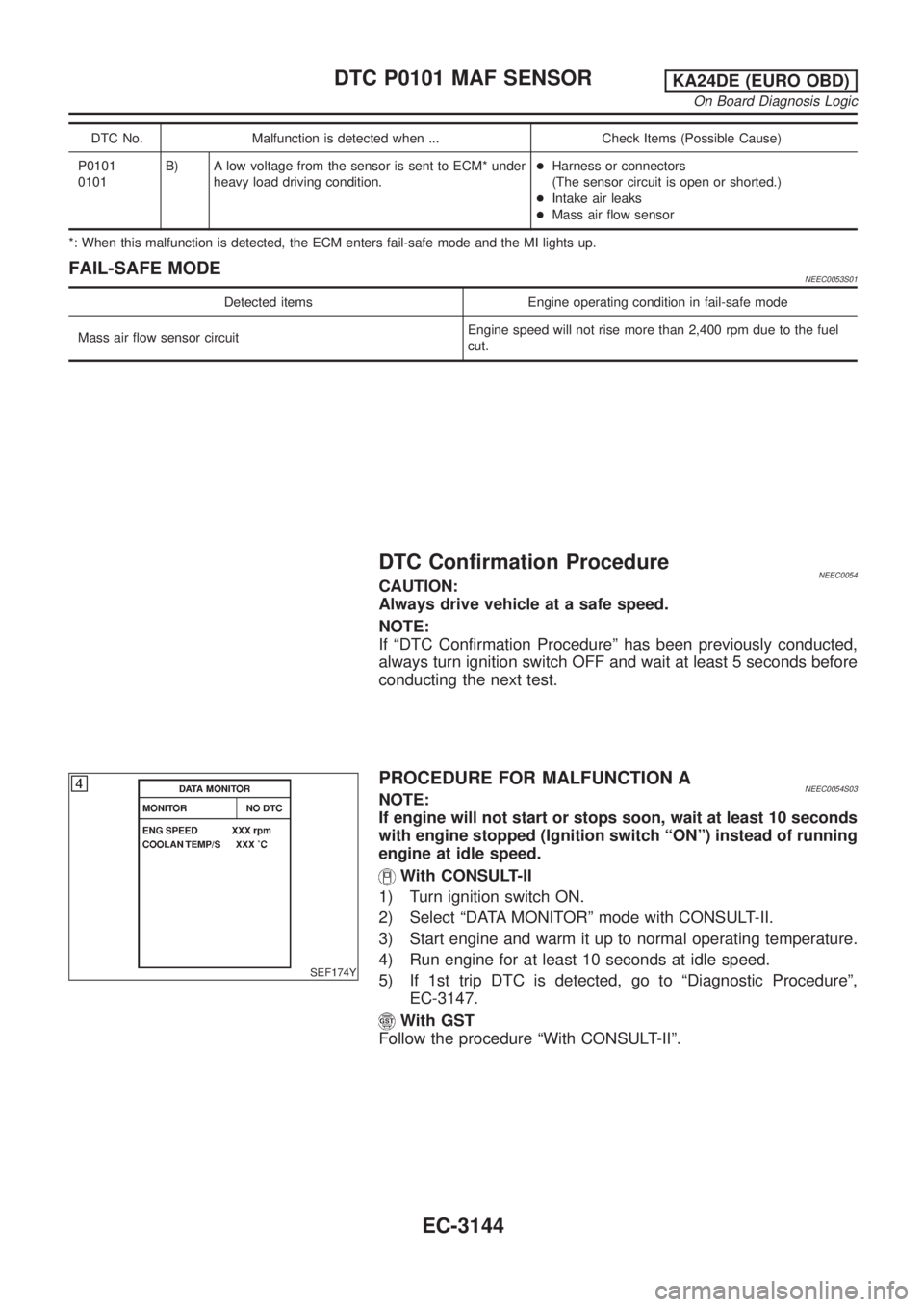
PROCEDURE FOR MALFUNCTION ANEEC0054S03NOTE:
If engine will not start or stops soon, wait at least 10 seconds
with engine stopped (Ignition switch ªONº) instead of running
engine at idle speed.
With CONSULT-II
1) Turn ignition switch ON.
2) Select ªDATA MONITORº mode with CONSULT-II.
3) Start engine and warm it up to normal operating temperature.
4) Run engine for at least 10 seconds at idle speed.
5) If 1st trip DTC is detected, go to ªDiagnostic Procedureº,
EC-3147.
With GST
Follow the procedure ªWith CONSULT-IIº.
DTC P0101 MAF SENSORKA24DE (EURO OBD)
On Board Diagnosis Logic
EC-3144
Page 170 of 1306

SEF243Y
SEF175Y
PROCEDURE FOR MALFUNCTION BNEEC0054S04With CONSULT-II
1) Turn ignition switch ON.
2) Start engine and warm it up to normal operating temperature.
If engine cannot be started, go to ªDiagnostic Procedureº,
EC-3147.
3) Select ªDATA MONITORº mode with CONSULT-II.
4) Check the voltage of ªMAS A/F SE-B1º with ªDATA MONITORº.
5) Increases engine speed to about 4,000 rpm.
6) Monitor the linear voltage rise in response to engine speed
increases.
If NG, go to ªDiagnostic Procedureº, EC-3147.
If OK, go to following step.
7) Maintain the following conditions for at least 10 consecutive
seconds.
ENG SPEED More than 2,000 rpm
THRTL POS SEN More than 3V
Selector lever Suitable position
Driving location Driving vehicle uphill (Increased engine load)
will help maintain the driving conditions
required for this test.
8) If 1st trip DTC is detected, go to ªDiagnostic Procedureº,
EC-3147.
SEF534P
Overall Function CheckNEEC0055Use this procedure to check the overall function of the mass air flow
sensor circuit. During this check, a 1st trip DTC might not be con-
firmed.
PROCEDURE FOR MALFUNCTION BNEEC0055S01With GST
1) Turn ignition switch ON.
2) Start engine and warm it up to normal operating temperature.
3) Select ªMODE 1º with GST.
4) Check the mass air flow sensor signal with ªMODE 1º.
5) Check for linear mass air flow rise in response to increases to
about 4,000 rpm in engine speed.
6) If NG, go to ªDiagnostic Procedureº, EC-3147.
DTC P0101 MAF SENSORKA24DE (EURO OBD)
DTC Confirmation Procedure
EC-3145
Page 176 of 1306
SEF893J
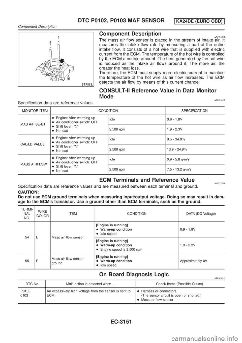
Component DescriptionNEEC1548The mass air flow sensor is placed in the stream of intake air. It
measures the intake flow rate by measuring a part of the entire
intake flow. It consists of a hot wire that is supplied with electric
current from the ECM. The temperature of the hot wire is controlled
by the ECM a certain amount. The heat generated by the hot wire
is reduced as the intake air flows around it. The more air, the
greater the heat loss.
Therefore, the ECM must supply more electric current to maintain
the temperature of the hot wire as air flow increases. The ECM
detects the air flow by means of this current change.
CONSULT-II Reference Value in Data Monitor
Mode
NEEC1549Specification data are reference values.
MONITOR ITEM CONDITION SPECIFICATION
MAS A/F SE-B1+Engine: After warming up
+Air conditioner switch: OFF
+Shift lever: ªNº
+No-loadIdle 0.9 - 1.8V
2,500 rpm 1.9 - 2.3V
CAL/LD VALUE+Engine: After warming up
+Air conditioner switch: OFF
+Shift lever: ªNº
+No-loadIdle 9.5 - 34.0%
2,500 rpm 13.9 - 24.9%
MASS AIRFLOW+Engine: After warming up
+Air conditioner switch: OFF
+Shift lever: ªNº
+No-loadIdle 0.9 - 5.8 g´m/s
2,500 rpm 7.5 - 13.2 g´m/s
ECM Terminals and Reference ValueNEEC1550Specification data are reference values and are measured between each terminal and ground.
CAUTION:
Do not use ECM ground terminals when measuring input/output voltage. Doing so may result in dam-
age to the ECM's transistor. Use a ground other than ECM terminals, such as the ground.
TERMI-
NAL
NO.WIRE
COLORITEM CONDITION DATA (DC Voltage)
54 L Mass air flow sensor[Engine is running]
+Warm-up condition
+Idle speed0.9 - 1.8V
[Engine is running]
+Warm-up condition
+Engine speed is 2,500 rpm1.9 - 2.3V
55 PMass air flow sensor
ground[Engine is running]
+Warm-up condition
+Idle speedApproximately 0V
On Board Diagnosis LogicNEEC1551
DTC No. Malfunction is detected when ... Check Items (Possible Cause)
P0103
0103An excessively high voltage from the sensor is sent to
ECM.+Harness or connectors
(The sensor circuit is open or shorted.)
+Mass air flow sensor
DTC P0102, P0103 MAF SENSORKA24DE (EURO OBD)
Component Description
EC-3151
Page 177 of 1306
DTC No. Malfunction is detected when ... Check Items (Possible Cause)
P0102
0102An excessively low voltage from the sensor is sent to
ECM* when engine is running.+Harness or connectors
(The sensor circuit is open or shorted.)
+Intake air leaks
+Mass air flow sensor
*: When this malfunction is detected, the ECM enters fail-safe mode and the MI lights up.
FAIL-SAFE MODENEEC1551S01
Detected items Engine operating condition in fail-safe mode
Mass air flow sensor circuitEngine speed will not rise more than 2,400 rpm due to the fuel
cut.
DTC Confirmation ProcedureNEEC1552CAUTION:
Always drive vehicle at a safe speed.
NOTE:
If ªDTC Confirmation Procedureº has been previously conducted,
always turn ignition switch OFF and wait at least 5 seconds before
conducting the next test.
SEF058Y
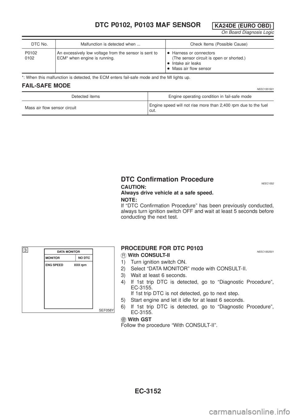
PROCEDURE FOR DTC P0103NEEC1552S01With CONSULT-II
1) Turn ignition switch ON.
2) Select ªDATA MONITORº mode with CONSULT-II.
3) Wait at least 6 seconds.
4) If 1st trip DTC is detected, go to ªDiagnostic Procedureº,
EC-3155.
If 1st trip DTC is not detected, go to next step.
5) Start engine and let it idle for at least 6 seconds.
6) If 1st trip DTC is detected, go to ªDiagnostic Procedureº,
EC-3155.
With GST
Follow the procedure ªWith CONSULT-IIº.
DTC P0102, P0103 MAF SENSORKA24DE (EURO OBD)
On Board Diagnosis Logic
EC-3152
Page 185 of 1306
SEF329V
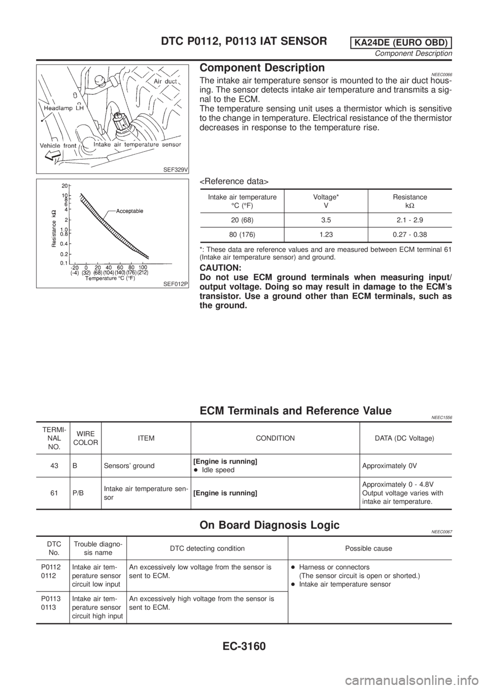
Component DescriptionNEEC0066The intake air temperature sensor is mounted to the air duct hous-
ing. The sensor detects intake air temperature and transmits a sig-
nal to the ECM.
The temperature sensing unit uses a thermistor which is sensitive
to the change in temperature. Electrical resistance of the thermistor
decreases in response to the temperature rise.
SEF012P
Intake air temperature
ÉC (ÉF)Voltage*
VResistance
kW
20 (68) 3.5 2.1 - 2.9
80 (176) 1.23 0.27 - 0.38
*: These data are reference values and are measured between ECM terminal 61
(Intake air temperature sensor) and ground.
CAUTION:
Do not use ECM ground terminals when measuring input/
output voltage. Doing so may result in damage to the ECM's
transistor. Use a ground other than ECM terminals, such as
the ground.
ECM Terminals and Reference ValueNEEC1556
TERMI-
NAL
NO.WIRE
COLORITEM CONDITION DATA (DC Voltage)
43 B Sensors' ground[Engine is running]
+Idle speedApproximately 0V
61 P/BIntake air temperature sen-
sor[Engine is running]Approximately 0 - 4.8V
Output voltage varies with
intake air temperature.
On Board Diagnosis LogicNEEC0067
DTC
No.Trouble diagno-
sis nameDTC detecting condition Possible cause
P0112
0112Intake air tem-
perature sensor
circuit low inputAn excessively low voltage from the sensor is
sent to ECM.+Harness or connectors
(The sensor circuit is open or shorted.)
+Intake air temperature sensor
P0113
0113Intake air tem-
perature sensor
circuit high inputAn excessively high voltage from the sensor is
sent to ECM.
DTC P0112, P0113 IAT SENSORKA24DE (EURO OBD)
Component Description
EC-3160
Page 186 of 1306
FAIL-SAFE MODENEEC0067S01When the malfunction is detected, the ECM enters fail-safe mode and the MI lights up.
Engine operating condition in fail-safe mode
The ECM functions on the assumption that the intake air temperature is 25ÉC (77ÉF).
DTC Confirmation ProcedureNEEC0068NOTE:
If ªDTC Confirmation Procedureº has been previously conducted,
always turn ignition switch OFF and wait at least 5 seconds before
conducting the next test.
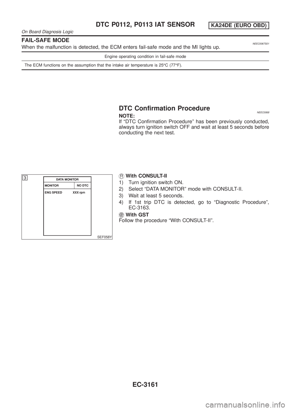
SEF058Y
With CONSULT-II
1) Turn ignition switch ON.
2) Select ªDATA MONITORº mode with CONSULT-II.
3) Wait at least 5 seconds.
4) If 1st trip DTC is detected, go to ªDiagnostic Procedureº,
EC-3163.
With GST
Follow the procedure ªWith CONSULT-IIº.
DTC P0112, P0113 IAT SENSORKA24DE (EURO OBD)
On Board Diagnosis Logic
EC-3161
Page 196 of 1306
ECM Terminals and Reference Value=NEEC0081Specification data are reference values and are measured between each terminal and ground.
CAUTION:
Do not use ECM ground terminals when measuring input/output voltage. Doing so may result in dam-
age to the ECM's transistor. Use a ground other than ECM terminals, such as the ground.
TERMI-
NAL
NO.WIRE
COLORITEM CONDITION DATA (DC Voltage)
23 G Throttle position sensor[Ignition switch ON]
+Warm-up condition
+Accelerator pedal fully released0.2 - 0.8V
[Ignition switch ON]
+Accelerator pedal fully depressed3.5 - 4.5V
42 G/B Sensors' power supply[Ignition switch ON]Approximately 5V
43 B Sensors' ground[Engine is running]
+Idle speedApproximately 0V
On Board Diagnosis LogicNEEC0082
DTC No. Malfunction is detected when ... Check Items (Possible Cause)
P0121
0121A) A high voltage from the sensor is sent to ECM
under light load driving condition.+Harness or connectors
(The throttle position sensor circuit is open or
shorted.)
+Throttle position sensor
+Fuel injector
+Camshaft position sensor
+Mass air flow sensor
B) A low voltage from the sensor is sent to ECM under
heavy load driving condition.+Harness or connectors
(The throttle position sensor circuit is open or
shorted.)
+Intake air leaks
+Throttle position sensor
DTC P0121 TP SENSORKA24DE (EURO OBD)
ECM Terminals and Reference Value
EC-3171
Page 202 of 1306
7 DETECT MALFUNCTIONING PART
Check harness for open or short between ECM and throttle position sensor.
©Repair open circuit or short to power in harness or connectors.
8 CHECK INPUT SIGNAL CIRCUIT
1. Disconnect ECM harness connector.
2. Check harness continuity between ECM terminal 23 and terminal 2.
Refer to the Wiring Diagram.
Continuity should exist.
3. Also check harness for short to ground and short to power.
OK or NG
OK (With CONSULT-II)©GO TO 9.
OK (Without CONSULT-
II)©GO TO 10.
NG©Repair open circuit or short to ground or short to power in harness or connectors.
9 CHECK THROTTLE POSITION SENSOR
With CONSULT-II
1. Reconnect all harness connectors disconnected.
2. Start engine and warm it up to normal operating temperature.
3. Stop engine and turn ignition switch ON.
4. Select ªDATA MONITORº mode with CONSULT-II.
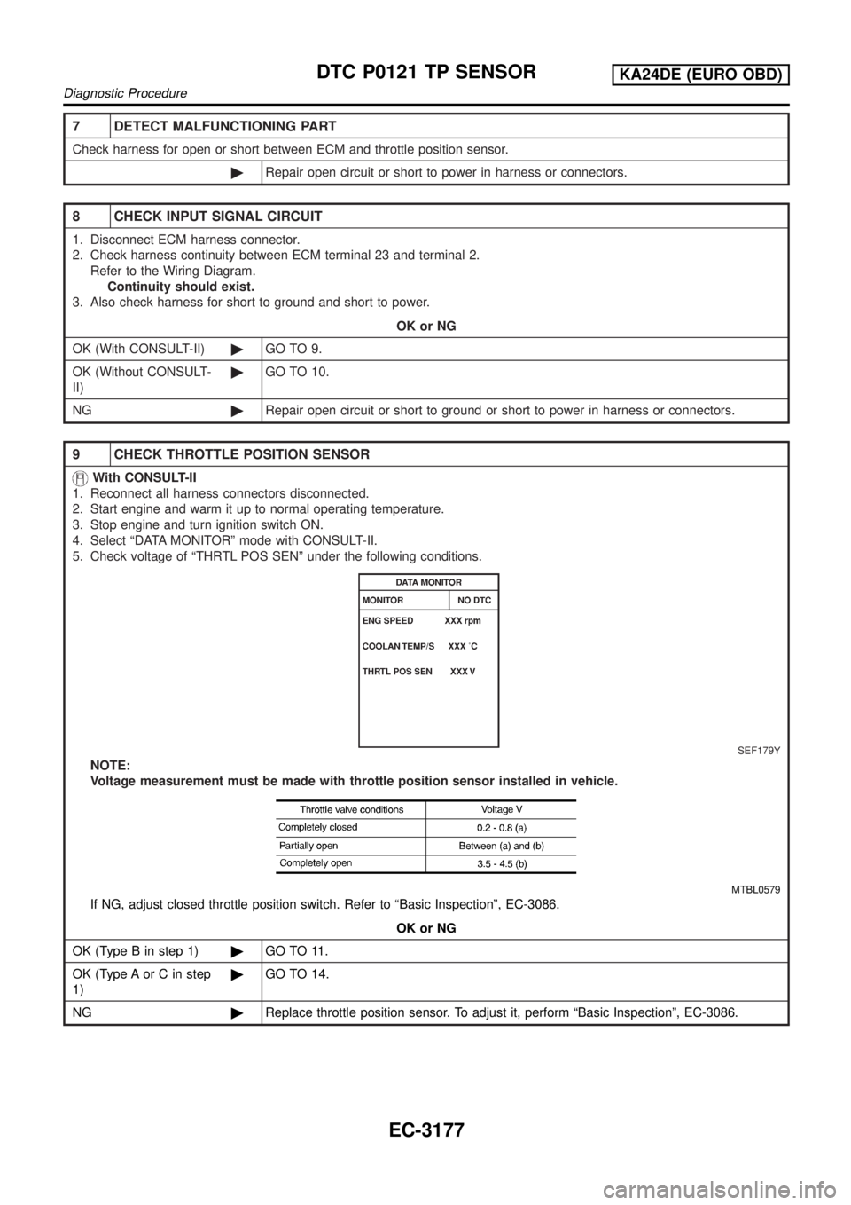
5. Check voltage of ªTHRTL POS SENº under the following conditions.
SEF179Y
NOTE:
Voltage measurement must be made with throttle position sensor installed in vehicle.
MTBL0579
If NG, adjust closed throttle position switch. Refer to ªBasic Inspectionº, EC-3086.
OK or NG
OK (Type B in step 1)©GO TO 11.
OK (Type A or C in step
1)©GO TO 14.
NG©Replace throttle position sensor. To adjust it, perform ªBasic Inspectionº, EC-3086.
DTC P0121 TP SENSORKA24DE (EURO OBD)
Diagnostic Procedure
EC-3177