2001 NISSAN PICK-UP AUX
[x] Cancel search: AUXPage 945 of 1306

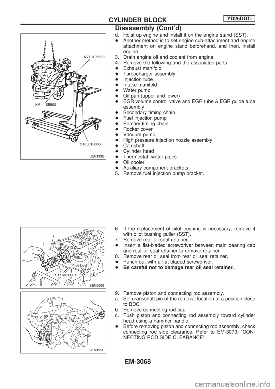
d. Hoist up engine and install it on the engine stand (SST).
+Another method is to set engine sub-attachment and engine
attachment on engine stand beforehand, and then, install
engine.
3. Drain engine oil and coolant from engine.
4. Remove the following and the associated parts:
+Exhaust manifold
+Turbocharger assembly
+Injection tube
+Intake manifold
+Water pump
+Oil pan (upper and lower)
+EGR volume control valve and EGR tube & EGR guide tube
assembly
+Secondary timing chain
+Fuel injection pump
+Primary timing chain
+Rocker cover
+Vacuum pump
+High pressure injection nozzle assembly
+Camshaft
+Cylinder head
+Thermostat, water pipes
+Oil cooler
+Auxiliary component brackets
5. Remove fuel injection pump bracket.
6. If the replacement of pilot bushing is necessary, remove it
with pilot bushing puller (SST).
7. Remove rear oil seal retainer.
+Insert a flat-bladed screwdriver between main bearing cap
and rear oil seal retainer to remove retainer.
8. Remove rear oil seal from rear oil seal retainer.
+Punch out with a flat-bladed screwdriver.
+Be careful not to damage rear oil seal retainer.
9. Remove piston and connecting rod assembly.
a. Set crankshaft pin of the removal location at a position close
to BDC.
b. Remove connecting rod cap.
c. Push piston and connecting rod assembly toward cylinder
head using a hammer handle.
+Before removing piston and connecting rod assembly, check
connecting rod side clearance. Refer to EM-3070, ªCON-
NECTING ROD SIDE CLEARANCEº.
JEM193G
SEM500G
JEM195G
CYLINDER BLOCKYD25DDTi
Disassembly (Cont'd)
EM-3068
Page 961 of 1306

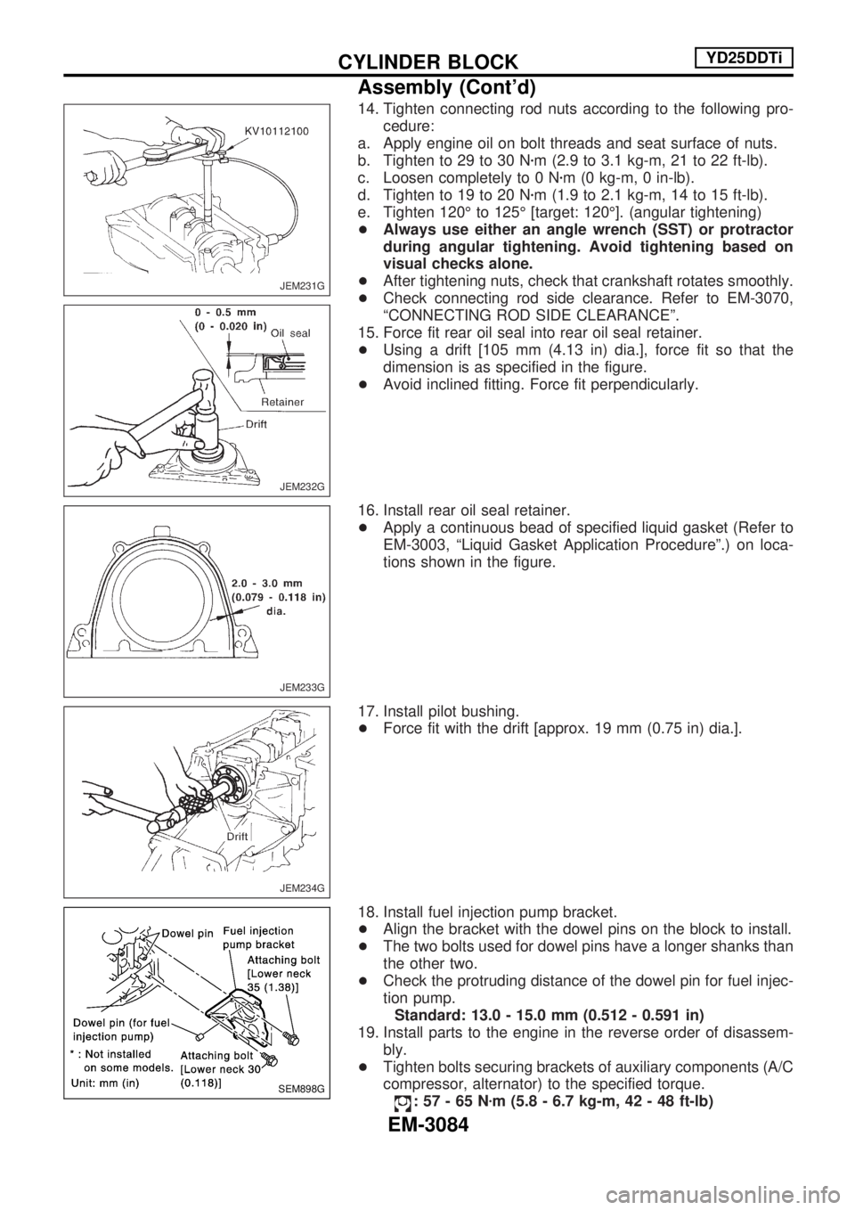
14. Tighten connecting rod nuts according to the following pro-
cedure:
a. Apply engine oil on bolt threads and seat surface of nuts.
b. Tighten to 29 to 30 Nzm (2.9 to 3.1 kg-m, 21 to 22 ft-lb).
c. Loosen completely to 0 Nzm (0 kg-m, 0 in-lb).
d. Tighten to 19 to 20 Nzm (1.9 to 2.1 kg-m, 14 to 15 ft-lb).
e. Tighten 120É to 125É [target: 120É]. (angular tightening)
+Always use either an angle wrench (SST) or protractor
during angular tightening. Avoid tightening based on
visual checks alone.
+After tightening nuts, check that crankshaft rotates smoothly.
+Check connecting rod side clearance. Refer to EM-3070,
ªCONNECTING ROD SIDE CLEARANCEº.
15. Force fit rear oil seal into rear oil seal retainer.
+Using a drift [105 mm (4.13 in) dia.], force fit so that the
dimension is as specified in the figure.
+Avoid inclined fitting. Force fit perpendicularly.
16. Install rear oil seal retainer.
+Apply a continuous bead of specified liquid gasket (Refer to
EM-3003, ªLiquid Gasket Application Procedureº.) on loca-
tions shown in the figure.
17. Install pilot bushing.
+Force fit with the drift [approx. 19 mm (0.75 in) dia.].
18. Install fuel injection pump bracket.
+Align the bracket with the dowel pins on the block to install.
+The two bolts used for dowel pins have a longer shanks than
the other two.
+Check the protruding distance of the dowel pin for fuel injec-
tion pump.
Standard: 13.0 - 15.0 mm (0.512 - 0.591 in)
19. Install parts to the engine in the reverse order of disassem-
bly.
+Tighten bolts securing brackets of auxiliary components (A/C
compressor, alternator) to the specified torque.
:57-65Nzm (5.8 - 6.7 kg-m, 42 - 48 ft-lb)
JEM231G
JEM232G
JEM233G
JEM234G
SEM898G
CYLINDER BLOCKYD25DDTi
Assembly (Cont'd)
EM-3084
Page 1062 of 1306

A
A/C relay ..................................... HA-3019, 3029
A/C trouble diagnoses (auto A/C) ......... HA-3020
A/C trouble diagnoses
(manual A/C) ........................... HA-3004, 3020
A/C, A - Wiring diagram ........................ HA-3021
A/C, M - Wiring diagram ............. HA-3006, 3009
A/T IND - Wiring diagram ...................... EL-3100
AAC/V - Wiring diagram ....................... EC-3298
ABS - Wiring diagram ................. BR-3003, 3010
AT indicator lamp .................................. EL-3100
Accelerator control system .................... FE-3002
Accelerator position sensor ........ EC-3515, 3516
Air bag disposal .................................... RS-3011
Air bag ................................................... RS-3003
Air cleaner filter replacement ..... MA-3010, 3019
Air conditioner cut control . EC-3028, 3413, 3414
Air flow meter - See Mass air flow
sensor ................................................ EC-3151
Alternator ............................................... EL-3022
Angular tightening application .............. EM-3003
Antenna ................................................. EL-3115
Anti-lock brake system - Wiring
diagram ......................... BR-3002, 3003, 3009
Auxiliary air control (AAC) valve ........... EC-3295
B
BACK/L - Wiring diagram ...................... EL-3044
BOOST - Wiring diagram ....................................
Back-up lamp ......................................... EL-3044
Basic inspection ................ EC-3086, 3444, 3445
Battery ................................................... EL-3013
Bumper, front ....................................... BT-3002
C
CHARGE - Wiring diagram ................... EL-3018
CIGAR - Wiring diagram ....................... EL-3110
CKPS - Wiring diagram .............. EC-3266, 3351
CLOCK - Wiring diagram ...................... EL-3111
CMPS - Wiring diagram ........................ EC-3273
CONSULT for engine ....... EC-3070, 3434, 3435
Camshaft inspection ............................. EM-3050
Camshaft position sensor (CMPS) ....... EC-3270
Canister - See EVAP canister .............. EC-3029
Center case (Transfer) .......................... TF-3003
Charging system .................................... EL-3018
Cigarette lighter ..................................... EL-3110
Clock ...................................................... EL-3111
Closed throttle position switch ............. EC-3301
Collision diagnosis ................................ RS-3037
Combination lamp, front, removal and
installation .......................................... BT-3002
Combination meter ................................ EL-3056
Compression pressure ......................... EM-3013
Connecting rod bearing clearance ....... EM-3077Connecting rod bushing clearance ....... EM-3080
Connecting rod ..................................... EM-3072
Coolant replacement ............................ MA-3014
Cooling circuit (engine) ......................... LC-3010
Cooling fan control system ......... LC-3002, 3017
Cooling fan control ........... EC-3344, 3489, 3490
Cooling fan ............................................ LC-3016
Counter gear (Transfer) ......................... TF-3004
Crank angle sensor built into
distributor - See Camshaft position
sensor ................................................ EC-3270
Crankcase emission control system -
See Positive crankcase
ventilation ...................... EC-3032, 3414, 3415
Crankcase ventilation system - See
Positive crankcase
ventilation ...................... EC-3032, 3414, 3415
Crankshaft position sensor (OBD) cog
chipping ............................................. EC-3349
Crankshaft position sensor (OBD) ........ EC-3264
Crankshaft position sensor
(TDC) ...................................... EC-3534, 3535
Crankshaft ............................................ EM-3075
Cylinder block ....................................... EM-3066
Cylinder head ....................................... EM-3046
D
DEF - Wiring diagram ............................ EL-3112
DIMDIP - Wiring diagram ...................... EL-3033
DTC P0121 TP Sensor ........................ EC-3170
DTC work support ................................. EC-3078
DTRL - Wiring diagram ......................... EL-3029
Data link connector for
Consult .......................... EC-3033, 3434, 3435
Daytime light system ............................. EL-3029
Detonation sensor - See Knock
sensor ................................................ EC-3260
Diagnosis sensor unit ........................... RS-3005
Diagnostic trouble code (DTC) for
OBD system .................. EC-3009, 3428, 3429
Diagnostic trouble code (DTC) inspec-
tion priority chart ............................... EC-3100
Dim-dip lamp system ............................. EL-3033
Distributor ignition (DI) system ............. EC-3026
Distributor .............................................. EC-3026
Drive belt inspection ............................. MA-3011
Drive chain (Transfer) ............................ TF-3004
E
ECCS-D control
module ......... EC-3595, 3594, 3598, 3599, 3463,
3464, 3501, 3502, 3581, 3582,
3583, 3584, 3585, 3586
ECM input/output signal ... EC-3110, 3463, 3464
ECTS - Wiring diagram ......................... EC-3167
EGR - Wiring diagram ................ EC-3607, 3608
ALPHABETICAL INDEX
IDX-3002