2001 NISSAN PICK-UP immobilizer
[x] Cancel search: immobilizerPage 26 of 1306

ENGINE CONTROL SYSTEM
SECTION
EC
CONTENTS
PRECAUTIONS AND PREPARATION............... 3008
Special Service Tool (YD25DDTi) ................... 3008
Supplemental Restraint System (SRS)²AIR
BAG²................................................................ 3008
KA24DE (EURO OBD)
Trouble Diagnosis - Index................................. 3009
Alphabetical & P No. Index for DTC................ 3009
Precautions......................................................... 3012
Supplemental Restraint System (SRS)²AIR
BAG²and²SEAT BELT PRE-TENSIONER².. 3012
Precautions for On Board Diagnostic (OBD)
System of Engine............................................. 3012
Engine Fuel & Emission Control System ........ 3013
Precautions ...................................................... 3014
Wiring Diagrams and Trouble Diagnosis ......... 3015
Preparation.......................................................... 3016
Special Service Tools ...................................... 3016
Commercial Service Tools ............................... 3016
Engine and Emission Control Overall System3018
Engine Control Component Parts Location ..... 3018
Circuit Diagram ................................................ 3020
System Diagram .............................................. 3021
Vacuum Hose Drawing .................................... 3022
System Chart ................................................... 3023
Engine and Emission Basic Control System
Description.......................................................... 3024
Multiport Fuel Injection (MFI) System.............. 3024
Distributor Ignition (DI) System........................ 3026
Air Conditioning Cut Control ............................ 3028
Fuel Cut Control (at no load & high engine
speed) .............................................................. 3028Evaporative Emission System ......................... 3029
Positive Crankcase Ventilation ........................ 3032
Basic Service Procedure................................... 3033
Fuel Pressure Release .................................... 3033
Fuel Pressure Check ....................................... 3033
Fuel Pressure Regulator Check ...................... 3034
Injector ............................................................. 3034
Fast Idle Cam (FIC) ......................................... 3035
Idle Speed/Ignition Timing/Idle Mixture Ratio
Adjustment ....................................................... 3035
On Board Diagnostic System Description...... 3049
Introduction ...................................................... 3049
Two Trip Detection Logic ................................. 3049
Emission-related Diagnostic Information ......... 3049
NVIS (Nissan Vehicle Immobilizer System -
NATS) .............................................................. 3061
Malfunction Indicator (MI) ................................ 3061
OBD System Operation Chart ......................... 3064
CONSULT-II ..................................................... 3070
Generic Scan Tool (GST) ................................ 3080
Trouble Diagnosis - Introduction..................... 3082
Introduction ...................................................... 3082
Work Flow ........................................................ 3084
Trouble Diagnosis - Basic Inspection.............. 3086
Basic Inspection ............................................... 3086
Trouble Diagnosis - General Description........ 3100
DTC Inspection Priority Chart .......................... 3100
Fail-safe Chart ................................................. 3101
Symptom Matrix Chart ..................................... 3102
CONSULT-II Reference Value in Data Monitor
Mode ................................................................ 3106
Major Sensor Reference Graph in Data
Monitor Mode ................................................... 3107
BR
Page 86 of 1306
Actual work procedures are explained using a DTC as an example. Be careful so that not only the DTC, but
all of the data listed above, are cleared from the ECM memory during work procedures.
NVIS (Nissan Vehicle Immobilizer System Ð
NATS)
NEEC1601
SEF515Y
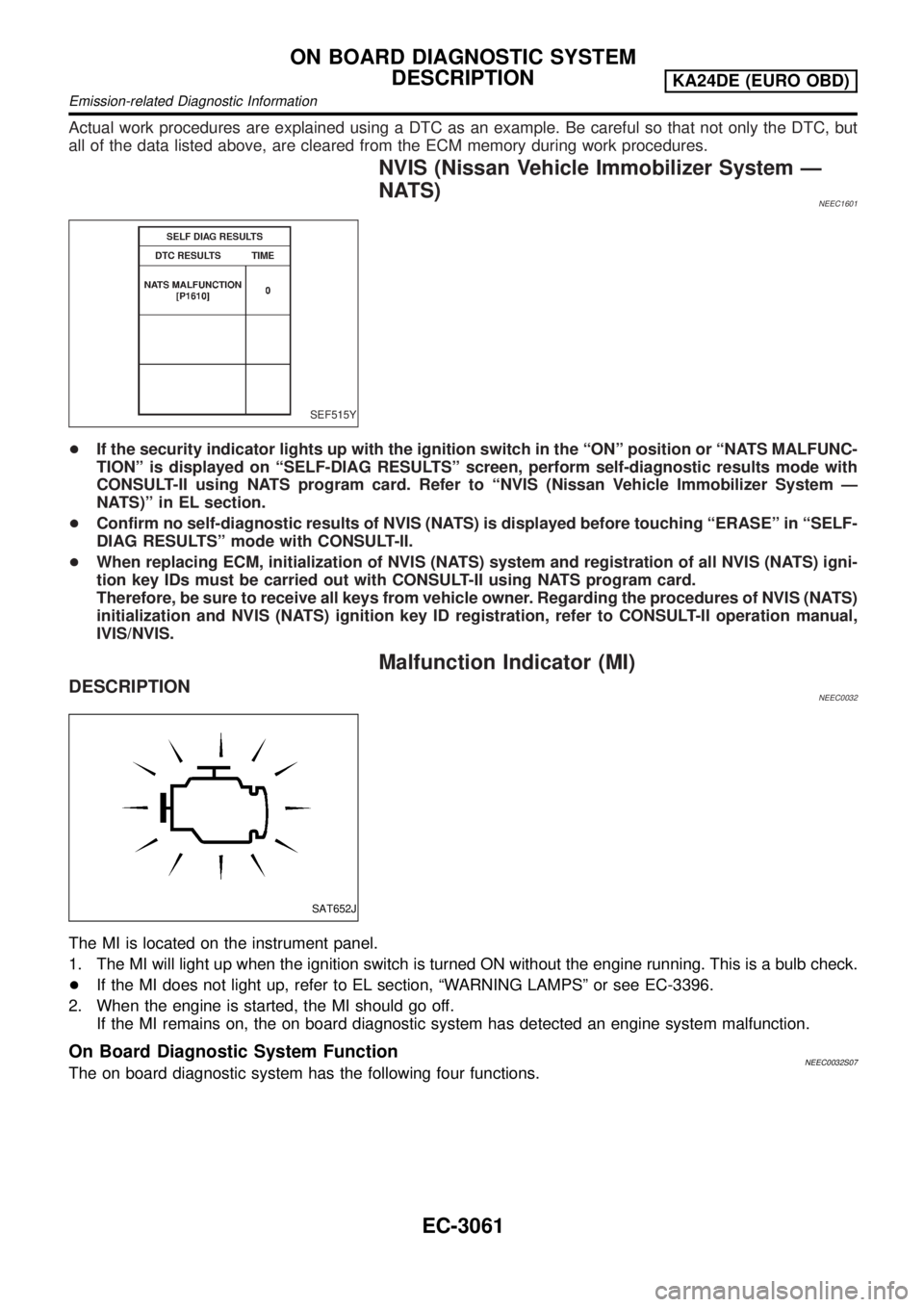
+If the security indicator lights up with the ignition switch in the ªONº position or ªNATS MALFUNC-
TIONº is displayed on ªSELF-DIAG RESULTSº screen, perform self-diagnostic results mode with
CONSULT-II using NATS program card. Refer to ªNVIS (Nissan Vehicle Immobilizer System Ð
NATS)º in EL section.
+Confirm no self-diagnostic results of NVIS (NATS) is displayed before touching ªERASEº in ªSELF-
DIAG RESULTSº mode with CONSULT-II.
+When replacing ECM, initialization of NVIS (NATS) system and registration of all NVIS (NATS) igni-
tion key IDs must be carried out with CONSULT-II using NATS program card.
Therefore, be sure to receive all keys from vehicle owner. Regarding the procedures of NVIS (NATS)
initialization and NVIS (NATS) ignition key ID registration, refer to CONSULT-II operation manual,
IVIS/NVIS.
Malfunction Indicator (MI)
DESCRIPTIONNEEC0032
SAT652J
The MI is located on the instrument panel.
1. The MI will light up when the ignition switch is turned ON without the engine running. This is a bulb check.
+If the MI does not light up, refer to EL section, ªWARNING LAMPSº or see EC-3396.
2. When the engine is started, the MI should go off.
If the MI remains on, the on board diagnostic system has detected an engine system malfunction.
On Board Diagnostic System FunctionNEEC0032S07The on board diagnostic system has the following four functions.
ON BOARD DIAGNOSTIC SYSTEM
DESCRIPTION
KA24DE (EURO OBD)
Emission-related Diagnostic Information
EC-3061
Page 334 of 1306
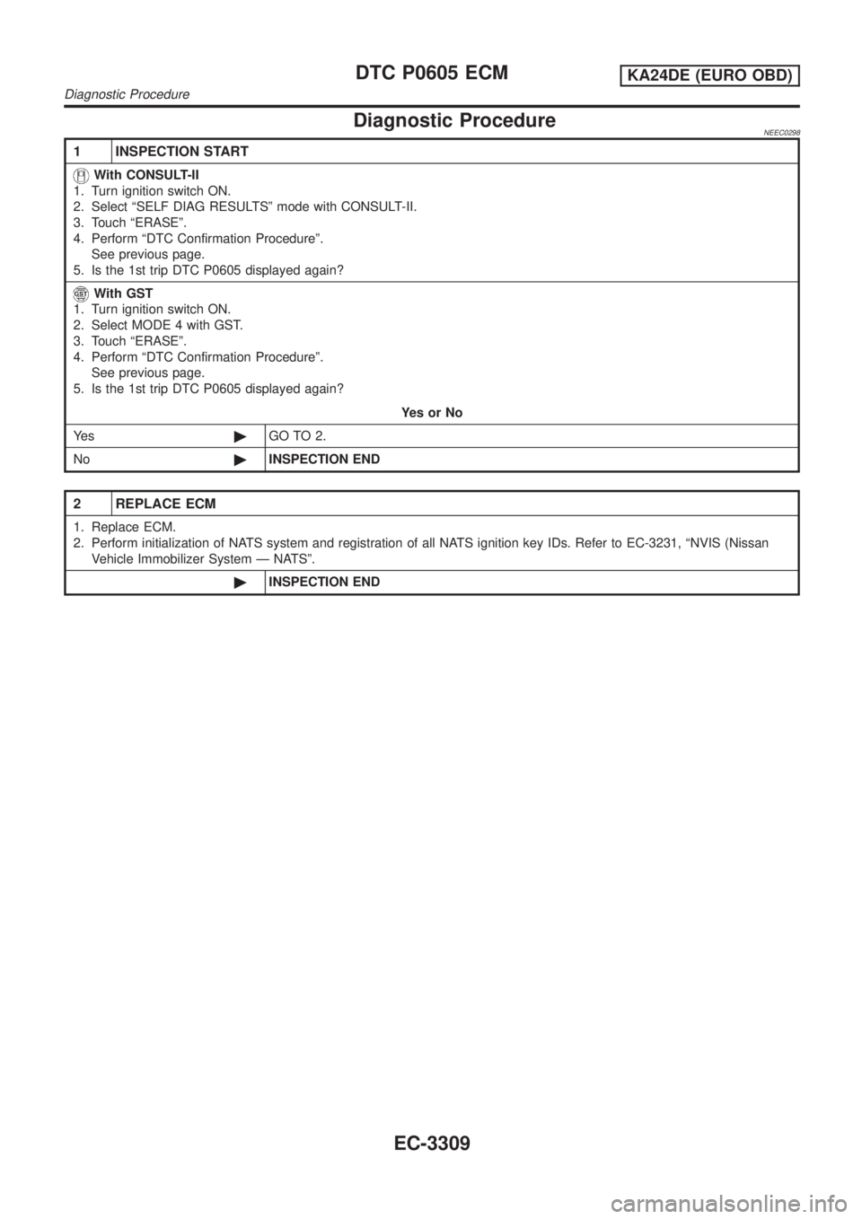
Diagnostic ProcedureNEEC0298
1 INSPECTION START
With CONSULT-II
1. Turn ignition switch ON.
2. Select ªSELF DIAG RESULTSº mode with CONSULT-II.
3. Touch ªERASEº.
4. Perform ªDTC Confirmation Procedureº.
See previous page.
5. Is the 1st trip DTC P0605 displayed again?
With GST
1. Turn ignition switch ON.
2. Select MODE 4 with GST.
3. Touch ªERASEº.
4. Perform ªDTC Confirmation Procedureº.
See previous page.
5. Is the 1st trip DTC P0605 displayed again?
YesorNo
Ye s©GO TO 2.
No©INSPECTION END
2 REPLACE ECM
1. Replace ECM.
2. Perform initialization of NATS system and registration of all NATS ignition key IDs. Refer to EC-3231, ªNVIS (Nissan
Vehicle Immobilizer System Ð NATSº.
©INSPECTION END
DTC P0605 ECMKA24DE (EURO OBD)
Diagnostic Procedure
EC-3309
Page 814 of 1306
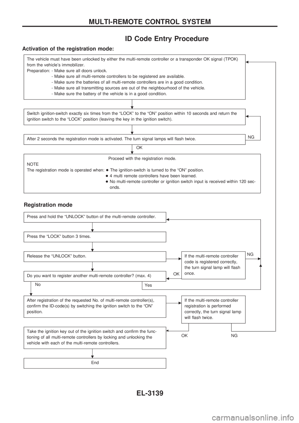
ID Code Entry Procedure
Activation of the registration mode:
The vehicle must have been unlocked by either the multi-remote controller or a transponder OK signal (TPOK)
from the vehicle's immobilizer.
Preparation: - Make sure all doors unlock.
- Make sure all multi-remote controllers to be registered are available.
- Make sure the batteries of all multi-remote controllers are in a good condition.
- Make sure all transmitting sources are out of the neighbourhood of the vehicle.
- Make sure the battery of the vehicle is in a good condition.b
Switch ignition-switch exactly six times from the ªLOCKº to the ªONº position within 10 seconds and return the
ignition switch to the ªLOCKº position (leaving the key in the ignition switch).b
After 2 seconds the registration mode is activated. The turn signal lamps will flash twice.
OKNG
Proceed with the registration mode.
NOTE
The registration mode is operated when:+The ignition-switch is turned to the ªONº position.
+4 multi remote controllers have been learned.
+No multi-remote controller or ignition switch input is received within 120 sec-
onds.
Registration mode
Press and hold the ªUNLOCKº button of the multi-remote controller.b
Press the ªLOCKº button 3 times.
Release the ªUNLOCKº button.cIf the multi-remote controller
code is registered correctly,
the turn signal lamp will flash
once.cNG
Do you want to register another multi-remote controller? (max. 4)
No
Yes
bOK
m
After registration of the requested No. of multi-remote controller(s),
confirm the ID-code(s) by switching the ignition switch to the ªONº
position.cIf the multi-remote controller
registration is performed
correctly, the turn signal lamp
will flash twice.
Take the ignition key out of the ignition switch and confirm the func-
tioning of all multi-remote controllers by locking and unlocking the
vehicle with each of the multi-remote controllers.b
OKNG
End
.
.
.
.
.
.
.
.
MULTI-REMOTE CONTROL SYSTEM
EL-3139
Page 818 of 1306
System Description
NATS has the following immobilizer functions:
+Since only NATS ignition keys, whose ID nos. have been registered into the ECM and IMMU of NATS,
allow the engine to run, operation of a stolen vehicle without a NATS registered key is prevented by
NATS.
That is to say, NATS will immobilize the engine if someone tries to start it without the registered key of
NATS.
+This version of NATS has dongle unit to improve its anti-theft performance (RHD models for Europe).
Dongle unit has its own ID which is registered into NATS IMMU. So it dongle unit is replaced, initializa-
tion must be carried out.
+When malfunction of dongle unit is detected:
Ð The security indicator lamp illuminates for about 15 minutes after ignition switch is turned to ON.
Ð When dongle unit has a malfunction and the indicator lamp is illuminated, engine can not be started.
However, engine can be started only one time when security indicator turns off in about 15 minutes
after ignition switch is turned to ON.
+Both of the originally supplied ignition key IDs have been NATS registered.
If requested by the vehicle owner, a maximum of five key IDs can be registered into the NATS compo-
nents.
+The NATS security indicator (NATS security ind.) blinks when the ignition switch is in ªOFFº or ªACCº
position. Therefore, NATS warns outsiders that the vehicle is equipped with the anti-theft system.
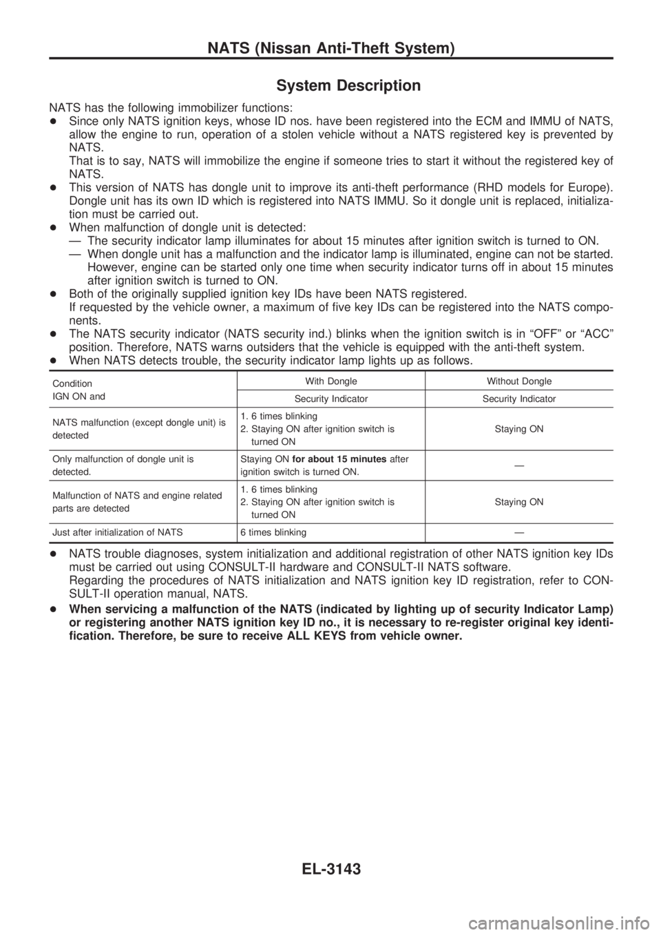
+When NATS detects trouble, the security indicator lamp lights up as follows.
Condition
IGN ON andWith Dongle Without Dongle
Security Indicator Security Indicator
NATS malfunction (except dongle unit) is
detected1. 6 times blinking
2. Staying ON after ignition switch is
turned ONStaying ON
Only malfunction of dongle unit is
detected.Staying ONfor about 15 minutesafter
ignition switch is turned ON.Ð
Malfunction of NATS and engine related
parts are detected1. 6 times blinking
2. Staying ON after ignition switch is
turned ONStaying ON
Just after initialization of NATS 6 times blinking Ð
+NATS trouble diagnoses, system initialization and additional registration of other NATS ignition key IDs
must be carried out using CONSULT-II hardware and CONSULT-II NATS software.
Regarding the procedures of NATS initialization and NATS ignition key ID registration, refer to CON-
SULT-II operation manual, NATS.
+When servicing a malfunction of the NATS (indicated by lighting up of security Indicator Lamp)
or registering another NATS ignition key ID no., it is necessary to re-register original key identi-
fication. Therefore, be sure to receive ALL KEYS from vehicle owner.
NATS (Nissan Anti-Theft System)
EL-3143
Page 819 of 1306

System Composition
The immobilizer function of the NATS consists of the following:
+NATS ignition key
+NATS immobilizer control unit (NATS IMMU), located in the ignition key cylinder
+Engine control module (ECM)
+Dongle unit (RHD models for Europe)
+NATS security indicator
SEL148X
NATS (Nissan Anti-Theft System)
EL-3144
Page 1250 of 1306
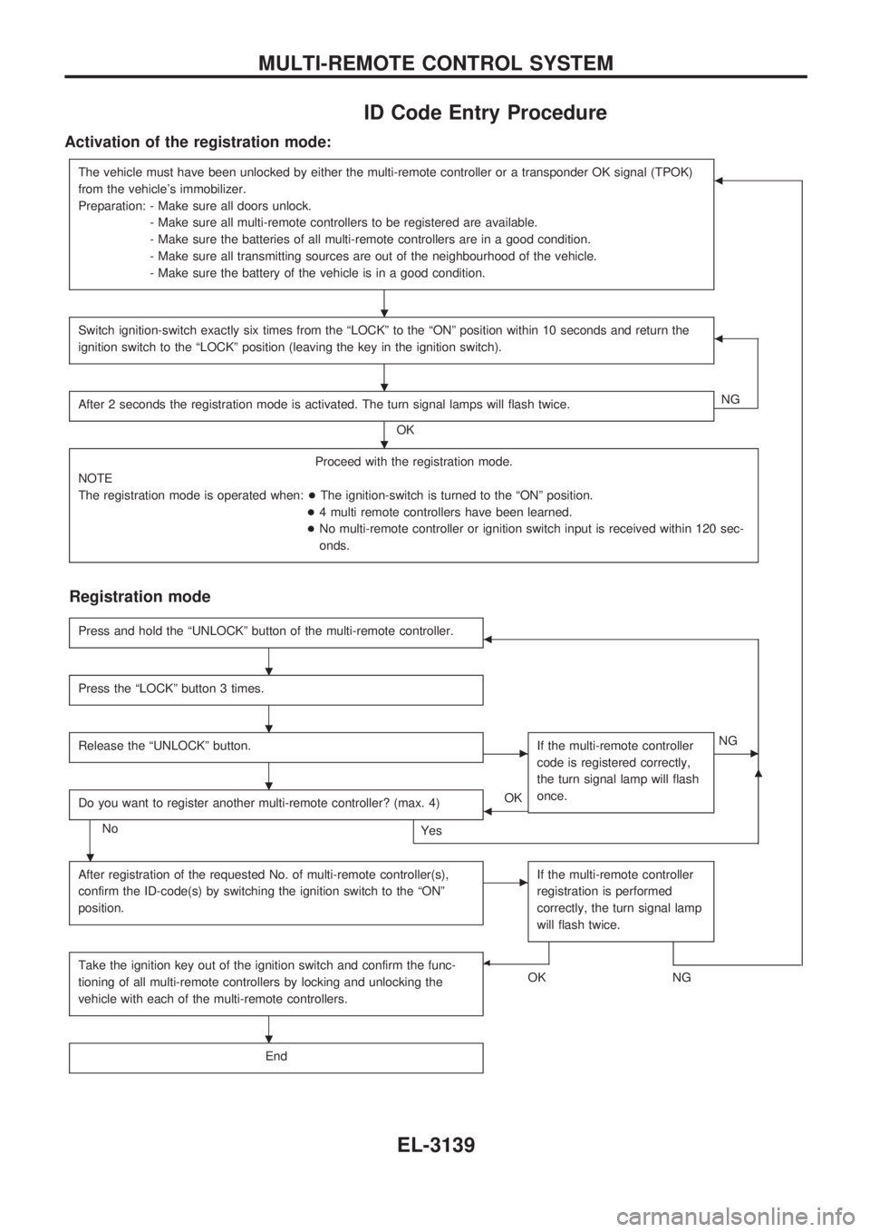
ID Code Entry Procedure
Activation of the registration mode:
The vehicle must have been unlocked by either the multi-remote controller or a transponder OK signal (TPOK)
from the vehicle's immobilizer.
Preparation: - Make sure all doors unlock.
- Make sure all multi-remote controllers to be registered are available.
- Make sure the batteries of all multi-remote controllers are in a good condition.
- Make sure all transmitting sources are out of the neighbourhood of the vehicle.
- Make sure the battery of the vehicle is in a good condition.b
Switch ignition-switch exactly six times from the ªLOCKº to the ªONº position within 10 seconds and return the
ignition switch to the ªLOCKº position (leaving the key in the ignition switch).b
After 2 seconds the registration mode is activated. The turn signal lamps will flash twice.
OKNG
Proceed with the registration mode.
NOTE
The registration mode is operated when:+The ignition-switch is turned to the ªONº position.
+4 multi remote controllers have been learned.
+No multi-remote controller or ignition switch input is received within 120 sec-
onds.
Registration mode
Press and hold the ªUNLOCKº button of the multi-remote controller.b
Press the ªLOCKº button 3 times.
Release the ªUNLOCKº button.cIf the multi-remote controller
code is registered correctly,
the turn signal lamp will flash
once.cNG
Do you want to register another multi-remote controller? (max. 4)
No
Yes
bOK
m
After registration of the requested No. of multi-remote controller(s),
confirm the ID-code(s) by switching the ignition switch to the ªONº
position.cIf the multi-remote controller
registration is performed
correctly, the turn signal lamp
will flash twice.
Take the ignition key out of the ignition switch and confirm the func-
tioning of all multi-remote controllers by locking and unlocking the
vehicle with each of the multi-remote controllers.b
OKNG
End
.
.
.
.
.
.
.
.
MULTI-REMOTE CONTROL SYSTEM
EL-3139
Page 1254 of 1306
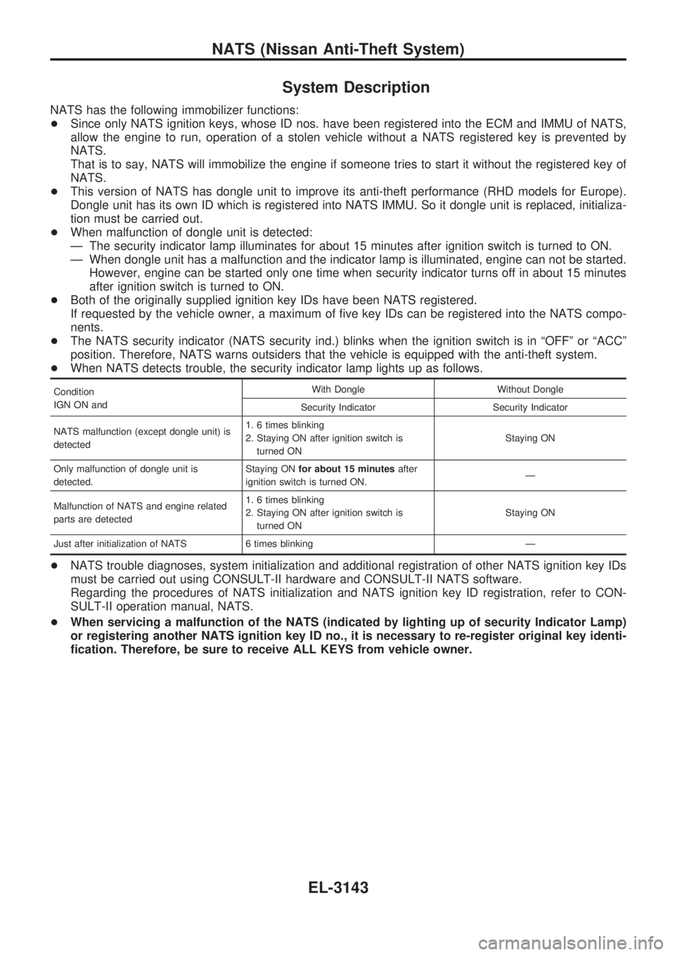
System Description
NATS has the following immobilizer functions:
+Since only NATS ignition keys, whose ID nos. have been registered into the ECM and IMMU of NATS,
allow the engine to run, operation of a stolen vehicle without a NATS registered key is prevented by
NATS.
That is to say, NATS will immobilize the engine if someone tries to start it without the registered key of
NATS.
+This version of NATS has dongle unit to improve its anti-theft performance (RHD models for Europe).
Dongle unit has its own ID which is registered into NATS IMMU. So it dongle unit is replaced, initializa-
tion must be carried out.
+When malfunction of dongle unit is detected:
Ð The security indicator lamp illuminates for about 15 minutes after ignition switch is turned to ON.
Ð When dongle unit has a malfunction and the indicator lamp is illuminated, engine can not be started.
However, engine can be started only one time when security indicator turns off in about 15 minutes
after ignition switch is turned to ON.
+Both of the originally supplied ignition key IDs have been NATS registered.
If requested by the vehicle owner, a maximum of five key IDs can be registered into the NATS compo-
nents.
+The NATS security indicator (NATS security ind.) blinks when the ignition switch is in ªOFFº or ªACCº
position. Therefore, NATS warns outsiders that the vehicle is equipped with the anti-theft system.
+When NATS detects trouble, the security indicator lamp lights up as follows.
Condition
IGN ON andWith Dongle Without Dongle
Security Indicator Security Indicator
NATS malfunction (except dongle unit) is
detected1. 6 times blinking
2. Staying ON after ignition switch is
turned ONStaying ON
Only malfunction of dongle unit is
detected.Staying ONfor about 15 minutesafter
ignition switch is turned ON.Ð
Malfunction of NATS and engine related
parts are detected1. 6 times blinking
2. Staying ON after ignition switch is
turned ONStaying ON
Just after initialization of NATS 6 times blinking Ð
+NATS trouble diagnoses, system initialization and additional registration of other NATS ignition key IDs
must be carried out using CONSULT-II hardware and CONSULT-II NATS software.
Regarding the procedures of NATS initialization and NATS ignition key ID registration, refer to CON-
SULT-II operation manual, NATS.
+When servicing a malfunction of the NATS (indicated by lighting up of security Indicator Lamp)
or registering another NATS ignition key ID no., it is necessary to re-register original key identi-
fication. Therefore, be sure to receive ALL KEYS from vehicle owner.
NATS (Nissan Anti-Theft System)
EL-3143