2001 NISSAN PICK-UP fuel filter
[x] Cancel search: fuel filterPage 58 of 1306

SEC305D
PEF823K
Fuel Pressure ReleaseNEEC0024Before disconnecting fuel line, release fuel pressure from fuel
line to eliminate danger.
WITH CONSULT-IINEEC0024S011. Start engine.
2. Perform ªFUEL PRESSURE RELEASEº in ªWORK SUP-
PORTº mode with CONSULT-II.
3. After engine stalls, crank it two or three times to release all fuel
pressure.
4. Turn ignition switch OFF.
SEC306D
WITHOUT CONSULT-IINEEC0024S021. Remove fuse for fuel pump.
2. Start engine.
3. After engine stalls, crank it two or three times to release all fuel
pressure.
4. Turn ignition switch OFF and reconnect fuel pump fuse.
AEC064B
SEF318V
Fuel Pressure CheckNEEC0025+When reconnecting fuel line, always use new clamps.
+Make sure that clamp screw does not contact adjacent
parts.
+Use a torque driver to tighten clamps.
+Use Pressure Gauge to check fuel pressure.
+Do not perform fuel pressure check with system operat-
ing. Fuel pressure gauge may indicate false readings.
1. Release fuel pressure to zero.
2. Disconnect fuel hose between fuel filter and fuel tube (engine
side).
3. Install pressure gauge between fuel filter and fuel tube.
4. Start engine and check for fuel leakage.
5. Read the indication of fuel pressure gauge.
At idle speed:
With vacuum hose connected
Approximately 235 kPa (2.35 bar, 2.4 kg/cm
2,34
psi)
With vacuum hose disconnected
Approximately 294 kPa (2.94 bar, 3.0 kg/cm
2,43
psi)
BASIC SERVICE PROCEDUREKA24DE (EURO OBD)
Fuel Pressure Release
EC-3033
Page 130 of 1306
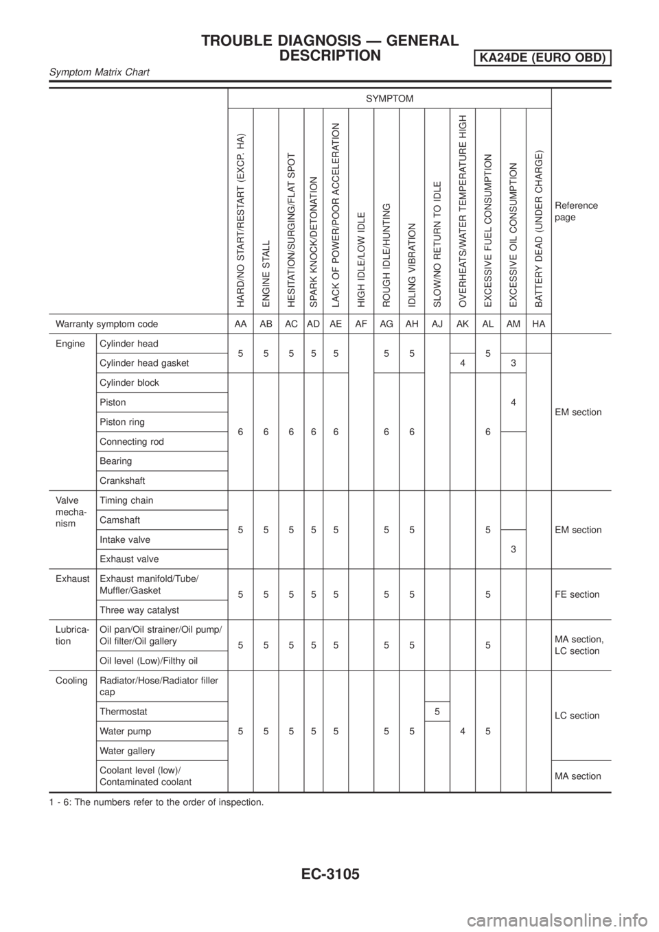
SYMPTOM
Reference
page
HARD/NO START/RESTART (EXCP. HA)
ENGINE STALL
HESITATION/SURGING/FLAT SPOT
SPARK KNOCK/DETONATION
LACK OF POWER/POOR ACCELERATION
HIGH IDLE/LOW IDLE
ROUGH IDLE/HUNTING
IDLING VIBRATION
SLOW/NO RETURN TO IDLE
OVERHEATS/WATER TEMPERATURE HIGH
EXCESSIVE FUEL CONSUMPTION
EXCESSIVE OIL CONSUMPTION
BATTERY DEAD (UNDER CHARGE)
Warranty symptom code AA AB AC AD AE AF AG AH AJ AK AL AM HA
Engine Cylinder head
55555 55 5
EM section Cylinder head gasket 4 3
Cylinder block
66666 66 64 Piston
Piston ring
Connecting rod
Bearing
Crankshaft
Valve
mecha-
nismTiming chain
5 5 5 5 5 5 5 5 EM section Camshaft
Intake valve
3
Exhaust valve
Exhaust Exhaust manifold/Tube/
Muffler/Gasket
5 5 5 5 5 5 5 5 FE section
Three way catalyst
Lubrica-
tionOil pan/Oil strainer/Oil pump/
Oil filter/Oil gallery
55555 55 5MA section,
LC section
Oil level (Low)/Filthy oil
Cooling Radiator/Hose/Radiator filler
cap
55555 55 45LC section Thermostat 5
Water pump
Water gallery
Coolant level (low)/
Contaminated coolantMA section
1 - 6: The numbers refer to the order of inspection.
TROUBLE DIAGNOSIS Ð GENERAL
DESCRIPTION
KA24DE (EURO OBD)
Symptom Matrix Chart
EC-3105
Page 266 of 1306
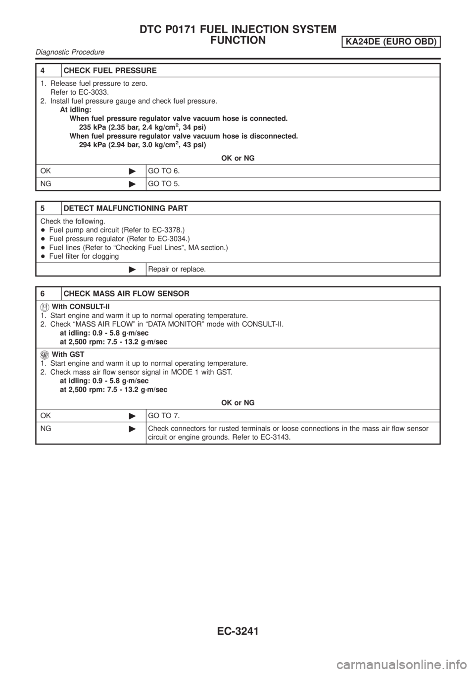
4 CHECK FUEL PRESSURE
1. Release fuel pressure to zero.
Refer to EC-3033.
2. Install fuel pressure gauge and check fuel pressure.
At idling:
When fuel pressure regulator valve vacuum hose is connected.
235 kPa (2.35 bar, 2.4 kg/cm
2, 34 psi)
When fuel pressure regulator valve vacuum hose is disconnected.
294 kPa (2.94 bar, 3.0 kg/cm
2, 43 psi)
OK or NG
OK©GO TO 6.
NG©GO TO 5.
5 DETECT MALFUNCTIONING PART
Check the following.
+Fuel pump and circuit (Refer to EC-3378.)
+Fuel pressure regulator (Refer to EC-3034.)
+Fuel lines (Refer to ªChecking Fuel Linesº, MA section.)
+Fuel filter for clogging
©Repair or replace.
6 CHECK MASS AIR FLOW SENSOR
With CONSULT-II
1. Start engine and warm it up to normal operating temperature.
2. Check ªMASS AIR FLOWº in ªDATA MONITORº mode with CONSULT-II.
at idling: 0.9 - 5.8 g´m/sec
at 2,500 rpm: 7.5 - 13.2 g´m/sec
With GST
1. Start engine and warm it up to normal operating temperature.
2. Check mass air flow sensor signal in MODE 1 with GST.
at idling: 0.9 - 5.8 g´m/sec
at 2,500 rpm: 7.5 - 13.2 g´m/sec
OK or NG
OK©GO TO 7.
NG©Check connectors for rusted terminals or loose connections in the mass air flow sensor
circuit or engine grounds. Refer to EC-3143.
DTC P0171 FUEL INJECTION SYSTEM
FUNCTION
KA24DE (EURO OBD)
Diagnostic Procedure
EC-3241
Page 281 of 1306
10 DETECT MALFUNCTIONING PART
Check the following.
+Fuel pump and circuit (Refer to EC-3378.)
+Fuel pressure regulator (Refer to EC-3034.)
+Fuel lines (Refer to ªChecking Fuel Linesº, MA section).
+Fuel filter for clogging
©Repair or replace.
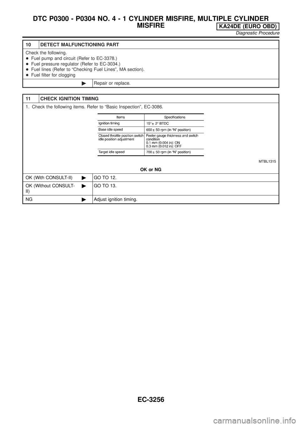
11 CHECK IGNITION TIMING
1. Check the following items. Refer to ªBasic Inspectionº, EC-3086.
MTBL1315
OK or NG
OK (With CONSULT-II)©GO TO 12.
OK (Without CONSULT-
II)©GO TO 13.
NG©Adjust ignition timing.
DTC P0300 - P0304 NO.4-1CYLINDER MISFIRE, MULTIPLE CYLINDER
MISFIRE
KA24DE (EURO OBD)
Diagnostic Procedure
EC-3256
Page 428 of 1306
tion due to receiving external noise, degraded operation
of ICs, etc.
+Keep engine control system parts and harnesses dry.
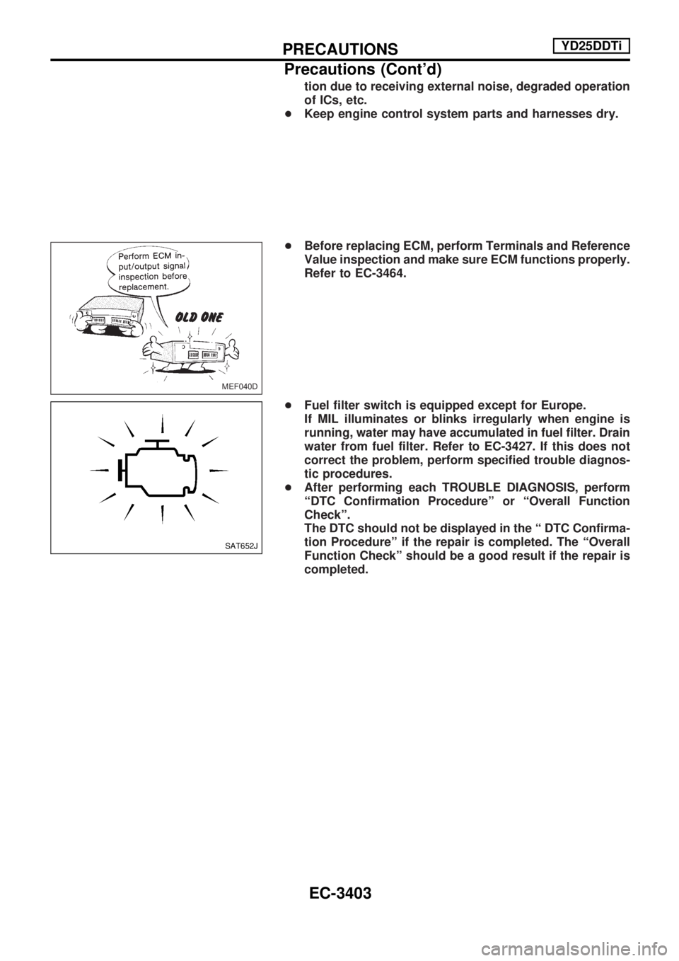
+Before replacing ECM, perform Terminals and Reference
Value inspection and make sure ECM functions properly.
Refer to EC-3464.
+Fuel filter switch is equipped except for Europe.
If MIL illuminates or blinks irregularly when engine is
running, water may have accumulated in fuel filter. Drain
water from fuel filter. Refer to EC-3427. If this does not
correct the problem, perform specified trouble diagnos-
tic procedures.
+After performing each TROUBLE DIAGNOSIS, perform
ªDTC Confirmation Procedureº or ªOverall Function
Checkº.
The DTC should not be displayed in the ª DTC Confirma-
tion Procedureº if the repair is completed. The ªOverall
Function Checkº should be a good result if the repair is
completed.
MEF040D
SAT652J
PRECAUTIONSYD25DDTi
Precautions (Cont'd)
EC-3403
Page 451 of 1306
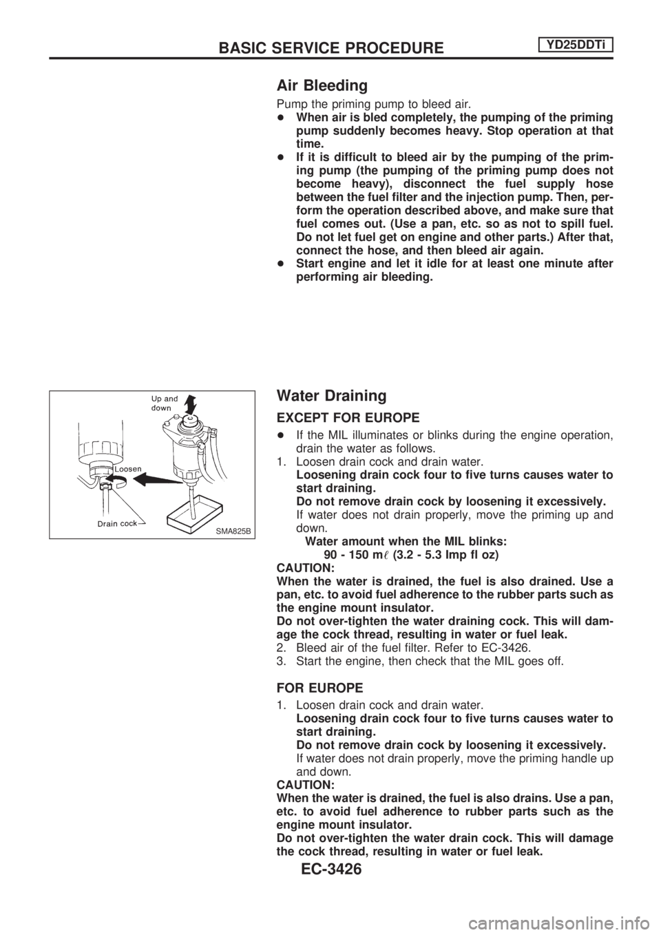
Air Bleeding
Pump the priming pump to bleed air.
+When air is bled completely, the pumping of the priming
pump suddenly becomes heavy. Stop operation at that
time.
+If it is difficult to bleed air by the pumping of the prim-
ing pump (the pumping of the priming pump does not
become heavy), disconnect the fuel supply hose
between the fuel filter and the injection pump. Then, per-
form the operation described above, and make sure that
fuel comes out. (Use a pan, etc. so as not to spill fuel.
Do not let fuel get on engine and other parts.) After that,
connect the hose, and then bleed air again.
+Start engine and let it idle for at least one minute after
performing air bleeding.
Water Draining
EXCEPT FOR EUROPE
+If the MIL illuminates or blinks during the engine operation,
drain the water as follows.
1. Loosen drain cock and drain water.
Loosening drain cock four to five turns causes water to
start draining.
Do not remove drain cock by loosening it excessively.
If water does not drain properly, move the priming up and
down.
Water amount when the MIL blinks:
90 - 150 m!(3.2 - 5.3 Imp fl oz)
CAUTION:
When the water is drained, the fuel is also drained. Use a
pan, etc. to avoid fuel adherence to the rubber parts such as
the engine mount insulator.
Do not over-tighten the water draining cock. This will dam-
age the cock thread, resulting in water or fuel leak.
2. Bleed air of the fuel filter. Refer to EC-3426.
3. Start the engine, then check that the MIL goes off.
FOR EUROPE
1. Loosen drain cock and drain water.
Loosening drain cock four to five turns causes water to
start draining.
Do not remove drain cock by loosening it excessively.
If water does not drain properly, move the priming handle up
and down.
CAUTION:
When the water is drained, the fuel is also drains. Use a pan,
etc. to avoid fuel adherence to rubber parts such as the
engine mount insulator.
Do not over-tighten the water drain cock. This will damage
the cock thread, resulting in water or fuel leak.
SMA825B
BASIC SERVICE PROCEDUREYD25DDTi
EC-3426
Page 452 of 1306
2. Bleed air of the fuel filter. Refer to EC-3426.
Accelerator Position Sensor Idle Position
Learning
DESCRIPTION
ªAccelerator Position Sensor Idle Position Learningº is an opera-
tion to clear the self-learning fully closed accelerator position.
It must be performed each time harness connector of accelera-
tor position sensor or ECM is disconnected.
OPERATION PROCEDURE
With CONSULT-II
1. Turn ignition switch ªONº.
2. Select ªOFF ACCEL PO SIGº in ªACTIVE TESTº mode with
CONSULT-II.
3. Touch ªCLEARº.
Without CONSULT-II
1. Start engine and warm it up to normal operating temperature.
2. Let engine idle for 10 minutes.
BASIC SERVICE PROCEDUREYD25DDTi
EC-3427
Page 454 of 1306
+Erasing the emission-related diagnostic information using CONSULT-II is easier and quicker than
switching the diagnostic test mode using the data link connector.
NATS (Nissan Anti-Theft System)
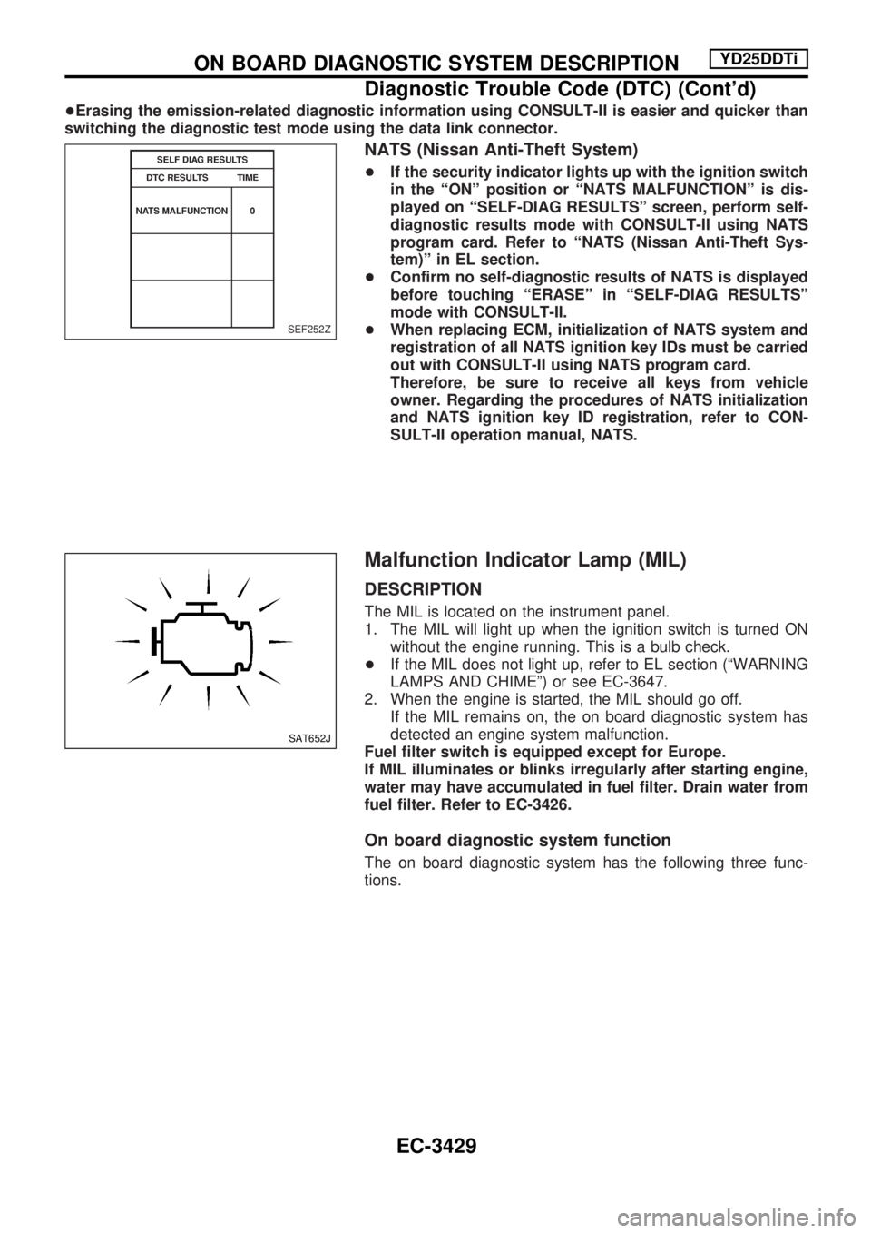
+If the security indicator lights up with the ignition switch
in the ªONº position or ªNATS MALFUNCTIONº is dis-
played on ªSELF-DIAG RESULTSº screen, perform self-
diagnostic results mode with CONSULT-II using NATS
program card. Refer to ªNATS (Nissan Anti-Theft Sys-
tem)º in EL section.
+Confirm no self-diagnostic results of NATS is displayed
before touching ªERASEº in ªSELF-DIAG RESULTSº
mode with CONSULT-II.
+When replacing ECM, initialization of NATS system and
registration of all NATS ignition key IDs must be carried
out with CONSULT-II using NATS program card.
Therefore, be sure to receive all keys from vehicle
owner. Regarding the procedures of NATS initialization
and NATS ignition key ID registration, refer to CON-
SULT-II operation manual, NATS.
Malfunction Indicator Lamp (MIL)
DESCRIPTION
The MIL is located on the instrument panel.
1. The MIL will light up when the ignition switch is turned ON
without the engine running. This is a bulb check.
+If the MIL does not light up, refer to EL section (ªWARNING
LAMPS AND CHIMEº) or see EC-3647.
2. When the engine is started, the MIL should go off.
If the MIL remains on, the on board diagnostic system has
detected an engine system malfunction.
Fuel filter switch is equipped except for Europe.
If MIL illuminates or blinks irregularly after starting engine,
water may have accumulated in fuel filter. Drain water from
fuel filter. Refer to EC-3426.
On board diagnostic system function
The on board diagnostic system has the following three func-
tions.
SEF252Z
SAT652J
ON BOARD DIAGNOSTIC SYSTEM DESCRIPTIONYD25DDTi
Diagnostic Trouble Code (DTC) (Cont'd)
EC-3429