2001 NISSAN PICK-UP tow
[x] Cancel search: towPage 99 of 1306
![NISSAN PICK-UP 2001 Repair Manual Freeze frame data
item*Description
INT/A TEMP SE [ÉC]
or [ÉF]+The intake air temperature at the moment a malfunction is detected is displayed.
*: The items are the same as those of 1st trip freeze f NISSAN PICK-UP 2001 Repair Manual Freeze frame data
item*Description
INT/A TEMP SE [ÉC]
or [ÉF]+The intake air temperature at the moment a malfunction is detected is displayed.
*: The items are the same as those of 1st trip freeze f](/manual-img/5/57372/w960_57372-98.png)
Freeze frame data
item*Description
INT/A TEMP SE [ÉC]
or [ÉF]+The intake air temperature at the moment a malfunction is detected is displayed.
*: The items are the same as those of 1st trip freeze frame data.
DATA MONITOR MODENEEC0034S06
Monitored item [Unit]ECM
input
signalsMain
signalsDescription Remarks
ENG SPEED [rpm]jj+Indicates the engine speed computed
from the REF signal (180É signal) of
the camshaft position sensor.+Accuracy becomes poor if engine
speed drops below the idle rpm.
+If the signal is interrupted while the
engine is running, an abnormal value
may be indicated.
MAS A/F SE-B1 [V]jj+The signal voltage of the mass air flow
sensor is displayed.+When the engine is stopped, a cer-
tain value is indicated.
B/FUEL SCHDL [msec]j+ªBase fuel scheduleº indicates the fuel
injection pulse width programmed into
ECM, prior to any learned on board
correction.
A/F ALPHA-B1 [%]j+Indicates the mean value of the air-fuel
ratio feedback correction factor per
cycle.+When the engine is stopped, a cer-
tain value is indicated.
+This data also includes the data for
the air-fuel ratio learning control.
COOLAN TEMP/S
[ÉC] or [ÉF]jj+The engine coolant temperature (deter-
mined by the signal voltage of the
engine coolant temperature sensor) is
displayed.+When the engine coolant temperature
sensor is open or short-circuited,
ECM enters fail-safe mode. The
engine coolant temperature deter-
mined by the ECM is displayed.
HO2S1 (B1) [V]jj+The signal voltage of the heated oxy-
gen sensor 1 is displayed.
HO2S2 (B1) [V]j+The signal voltage of the heated oxy-
gen sensor 2 is displayed.
HO2S1 MNTR (B1)
[RICH/LEAN]jj+Display of heated oxygen sensor 1 sig-
nal during air-fuel ratio feedback con-
trol:
RICH ... means the mixture became
ªrichº, and control is being affected
toward a leaner mixture.
LEAN ... means the mixture became
ªleanº, and control is being affected
toward a rich mixture.+After turning ON the ignition switch,
ªRICHº is displayed until air-fuel mix-
ture ratio feedback control begins.
+When the air-fuel ratio feedback is
clamped, the value just before the
clamping is displayed continuously.
HO2S2 MNTR (B1)
[RICH/LEAN]j+Display of heated oxygen sensor 2 sig-
nal:
RICH ... means the amount of oxygen
after three way catalyst is relatively
small.
LEAN ... means the amount of oxygen
after three way catalyst is relatively
large.+When the engine is stopped, a cer-
tain value is indicated.
VHCL SPEED SE
[km/h] or [mph]jj+The vehicle speed computed from the
vehicle speed sensor signal is dis-
played.
BATTERY VOLT [V]jj+The power supply voltage of ECM is
displayed.
ON BOARD DIAGNOSTIC SYSTEM
DESCRIPTION
KA24DE (EURO OBD)
CONSULT-II
EC-3074
Page 447 of 1306
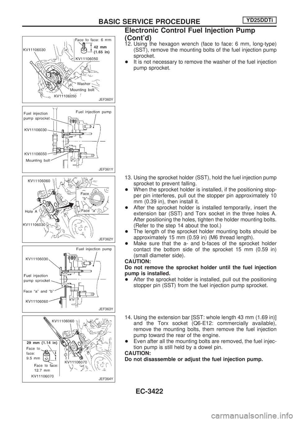
12. Using the hexagon wrench (face to face: 6 mm, long-type)
(SST), remove the mounting bolts of the fuel injection pump
sprocket.
+It is not necessary to remove the washer of the fuel injection
pump sprocket.
13. Using the sprocket holder (SST), hold the fuel injection pump
sprocket to prevent falling.
+When the sprocket holder is installed, if the positioning stop-
per pin interferes, pull out the stopper pin approximately 10
mm (0.39 in), then install it.
+After the sprocket holder is installed temporarily, insert the
extension bar (SST) and Torx socket in the three holes A.
After positioning the holes, tighten the holder mounting bolts.
(Refer to the step 14 about the tool.)
+The length of the sprocket holder mounting bolts should be
approximately 15 mm (0.59 in) (M6 thread length).
+Make sure that the a- and b-faces of the sprocket holder
contact the bottom side of the sprocket 15 mm (0.59 in)
(small diameter side).
CAUTION:
Do not remove the sprocket holder until the fuel injection
pump is installed.
+After the sprocket holder is installed, pull out the positioning
stopper pin (SST) from the fuel injection pump sprocket.
14. Using the extension bar [SST: whole length 43 mm (1.69 in)]
and the Torx socket (Q6-E12: commercially available),
remove the mounting bolts, them remove the fuel injection
pump toward the rear of the engine.
+Even after all the mounting bolts are removed, the fuel injec-
tion pump is still held by a dowel pin.
CAUTION:
Do not disassemble or adjust the fuel injection pump.
JEF360Y
JEF361Y
JEF362Y
JEF363Y
JEF364Y
BASIC SERVICE PROCEDUREYD25DDTi
Electronic Control Fuel Injection Pump
(Cont'd)
EC-3422
Page 926 of 1306
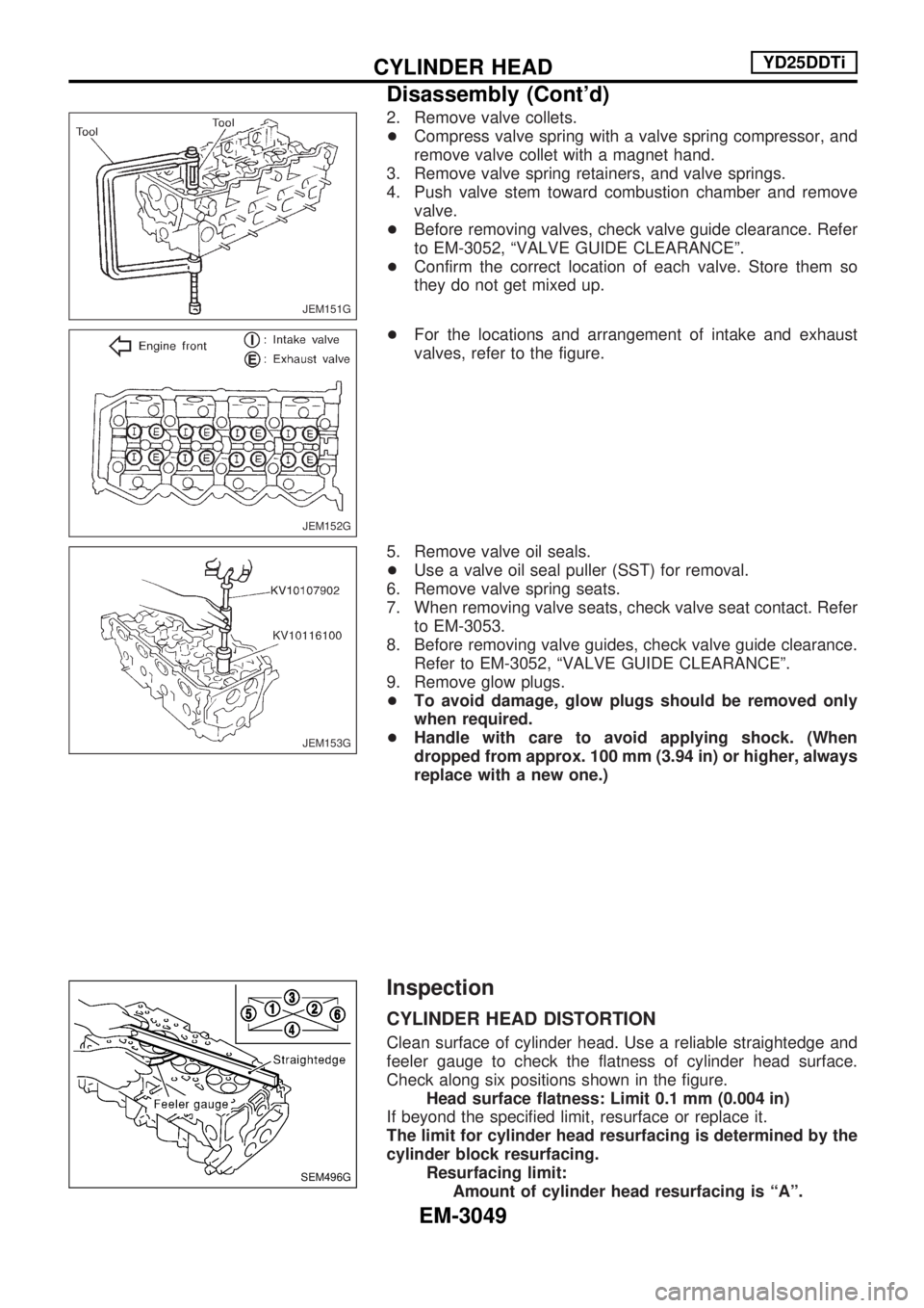
2. Remove valve collets.
+Compress valve spring with a valve spring compressor, and
remove valve collet with a magnet hand.
3. Remove valve spring retainers, and valve springs.
4. Push valve stem toward combustion chamber and remove valve.
+ Before removing valves, check valve guide clearance. Refer
to EM-3052, ªVALVE GUIDE CLEARANCEº.
+ Confirm the correct location of each valve. Store them so
they do not get mixed up.
+ For the locations and arrangement of intake and exhaust
valves, refer to the figure.
5. Remove valve oil seals.
+ Use a valve oil seal puller (SST) for removal.
6. Remove valve spring seats.
7. When removing valve seats, check valve seat contact. Refer to EM-3053.
8. Before removing valve guides, check valve guide clearance. Refer to EM-3052, ªVALVE GUIDE CLEARANCEº.
9. Remove glow plugs.
+ To avoid damage, glow plugs should be removed only
when required.
+ Handle with care to avoid applying shock. (When
dropped from approx. 100 mm (3.94 in) or higher, always
replace with a new one.)
Inspection
CYLINDER HEAD DISTORTION
Clean surface of cylinder head. Use a reliable straightedge and
feeler gauge to check the flatness of cylinder head surface.
Check along six positions shown in the figure.
Headsurfaceflatness:Limit0.1 mm(0.004 in)
If beyond the specified limit, resurface or replace it.
The limit for cylinder head resurfacing is determined by the
cylinder block resurfacing. Resurfacing limit:Amount of cylinder head resurfacing is ªAº.
JEM151G
JEM152G
JEM153G
SEM496G
CYLINDER HEADYD25DDTi
Disassembly (Cont'd)
EM-3049
Page 929 of 1306
VALVE GUIDE CLEARANCE
1. Check that valve stem diameter is within the specified range.
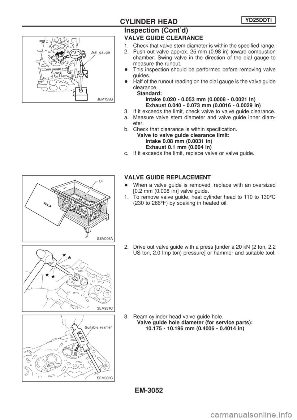
2. Push out valve approx. 25 mm (0.98 in) toward combustion
chamber. Swing valve in the direction of the dial gauge to
measure the runout.
+This inspection should be performed before removing valve
guides.
+Half of the runout reading on the dial gauge is the valve guide
clearance.
Standard:
Intake 0.020 - 0.053 mm (0.0008 - 0.0021 in)
Exhaust 0.040 - 0.073 mm (0.0016 - 0.0029 in)
3. If it exceeds the limit, check valve to valve guide clearance.
a. Measure valve stem diameter and valve guide inner diam-
eter.
b. Check that clearance is within specification.
Valve to valve guide clearance limit:
Intake 0.08 mm (0.0031 in)
Exhaust 0.1 mm (0.004 in)
c. If it exceeds the limit, replace valve or valve guide.
VALVE GUIDE REPLACEMENT
+When a valve guide is removed, replace with an oversized
[0.2 mm (0.008 in)] valve guide.
1. To remove valve guide, heat cylinder head to 110 to 130ÉC
(230 to 266ÉF) by soaking in heated oil.
2. Drive out valve guide with a press [under a 20 kN (2 ton, 2.2
US ton, 2.0 Imp ton) pressure] or hammer and suitable tool.
3. Ream cylinder head valve guide hole.
Valve guide hole diameter (for service parts):
10.175 - 10.196 mm (0.4006 - 0.4014 in)
JEM155G
SEM008A
SEM931C
SEM932C
CYLINDER HEADYD25DDTi
Inspection (Cont'd)
EM-3052
Page 938 of 1306
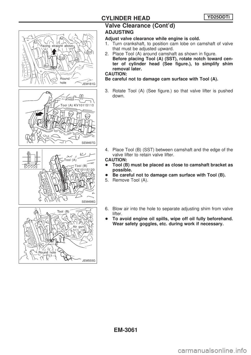
ADJUSTING
Adjust valve clearance while engine is cold.
1. Turn crankshaft, to position cam lobe on camshaft of valve
that must be adjusted upward.
2. Place Tool (A) around camshaft as shown in figure.
Before placing Tool (A) (SST), rotate notch toward cen-
ter of cylinder head (See figure.), to simplify shim
removal later.
CAUTION:
Be careful not to damage cam surface with Tool (A).
3. Rotate Tool (A) (See figure.) so that valve lifter is pushed
down.
4. Place Tool (B) (SST) between camshaft and the edge of the
valve lifter to retain valve lifter.
CAUTION:
+Tool (B) must be placed as close to camshaft bracket as
possible.
+Be careful not to damage cam surface with Tool (B).
5. Remove Tool (A).
6. Blow air into the hole to separate adjusting shim from valve
lifter.
+To avoid engine oil spills, wipe off oil fully beforehand.
Wear safety goggles, etc. during work if necessary.
JEM181G
SEM497G
SEM498G
JEM555G
CYLINDER HEADYD25DDTi
Valve Clearance (Cont'd)
EM-3061
Page 945 of 1306
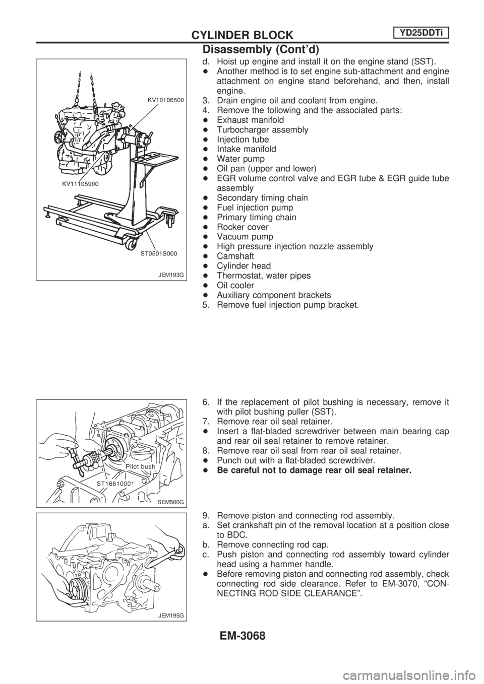
d. Hoist up engine and install it on the engine stand (SST).
+Another method is to set engine sub-attachment and engine
attachment on engine stand beforehand, and then, install
engine.
3. Drain engine oil and coolant from engine.
4. Remove the following and the associated parts:
+Exhaust manifold
+Turbocharger assembly
+Injection tube
+Intake manifold
+Water pump
+Oil pan (upper and lower)
+EGR volume control valve and EGR tube & EGR guide tube
assembly
+Secondary timing chain
+Fuel injection pump
+Primary timing chain
+Rocker cover
+Vacuum pump
+High pressure injection nozzle assembly
+Camshaft
+Cylinder head
+Thermostat, water pipes
+Oil cooler
+Auxiliary component brackets
5. Remove fuel injection pump bracket.
6. If the replacement of pilot bushing is necessary, remove it
with pilot bushing puller (SST).
7. Remove rear oil seal retainer.
+Insert a flat-bladed screwdriver between main bearing cap
and rear oil seal retainer to remove retainer.
8. Remove rear oil seal from rear oil seal retainer.
+Punch out with a flat-bladed screwdriver.
+Be careful not to damage rear oil seal retainer.
9. Remove piston and connecting rod assembly.
a. Set crankshaft pin of the removal location at a position close
to BDC.
b. Remove connecting rod cap.
c. Push piston and connecting rod assembly toward cylinder
head using a hammer handle.
+Before removing piston and connecting rod assembly, check
connecting rod side clearance. Refer to EM-3070, ªCON-
NECTING ROD SIDE CLEARANCEº.
JEM193G
SEM500G
JEM195G
CYLINDER BLOCKYD25DDTi
Disassembly (Cont'd)
EM-3068
Page 960 of 1306
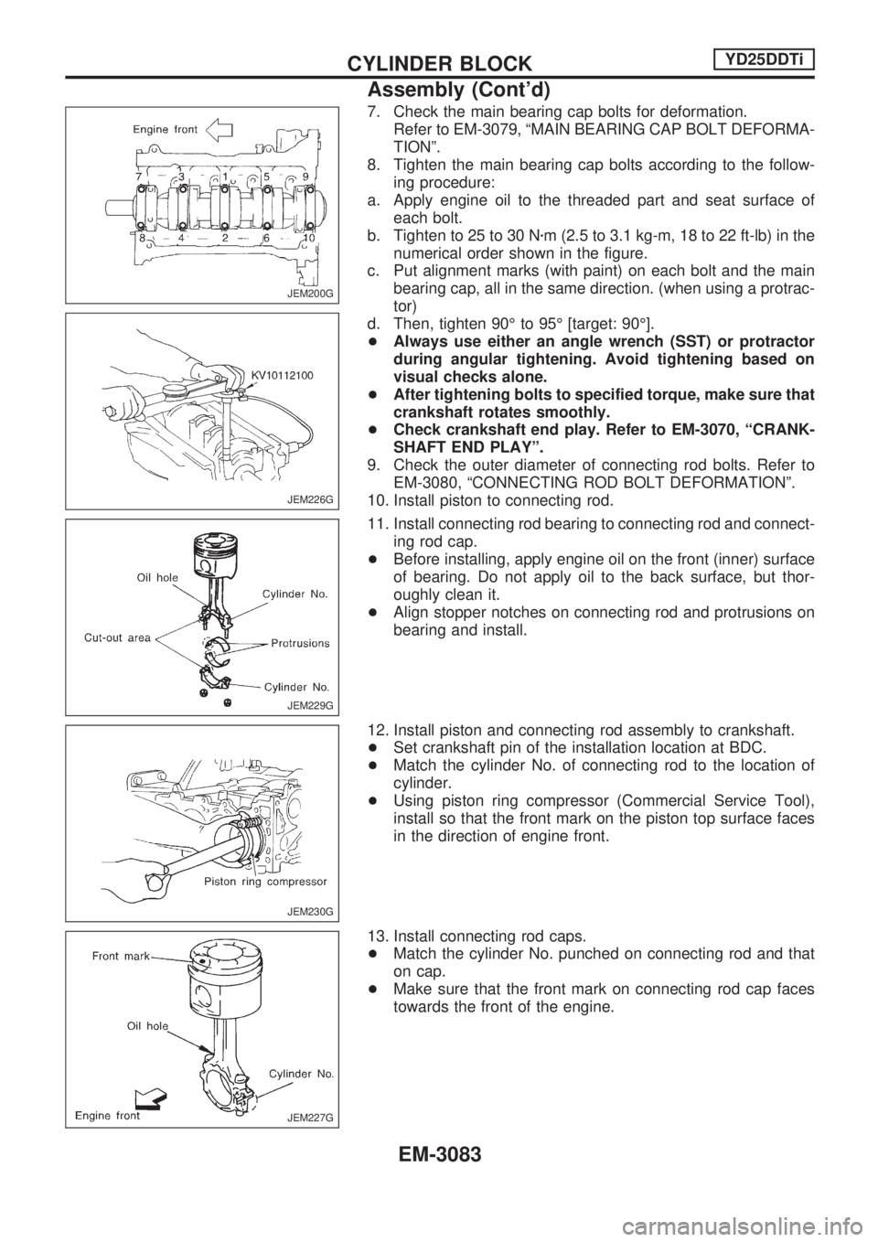
7. Check the main bearing cap bolts for deformation.
Refer to EM-3079, ªMAIN BEARING CAP BOLT DEFORMA-
TIONº.
8. Tighten the main bearing cap bolts according to the follow-
ing procedure:
a. Apply engine oil to the threaded part and seat surface of
each bolt.
b. Tighten to 25 to 30 Nzm (2.5 to 3.1 kg-m, 18 to 22 ft-lb) in the
numerical order shown in the figure.
c. Put alignment marks (with paint) on each bolt and the main
bearing cap, all in the same direction. (when using a protrac-
tor)
d. Then, tighten 90É to 95É [target: 90É].
+Always use either an angle wrench (SST) or protractor
during angular tightening. Avoid tightening based on
visual checks alone.
+After tightening bolts to specified torque, make sure that
crankshaft rotates smoothly.
+Check crankshaft end play. Refer to EM-3070, ªCRANK-
SHAFT END PLAYº.
9. Check the outer diameter of connecting rod bolts. Refer to
EM-3080, ªCONNECTING ROD BOLT DEFORMATIONº.
10. Install piston to connecting rod.
11. Install connecting rod bearing to connecting rod and connect-
ing rod cap.
+Before installing, apply engine oil on the front (inner) surface
of bearing. Do not apply oil to the back surface, but thor-
oughly clean it.
+Align stopper notches on connecting rod and protrusions on
bearing and install.
12. Install piston and connecting rod assembly to crankshaft.
+Set crankshaft pin of the installation location at BDC.
+Match the cylinder No. of connecting rod to the location of
cylinder.
+Using piston ring compressor (Commercial Service Tool),
install so that the front mark on the piston top surface faces
in the direction of engine front.
13. Install connecting rod caps.
+Match the cylinder No. punched on connecting rod and that
on cap.
+Make sure that the front mark on connecting rod cap faces
towards the front of the engine.
JEM200G
JEM226G
JEM229G
JEM230G
JEM227G
CYLINDER BLOCKYD25DDTi
Assembly (Cont'd)
EM-3083
Page 1026 of 1306
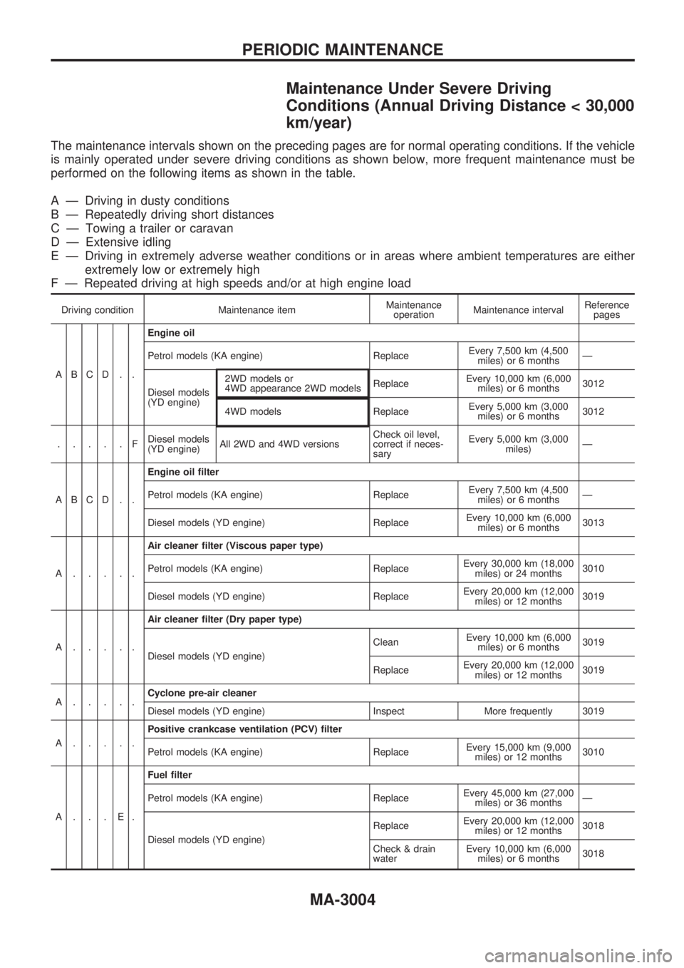
Maintenance Under Severe Driving
Conditions (Annual Driving Distance < 30,000
km/year)
The maintenance intervals shown on the preceding pages are for normal operating conditions. If the vehicle
is mainly operated under severe driving conditions as shown below, more frequent maintenance must be
performed on the following items as shown in the table.
A Ð Driving in dusty conditions
B Ð Repeatedly driving short distances
C Ð Towing a trailer or caravan
D Ð Extensive idling
E Ð Driving in extremely adverse weather conditions or in areas where ambient temperatures are either
extremely low or extremely high
F Ð Repeated driving at high speeds and/or at high engine load
Driving condition Maintenance itemMaintenance
operationMaintenance intervalReference
pages
ABCD . .
Engine oil
Petrol models (KA engine) ReplaceEvery 7,500 km (4,500
miles) or 6 monthsÐ
Diesel models
(YD engine)2WD models or
4WD appearance 2WD modelsReplaceEvery 10,000 km (6,000
miles) or 6 months3012
4WD models ReplaceEvery 5,000 km (3,000
miles) or 6 months3012
.....FDiesel models
(YD engine)All 2WD and 4WD versionsCheck oil level,
correct if neces-
saryEvery 5,000 km (3,000
miles)Ð
ABCD . .Engine oil filter
Petrol models (KA engine) ReplaceEvery 7,500 km (4,500
miles) or 6 monthsÐ
Diesel models (YD engine) ReplaceEvery 10,000 km (6,000
miles) or 6 months3013
A.....Air cleaner filter (Viscous paper type)
Petrol models (KA engine) ReplaceEvery 30,000 km (18,000
miles) or 24 months3010
Diesel models (YD engine) ReplaceEvery 20,000 km (12,000
miles) or 12 months3019
A.....Air cleaner filter (Dry paper type)
Diesel models (YD engine)CleanEvery 10,000 km (6,000
miles) or 6 months3019
ReplaceEvery 20,000 km (12,000
miles) or 12 months3019
A.....Cyclone pre-air cleaner
Diesel models (YD engine) Inspect More frequently 3019
A.....Positive crankcase ventilation (PCV) filter
Petrol models (KA engine) ReplaceEvery 15,000 km (9,000
miles) or 12 months3010
A...E.Fuel filter
Petrol models (KA engine) ReplaceEvery 45,000 km (27,000
miles) or 36 monthsÐ
Diesel models (YD engine)ReplaceEvery 20,000 km (12,000
miles) or 12 months3018
Check & drain
waterEvery 10,000 km (6,000
miles) or 6 months3018
PERIODIC MAINTENANCE
MA-3004