2001 NISSAN PICK-UP maintenance
[x] Cancel search: maintenancePage 1042 of 1306

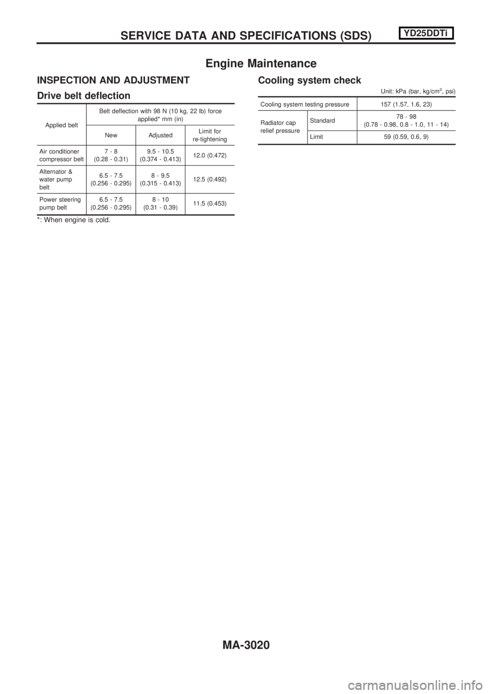
Engine Maintenance
INSPECTION AND ADJUSTMENT
Drive belt deflection
Applied beltBelt deflection with 98 N (10 kg, 22 lb) force
applied* mm (in)
New Adjusted Limit for
re-tightening
Air conditioner
compressor belt 7-8
(0.28 - 0.31) 9.5 - 10.5
(0.374 - 0.413) 12.0 (0.472)
Alternator &
water pump
belt 6.5 - 7.5
(0.256 - 0.295) 8 - 9.5
(0.315 - 0.413) 12.5 (0.492)
Power steering
pump belt 6.5 - 7.5
(0.256 - 0.295) 8-10
(0.31 - 0.39) 11.5 (0.453)
*: When engine is cold.
Cooling system check
Unit: kPa (bar, kg/cm2, psi)
Cooling system testing pressure 157 (1.57, 1.6, 23)
Radiator cap
relief pressureStandard
78-98
(0.78 - 0.98, 0.8 - 1.0, 11 - 14)
Limit 59 (0.59, 0.6, 9)
SERVICEDATAANDSPECIFICATIONS(SDS) YD25DDTi
MA-3020
Page 1064 of 1306

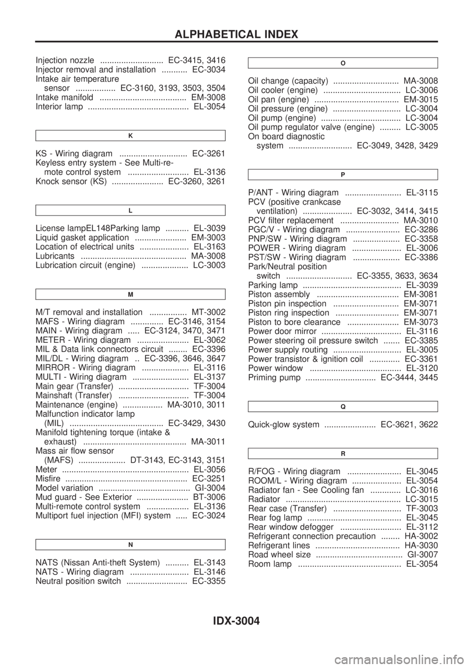
Injection nozzle ........................... EC-3415, 3416
Injector removal and installation ........... EC-3034
Intake air temperature
sensor ................. EC-3160, 3193, 3503, 3504
Intake manifold ..................................... EM-3008
Interior lamp ........................................... EL-3054
K
KS - Wiring diagram ............................. EC-3261
Keyless entry system - See Multi-re-
mote control system .......................... EL-3136
Knock sensor (KS) ...................... EC-3260, 3261
L
License lampEL148Parking lamp .......... EL-3039
Liquid gasket application ...................... EM-3003
Location of electrical units ..................... EL-3163
Lubricants ............................................. MA-3008
Lubrication circuit (engine) .................... LC-3003
M
M/T removal and installation ................ MT-3002
MAFS - Wiring diagram .............. EC-3146, 3154
MAIN - Wiring diagram ..... EC-3124, 3470, 3471
METER - Wiring diagram ...................... EL-3062
MIL & Data link connectors circuit ........ EC-3396
MIL/DL - Wiring diagram .. EC-3396, 3646, 3647
MIRROR - Wiring diagram .................... EL-3116
MULTI - Wiring diagram ........................ EL-3137
Main gear (Transfer) .............................. TF-3004
Mainshaft (Transfer) .............................. TF-3004
Maintenance (engine) ................. MA-3010, 3011
Malfunction indicator lamp
(MIL) ........................................ EC-3429, 3430
Manifold tightening torque (intake &
exhaust) ............................................ MA-3011
Mass air flow sensor
(MAFS) .................... DT-3143, EC-3143, 3151
Meter ...................................................... EL-3056
Misfire .................................................... EC-3251
Model variation ....................................... GI-3004
Mud guard - See Exterior ...................... BT-3006
Multi-remote control system .................. EL-3136
Multiport fuel injection (MFI) system ..... EC-3024
N
NATS (Nissan Anti-theft System) .......... EL-3143
NATS - Wiring diagram ......................... EL-3146
Neutral position switch .......................... EC-3355
O
Oil change (capacity) ............................ MA-3008
Oil cooler (engine) ................................. LC-3006
Oil pan (engine) .................................... EM-3015
Oil pressure (engine) ............................. LC-3004
Oil pump (engine) .................................. LC-3004
Oil pump regulator valve (engine) ......... LC-3005
On board diagnostic
system ........................... EC-3049, 3428, 3429
P
P/ANT - Wiring diagram ........................ EL-3115
PCV (positive crankcase
ventilation) ..................... EC-3032, 3414, 3415
PCV filter replacement ......................... MA-3010
PGC/V - Wiring diagram ....................... EC-3286
PNP/SW - Wiring diagram .................... EC-3358
POWER - Wiring diagram ..................... EL-3006
PST/SW - Wiring diagram .................... EC-3386
Park/Neutral position
switch ............................ EC-3355, 3633, 3634
Parking lamp .......................................... EL-3039
Piston assembly ................................... EM-3081
Piston pin inspection ............................ EM-3071
Piston ring inspection ........................... EM-3071
Piston to bore clearance ...................... EM-3073
Power door mirror .................................. EL-3116
Power steering oil pressure switch ....... EC-3385
Power supply routing ............................. EL-3005
Power transistor & ignition coil ............. EC-3361
Power window ....................................... EL-3120
Priming pump .............................. EC-3444, 3445
Q
Quick-glow system ...................... EC-3621, 3622
R
R/FOG - Wiring diagram ....................... EL-3045
ROOM/L - Wiring diagram ..................... EL-3054
Radiator fan - See Cooling fan ............. LC-3016
Radiator ................................................. LC-3015
Rear case (Transfer) ............................. TF-3003
Rear fog lamp ........................................ EL-3045
Rear window defogger .......................... EL-3112
Refrigerant connection precaution ........ HA-3002
Refrigerant lines .................................... HA-3030
Road wheel size ..................................... GI-3007
Room lamp ............................................ EL-3054
ALPHABETICAL INDEX
IDX-3004
Page 1073 of 1306

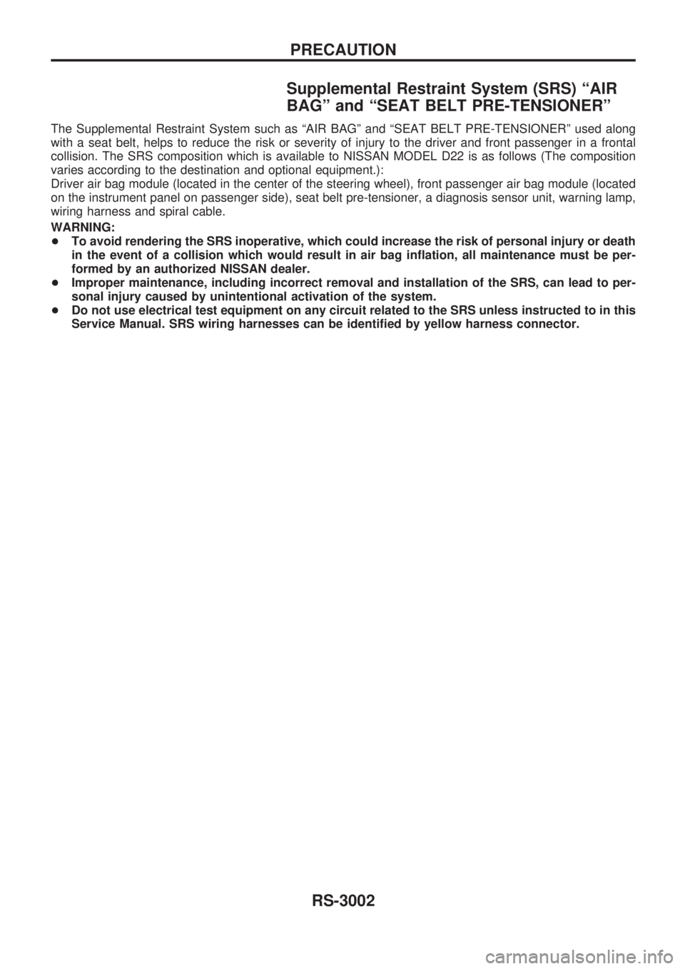
Supplemental Restraint System (SRS) ªAIR
BAGº and ªSEAT BELT PRE-TENSIONERº
The Supplemental Restraint System such as ªAIR BAGº and ªSEAT BELT PRE-TENSIONERº used along
with a seat belt, helps to reduce the risk or severity of injury to the driver and front passenger in a frontal
collision. The SRS composition which is available to NISSAN MODEL D22 is as follows (The composition
varies according to the destination and optional equipment.):
Driver air bag module (located in the center of the steering wheel), front passenger air bag module (located
on the instrument panel on passenger side), seat belt pre-tensioner, a diagnosis sensor unit, warning lamp,
wiring harness and spiral cable.
WARNING:
+To avoid rendering the SRS inoperative, which could increase the risk of personal injury or death
in the event of a collision which would result in air bag inflation, all maintenance must be per-
formed by an authorized NISSAN dealer.
+Improper maintenance, including incorrect removal and installation of the SRS, can lead to per-
sonal injury caused by unintentional activation of the system.
+Do not use electrical test equipment on any circuit related to the SRS unless instructed to in this
Service Manual. SRS wiring harnesses can be identified by yellow harness connector.
PRECAUTION
RS-3002
Page 1103 of 1306
![NISSAN PICK-UP 2001 Repair Manual DIAGNOSTIC PROCEDURE 6 (Continued from
DIAGNOSTIC PROCEDURE 2)
Inspecting SRS malfunctioning record
Is it the first time for maintenance of
SRS?
Yes
cNo
ªSELF-DIAG [PAST]º
(which was previously
ente NISSAN PICK-UP 2001 Repair Manual DIAGNOSTIC PROCEDURE 6 (Continued from
DIAGNOSTIC PROCEDURE 2)
Inspecting SRS malfunctioning record
Is it the first time for maintenance of
SRS?
Yes
cNo
ªSELF-DIAG [PAST]º
(which was previously
ente](/manual-img/5/57372/w960_57372-1102.png)
DIAGNOSTIC PROCEDURE 6 (Continued from
DIAGNOSTIC PROCEDURE 2)
Inspecting SRS malfunctioning record
Is it the first time for maintenance of
SRS?
Yes
cNo
ªSELF-DIAG [PAST]º
(which was previously
entered) is still retained in
memory.
Go to DIAGNOSTIC PRO-
CEDURE 4 (RS-3028).
Go to DIAGNOSTIC PROCEDURE 8
(RS-3032).
DIAGNOSTIC PROCEDURE 7 (Continued from
DIAGNOSTIC PROCEDURE 3) (
without
CONSULT-II)
Inspecting SRS malfunctioning record
Is it the first time for maintenance of
SRS?
Yes
cNo
Diagnosis results (previ-
ously stored in the
memory) might not be
erased after repair.
Go to DIAGNOSTIC PRO-
CEDURE 5, step 5 (RS-
3029).
GO TO DIAGNOSTIC PROCEDURE 8
(RS-3032).Further inspection cannot be
performed without CONSULT-II.
DIAGNOSTIC PROCEDURE 8 (with CONSULT-II)
Inspecting SRS intermittent malfunction by using CON-
SULT-II Ð Diagnosis mode
1. Turn ignition switch ªOFFº.
2. Connect CONSULT-II to data link connector.
3. Turn ignition switch ªONº.
4. Touch ªSTARTº.
SHIA0203E
SRS695
.
.
TROUBLE DIAGNOSES Ð Supplemental Restraint System (SRS)
Self-diagnosis (Cont'd)
RS-3032
Page 1115 of 1306

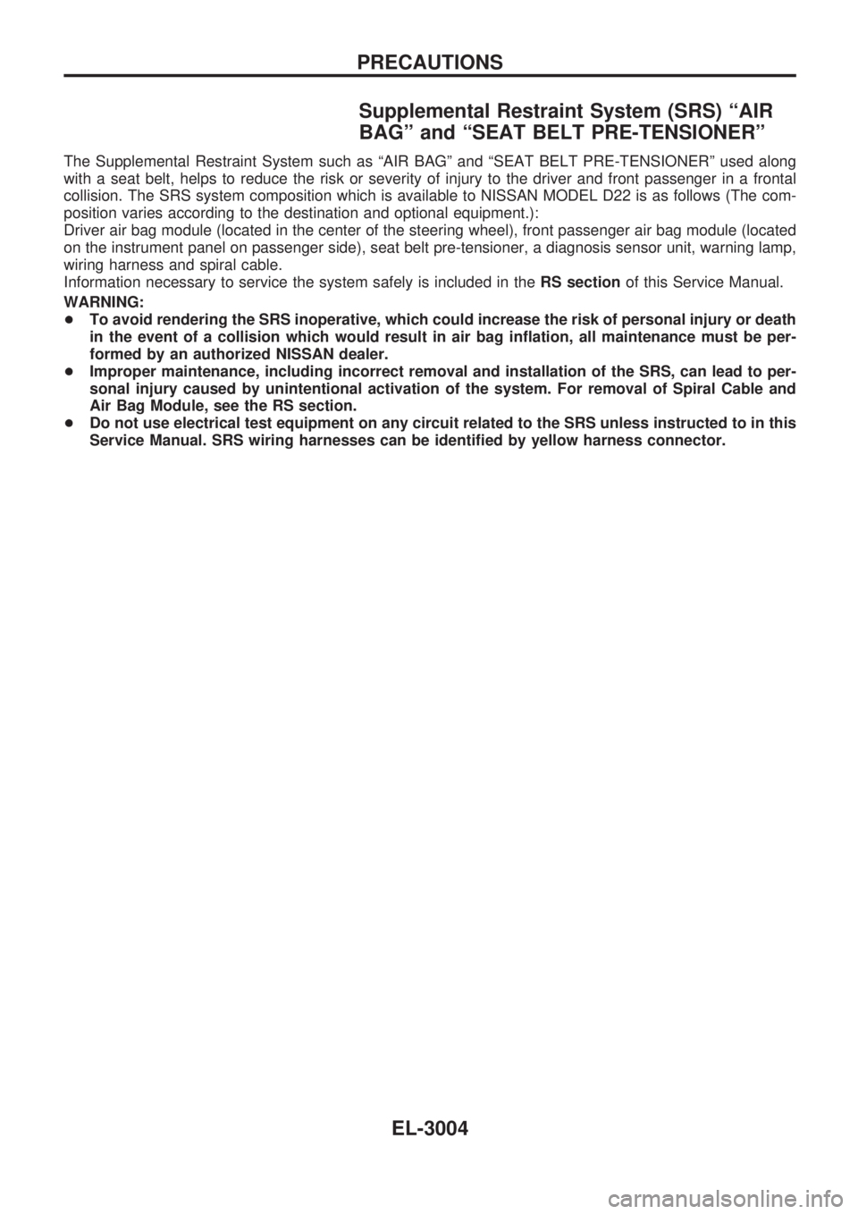
Supplemental Restraint System (SRS) ªAIR
BAGº and ªSEAT BELT PRE-TENSIONERº
The Supplemental Restraint System such as ªAIR BAGº and ªSEAT BELT PRE-TENSIONERº used along
with a seat belt, helps to reduce the risk or severity of injury to the driver and front passenger in a frontal
collision. The SRS system composition which is available to NISSAN MODEL D22 is as follows (The com-
position varies according to the destination and optional equipment.):
Driver air bag module (located in the center of the steering wheel), front passenger air bag module (located
on the instrument panel on passenger side), seat belt pre-tensioner, a diagnosis sensor unit, warning lamp,
wiring harness and spiral cable.
Information necessary to service the system safely is included in theRS sectionof this Service Manual.
WARNING:
+To avoid rendering the SRS inoperative, which could increase the risk of personal injury or death
in the event of a collision which would result in air bag inflation, all maintenance must be per-
formed by an authorized NISSAN dealer.
+Improper maintenance, including incorrect removal and installation of the SRS, can lead to per-
sonal injury caused by unintentional activation of the system. For removal of Spiral Cable and
Air Bag Module, see the RS section.
+Do not use electrical test equipment on any circuit related to the SRS unless instructed to in this
Service Manual. SRS wiring harnesses can be identified by yellow harness connector.
PRECAUTIONS
EL-3004