Page 101 of 1306
![NISSAN PICK-UP 2001 Repair Manual Monitored item [Unit]ECM
input
signalsMain
signalsDescription Remarks
AIR COND RLY
[ON/OFF]j+Indicates the air conditioner relay con-
trol condition determined by ECM
according to the input signals.
F NISSAN PICK-UP 2001 Repair Manual Monitored item [Unit]ECM
input
signalsMain
signalsDescription Remarks
AIR COND RLY
[ON/OFF]j+Indicates the air conditioner relay con-
trol condition determined by ECM
according to the input signals.
F](/manual-img/5/57372/w960_57372-100.png)
Monitored item [Unit]ECM
input
signalsMain
signalsDescription Remarks
AIR COND RLY
[ON/OFF]j+Indicates the air conditioner relay con-
trol condition determined by ECM
according to the input signals.
FUEL PUMP RLY
[ON/OFF]j+Indicates the fuel pump relay control
condition determined by ECM accord-
ing to the input signals.
HO2S1 HTR (B1)
[ON/OFF]+Indicates [ON/OFF] condition of heated
oxygen sensor 1 heater determined by
ECM according to the input signals.
HO2S2 HTR (B1)
[ON/OFF]+Indicates [ON/OFF] condition of heated
oxygen sensor 2 heater determined by
ECM according to the input signals.
VOLTAGE [V]+Voltage measured by the voltage
probe.
TRVL AFTER MIL
[km] or [Mile]+Distance traveled while MI is activated.
Frequency
[msec] or [Hz] or [%]+Pulse width, frequency or duty cycle
measured by the pulse probe.+Only ª#º is displayed if item is unable
to be measured.
+Figures with ª#ºs are temporary ones.
They are the same figures as an
actual piece of data which was just
previously measured.
NOTE:
Any monitored item that does not match the vehicle being diagnosed is deleted from the display automatically.
DATA MONITOR (SPEC) MODENEEC0034S12
Monitored item [Unit]ECM
input
signalsMain
signalsDescription Remarks
ENG SPEED [rpm]jj+Indicates the engine speed computed
from the REF signal (180É signal) of
the camshaft position sensor.
MAS A/F SE-B1 [V]jj+The signal voltage of the mass air flow
sensor specification is displayed.+When engine is running specification
range is indicated.
B/FUEL SCHDL
[msec]j+ªBase fuel scheduleº indicates the fuel
injection pulse width programmed into
ECM, prior to any learned on board
correction.+When engine is running specification
range is indicated.
A/F ALPHA-B1 [%]j+The mean value of the air-fuel ratio
feedback correction factor per cycle is
indicated.+When engine is running specification
range is indicated.
+This data also includes the data for the
air-fuel ratio learning control.
NOTE:
Any monitored item that does not match the vehicle being diagnosed is deleted from the display automatically.
ACTIVE TEST MODENEEC0034S07
TEST ITEM CONDITION JUDGEMENT CHECK ITEM (REMEDY)
FUEL INJECTION+Engine: Return to the original
trouble condition
+Change the amount of fuel injec-
tion using CONSULT-II.If trouble symptom disappears, see
CHECK ITEM.+Harness and connector
+Fuel injectors
+Heated oxygen sensor 1
ON BOARD DIAGNOSTIC SYSTEM
DESCRIPTION
KA24DE (EURO OBD)
CONSULT-II
EC-3076
Page 125 of 1306
DTC Inspection Priority ChartNEEC0039If some DTCs are displayed at the same time, perform inspections one by one based on the following prior-
ity chart.
Priority Detected items (DTC)
1+P0101, P0102, P0103 MAF sensor
+P0112, P0113, P0127 IAT sensor
+P0117, P0118 ECT sensor
+P0121, P0122, P0123 TP sensor
+P0327, P0328 KS
+P0340 CMP sensor
+P0500 VSS
+P0605 ECM
+P1706 PNP switch
2+P0031, P0032 HO2S1 heater
+P0037, P0038 HO2S2 heater
+P0132, P0133, P0134, P1143, P1144 HO2S1
+P0138, P0139, P1146, P1147 HO2S2
P0335, P1336 CKP sensor
+P0444, P0445 EVAP canister purge volume control solenoid valve
+P0510 CTP switch
3+P0171, P0172 Fuel injection system function
+P0300 - P0304 Misfire
+P0505 ISC system
+P0420 Three way catalyst function
TROUBLE DIAGNOSIS Ð GENERAL
DESCRIPTION
KA24DE (EURO OBD)
DTC Inspection Priority Chart
EC-3100
Page 143 of 1306
![NISSAN PICK-UP 2001 Repair Manual TERMI-
NAL
NO.WIRE
COLORITEM CONDITION DATA (DC Voltage)
109 W/R Injector No. 2
[Engine is running]
+Warm-up condition
+Engine speed is 2,000 rpmBATTERY VOLTAGE
(11 - 14V)
SEF205T
111 W/B Injector No. NISSAN PICK-UP 2001 Repair Manual TERMI-
NAL
NO.WIRE
COLORITEM CONDITION DATA (DC Voltage)
109 W/R Injector No. 2
[Engine is running]
+Warm-up condition
+Engine speed is 2,000 rpmBATTERY VOLTAGE
(11 - 14V)
SEF205T
111 W/B Injector No.](/manual-img/5/57372/w960_57372-142.png)
TERMI-
NAL
NO.WIRE
COLORITEM CONDITION DATA (DC Voltage)
109 W/R Injector No. 2
[Engine is running]
+Warm-up condition
+Engine speed is 2,000 rpmBATTERY VOLTAGE
(11 - 14V)
SEF205T
111 W/B Injector No. 4
116 B/P ECM ground[Engine is running]
+Idle speedEngine ground
117 W Current return[Engine is running]
+Idle speedBATTERY VOLTAGE
(11 - 14V)
119 Y/RHeated oxygen sensor
heater 1[Engine is running]
+Engine speed is below 3,600 rpm.Approximately 0.4V
[Engine is running]
+Engine speed is above 3,600 rpm.BATTERY VOLTAGE
(11 - 14V)
122 G/BHeated oxygen sensor
heater 2[Engine is running]
+Idle speed after driving for 2 minutes at 70
km/h (43 MPH) or moreApproximately 0.4V
[Ignition switch ON]
+Engine is not runningBATTERY VOLTAGE
(11 - 14V)
124 B/P ECM ground[Engine is running]
+Idle speedEngine ground
*1: Model without NATS (Nissan Anti-Theft System)
*2: Model with NATS (Nissan Anti-Theft System)
TROUBLE DIAGNOSIS Ð GENERAL
DESCRIPTION
KA24DE (EURO OBD)
ECM Terminals and Reference Value
EC-3118
Page 158 of 1306

DescriptionNEEC0136SYSTEM DESCRIPTIONNEEC0136S01
Sensor Input Signal to ECMECM func-
tionActuator
Camshaft position sensor Engine speedHeated
oxygen
sensor 1
heater con-
trolHeated oxygen sensor 1 heater
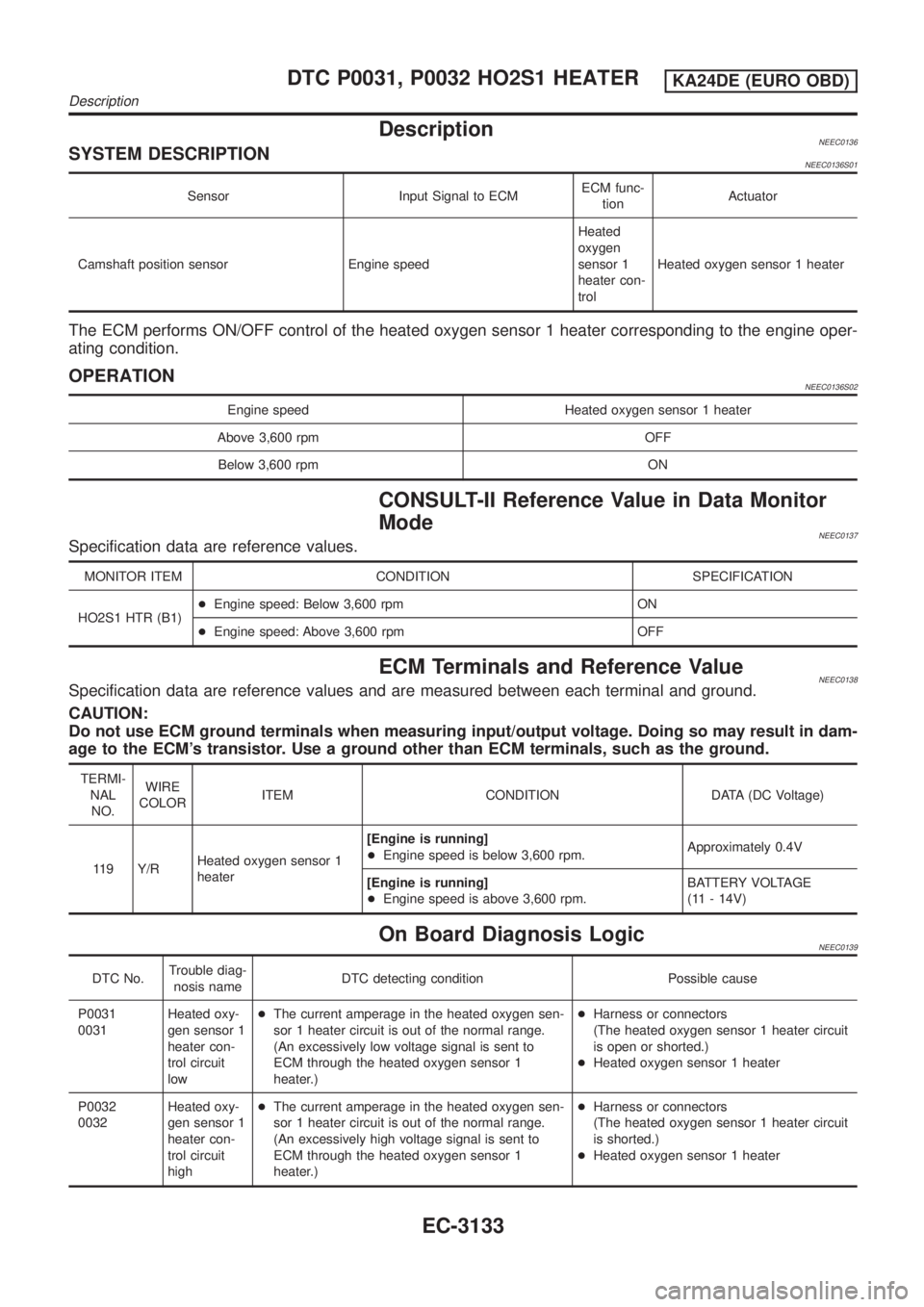
The ECM performs ON/OFF control of the heated oxygen sensor 1 heater corresponding to the engine oper-
ating condition.
OPERATIONNEEC0136S02
Engine speed Heated oxygen sensor 1 heater
Above 3,600 rpm OFF
Below 3,600 rpm ON
CONSULT-II Reference Value in Data Monitor
Mode
NEEC0137Specification data are reference values.
MONITOR ITEM CONDITION SPECIFICATION
HO2S1 HTR (B1)+Engine speed: Below 3,600 rpm ON
+Engine speed: Above 3,600 rpm OFF
ECM Terminals and Reference ValueNEEC0138Specification data are reference values and are measured between each terminal and ground.
CAUTION:
Do not use ECM ground terminals when measuring input/output voltage. Doing so may result in dam-
age to the ECM's transistor. Use a ground other than ECM terminals, such as the ground.
TERMI-
NAL
NO.WIRE
COLORITEM CONDITION DATA (DC Voltage)
119 Y/RHeated oxygen sensor 1
heater[Engine is running]
+Engine speed is below 3,600 rpm.Approximately 0.4V
[Engine is running]
+Engine speed is above 3,600 rpm.BATTERY VOLTAGE
(11 - 14V)
On Board Diagnosis LogicNEEC0139
DTC No.Trouble diag-
nosis nameDTC detecting condition Possible cause
P0031
0031Heated oxy-
gen sensor 1
heater con-
trol circuit
low+The current amperage in the heated oxygen sen-
sor 1 heater circuit is out of the normal range.
(An excessively low voltage signal is sent to
ECM through the heated oxygen sensor 1
heater.)+Harness or connectors
(The heated oxygen sensor 1 heater circuit
is open or shorted.)
+Heated oxygen sensor 1 heater
P0032
0032Heated oxy-
gen sensor 1
heater con-
trol circuit
high+The current amperage in the heated oxygen sen-
sor 1 heater circuit is out of the normal range.
(An excessively high voltage signal is sent to
ECM through the heated oxygen sensor 1
heater.)+Harness or connectors
(The heated oxygen sensor 1 heater circuit
is shorted.)
+Heated oxygen sensor 1 heater
DTC P0031, P0032 HO2S1 HEATERKA24DE (EURO OBD)
Description
EC-3133
Page 159 of 1306

DTC Confirmation ProcedureNEEC0140NOTE:
If ªDTC Confirmation Procedureº has been previously conducted,
always turn ignition switch OFF and wait at least 5 seconds before
conducting the next test.
TESTING CONDITION:
Before performing the following procedure, confirm battery
voltage is more than 11V at idle.
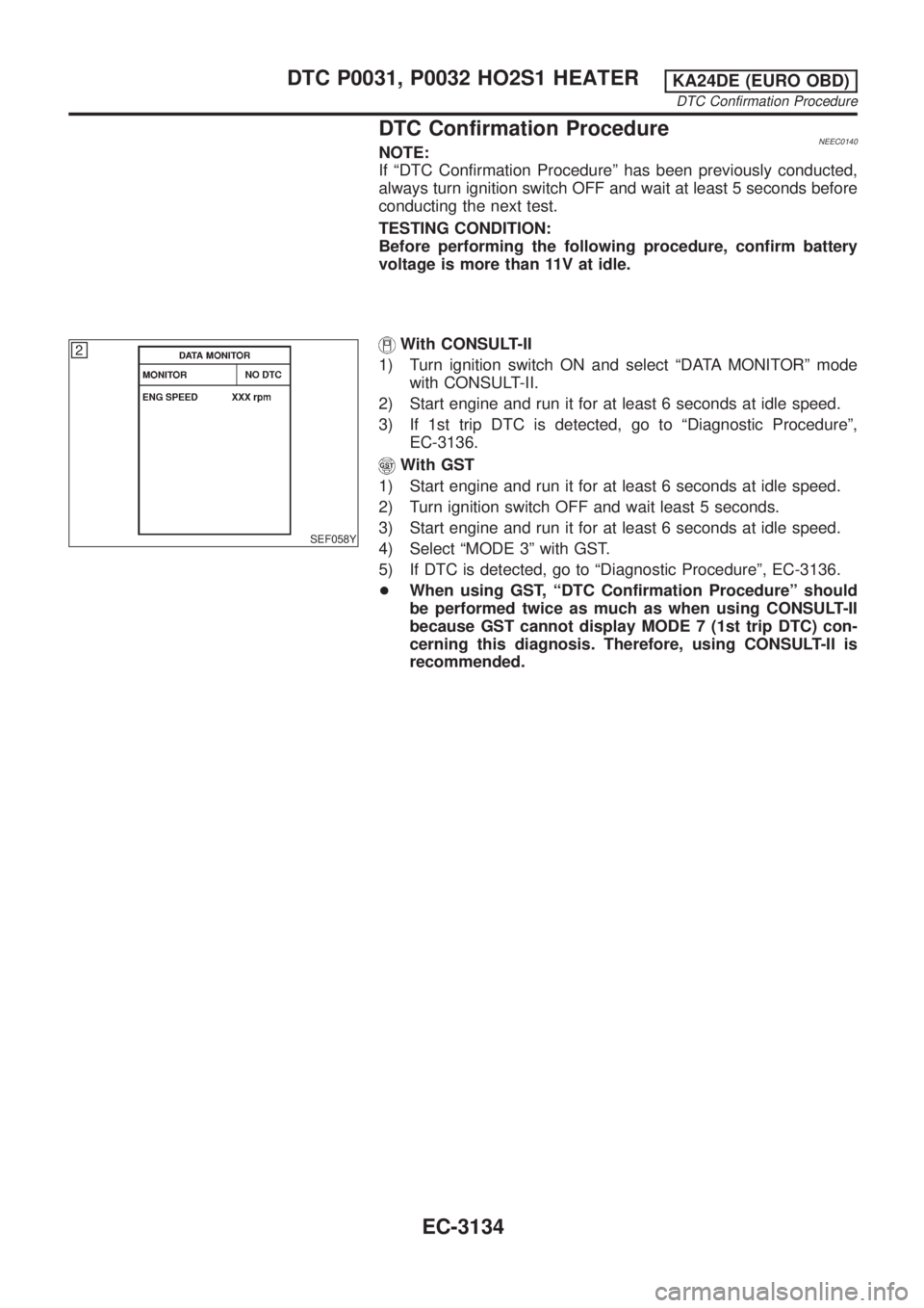
SEF058Y
With CONSULT-II
1) Turn ignition switch ON and select ªDATA MONITORº mode
with CONSULT-II.
2) Start engine and run it for at least 6 seconds at idle speed.
3) If 1st trip DTC is detected, go to ªDiagnostic Procedureº,
EC-3136.
With GST
1) Start engine and run it for at least 6 seconds at idle speed.
2) Turn ignition switch OFF and wait least 5 seconds.
3) Start engine and run it for at least 6 seconds at idle speed.
4) Select ªMODE 3º with GST.
5) If DTC is detected, go to ªDiagnostic Procedureº, EC-3136.
+When using GST, ªDTC Confirmation Procedureº should
be performed twice as much as when using CONSULT-II
because GST cannot display MODE 7 (1st trip DTC) con-
cerning this diagnosis. Therefore, using CONSULT-II is
recommended.
DTC P0031, P0032 HO2S1 HEATERKA24DE (EURO OBD)
DTC Confirmation Procedure
EC-3134
Page 160 of 1306
Wiring DiagramNEEC0141
GEC247A
DTC P0031, P0032 HO2S1 HEATERKA24DE (EURO OBD)
Wiring Diagram
EC-3135
Page 161 of 1306
Diagnostic ProcedureNEEC0142
1 CHECK POWER SUPPLY
1. Turn ignition switch OFF.
2. Disconnect heated oxygen sensor 1 harness connector.
SEF331VC
3. Turn ignition switch ON.
4. Check voltage between terminal 3 and ground with CONSULT-II or tester.
SEF732Z
Voltage: Battery voltage
OK or NG
OK©GO TO 3.
NG©GO TO 2.
2 DETECT MALFUNCTIONING PART
Check the following.
+10A fuse
+Harness for open or short between heated oxygen sensor 1 and 10A fuse
©Repair harness or connectors.
3 CHECK OUTPUT SIGNAL CIRCUIT
1. Turn ignition switch OFF.
2. Disconnect ECM harness connector.
3. Check harness continuity between heated oxygen sensor 1 terminal 1 and ECM terminal 119. Refer to the Wiring Dia-
gram.
Continuity should exist.
4. Also check harness for short to ground or short to power.
OK or NG
OK©GO TO 4.
NG©Repair open circuit or short to ground or short to power in harness or connectors.
DTC P0031, P0032 HO2S1 HEATERKA24DE (EURO OBD)
Diagnostic Procedure
EC-3136
Page 162 of 1306
4 CHECK HEATED OXYGEN SENSOR 1 HEATER
Check resistance between terminals 1 and 3.
SEF731Z
Resistance: 2.3 - 4.3Wat 25ÉC (77ÉF)
Check continuity between terminals 1 and 2, 3 and 2.
Continuity should not exist.
CAUTION:
+Discard any heated oxygen sensor which has been dropped from a height of more than 0.5 m (19.7 in) onto a
hard surface such as a concrete floor; use a new one.
+Before installing new oxygen sensor, clean exhaust system threads using Oxygen Sensor Thread Cleaner tool
J-43897-18 or J-43897-12 and approved anti-seize lubricant.
OK or NG
OK©GO TO 5.
NG©Replace heated oxygen sensor 1.
5 CHECK INTERMITTENT INCIDENT
Perform ªTROUBLE DIAGNOSIS FOR INTERMITTENT INCIDENTº, EC-3123.
©INSPECTION END
DTC P0031, P0032 HO2S1 HEATERKA24DE (EURO OBD)
Diagnostic Procedure
EC-3137