Page 339 of 1306
3 CHECK HEATED OXYGEN SENSOR 1 HEATER
Check resistance between terminals 3 and 1. Refer to wiring diagram.
Resistance: 2.3 - 4.3Wat 25ÉC (77ÉF)
Check continuity between terminals 2 and 1, 3 and 2. Refer to wiring diagram.
Continuity should not exist.
CAUTION:
Discard any heated oxygen sensor which has been dropped from a height of more than 0.5 m (19.7 in) onto a
hard surface such as a concrete floor; use a new one.
OK or NG
OK (With CONSULT-II)©GO TO 4.
OK (Without CONSULT-
II)©GO TO 5.
NG©Replace heated oxygen sensor 1.
DTC P1143 HO2S1KA24DE (EURO OBD)
Diagnostic Procedure
EC-3314
Page 343 of 1306

SEF299U
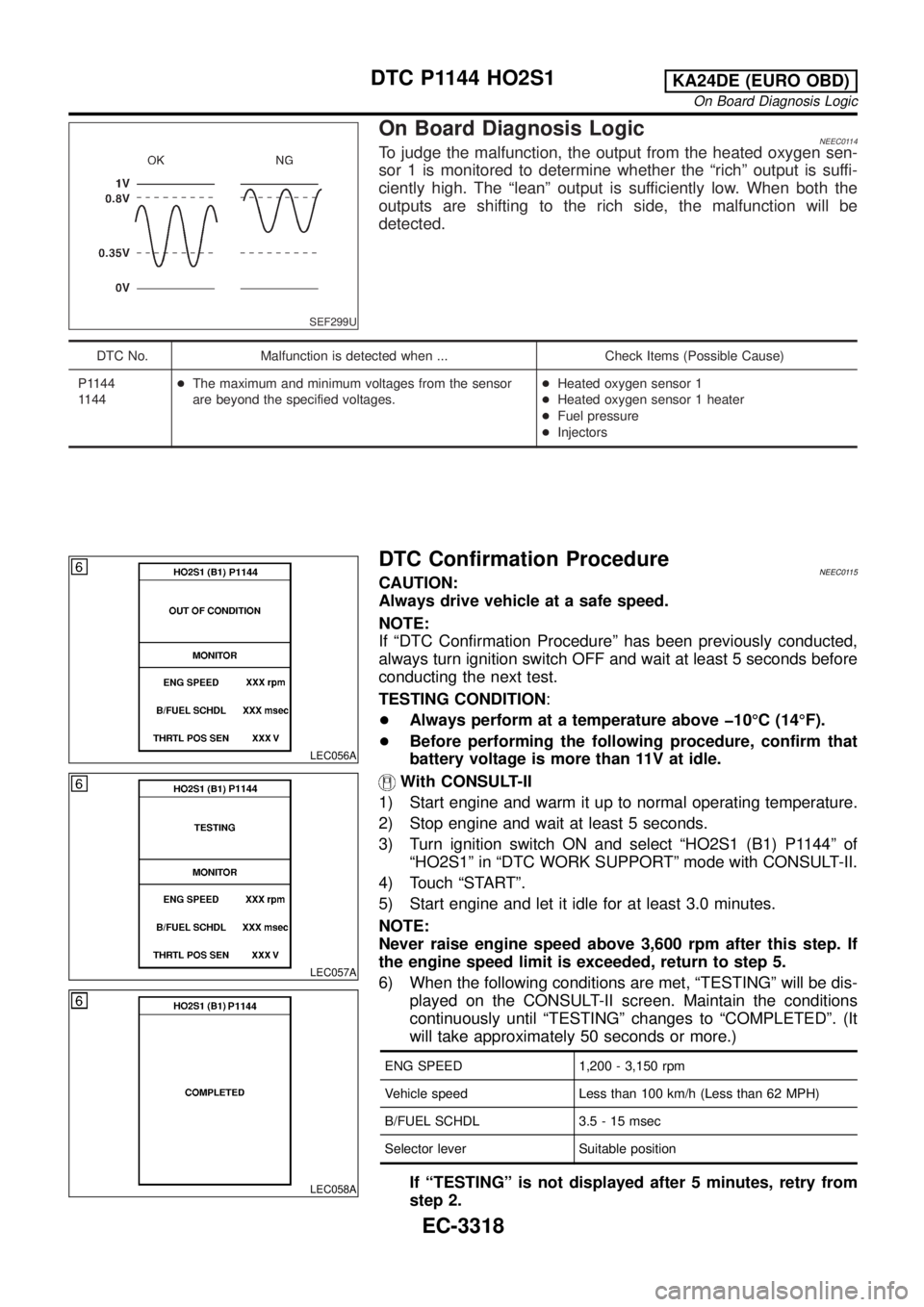
On Board Diagnosis LogicNEEC0114To judge the malfunction, the output from the heated oxygen sen-
sor 1 is monitored to determine whether the ªrichº output is suffi-
ciently high. The ªleanº output is sufficiently low. When both the
outputs are shifting to the rich side, the malfunction will be
detected.
DTC No. Malfunction is detected when ... Check Items (Possible Cause)
P1144
1144+The maximum and minimum voltages from the sensor
are beyond the specified voltages.+Heated oxygen sensor 1
+Heated oxygen sensor 1 heater
+Fuel pressure
+Injectors
LEC056A
LEC057A
LEC058A
DTC Confirmation ProcedureNEEC0115CAUTION:
Always drive vehicle at a safe speed.
NOTE:
If ªDTC Confirmation Procedureº has been previously conducted,
always turn ignition switch OFF and wait at least 5 seconds before
conducting the next test.
TESTING CONDITION:
+Always perform at a temperature above þ10ÉC (14ÉF).
+Before performing the following procedure, confirm that
battery voltage is more than 11V at idle.
With CONSULT-II
1) Start engine and warm it up to normal operating temperature.
2) Stop engine and wait at least 5 seconds.
3) Turn ignition switch ON and select ªHO2S1 (B1) P1144º of
ªHO2S1º in ªDTC WORK SUPPORTº mode with CONSULT-II.
4) Touch ªSTARTº.
5) Start engine and let it idle for at least 3.0 minutes.
NOTE:
Never raise engine speed above 3,600 rpm after this step. If
the engine speed limit is exceeded, return to step 5.
6) When the following conditions are met, ªTESTINGº will be dis-
played on the CONSULT-II screen. Maintain the conditions
continuously until ªTESTINGº changes to ªCOMPLETEDº. (It
will take approximately 50 seconds or more.)
ENG SPEED 1,200 - 3,150 rpm
Vehicle speed Less than 100 km/h (Less than 62 MPH)
B/FUEL SCHDL 3.5 - 15 msec
Selector lever Suitable position
If ªTESTINGº is not displayed after 5 minutes, retry from
step 2.
DTC P1144 HO2S1KA24DE (EURO OBD)
On Board Diagnosis Logic
EC-3318
Page 346 of 1306
4 CHECK HEATED OXYGEN SENSOR 1 HEATER
Check resistance between terminals 3 and 1. Refer to wiring diagram.
Resistance: 2.3 - 4.3Wat 25ÉC (77ÉF)
Check continuity between terminals 2 and 1, 3 and 2. Refer to wiring diagram.
Continuity should not exist.
CAUTION:
+Discard any heated oxygen sensor which has been dropped from a height of more than 0.5 m (19.7 in) onto a
hard surface such as a concrete floor; use a new one.
+Before installing new oxygen sensor, clean exhaust system threads using Oxygen Sensor Thread Cleaner tool
J-43897-18 or J-43897-12 and approved anti-seize lubricant.
OK or NG
OK (With CONSULT-II)©GO TO 5.
OK (Without CONSULT-
II)©GO TO 6.
NG©Replace heated oxygen sensor 1.
DTC P1144 HO2S1KA24DE (EURO OBD)
Diagnostic Procedure
EC-3321
Page 423 of 1306

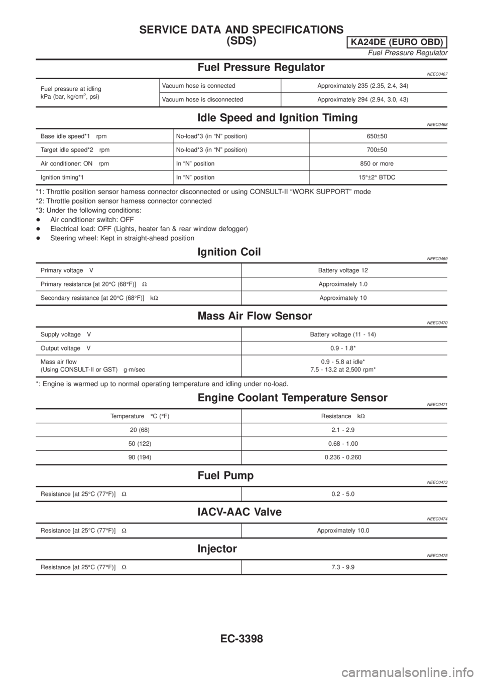
Fuel Pressure RegulatorNEEC0467
Fuel pressure at idling
kPa (bar, kg/cm2, psi)Vacuum hose is connected Approximately 235 (2.35, 2.4, 34)
Vacuum hose is disconnected Approximately 294 (2.94, 3.0, 43)
Idle Speed and Ignition TimingNEEC0468
Base idle speed*1 rpm No-load*3 (in ªNº position) 650±50
Target idle speed*2 rpm No-load*3 (in ªNº position) 700±50
Air conditioner: ON rpm In ªNº position 850 or more
Ignition timing*1 In ªNº position 15ɱ2É BTDC
*1: Throttle position sensor harness connector disconnected or using CONSULT-II ªWORK SUPPORTº mode
*2: Throttle position sensor harness connector connected
*3: Under the following conditions:
+Air conditioner switch: OFF
+Electrical load: OFF (Lights, heater fan & rear window defogger)
+Steering wheel: Kept in straight-ahead position
Ignition CoilNEEC0469
Primary voltage VBattery voltage 12
Primary resistance [at 20ÉC (68ÉF)]WApproximately 1.0
Secondary resistance [at 20ÉC (68ÉF)] kWApproximately 10
Mass Air Flow SensorNEEC0470
Supply voltage VBattery voltage (11 - 14)
Output voltage V0.9 - 1.8*
Mass air flow
(Using CONSULT-II or GST) g´m/sec0.9 - 5.8 at idle*
7.5 - 13.2 at 2,500 rpm*
*: Engine is warmed up to normal operating temperature and idling under no-load.
Engine Coolant Temperature SensorNEEC0471
Temperature ÉC (ÉF) Resistance kW
20 (68) 2.1 - 2.9
50 (122) 0.68 - 1.00
90 (194) 0.236 - 0.260
Fuel PumpNEEC0473
Resistance [at 25ÉC (77ÉF)]W0.2 - 5.0
IACV-AAC ValveNEEC0474
Resistance [at 25ÉC (77ÉF)]WApproximately 10.0
InjectorNEEC0475
Resistance [at 25ÉC (77ÉF)]W7.3 - 9.9
SERVICE DATA AND SPECIFICATIONS
(SDS)
KA24DE (EURO OBD)
Fuel Pressure Regulator
EC-3398
Page 424 of 1306
Throttle Position Sensor=NEEC0477
Throttle valve conditions Voltage (at normal operating temp., engine off, ignition switch on)
Completely closed (a)0.2 - 0.8V
Partially openBetween (a) and (b)
Completely open (b)3.5 - 4.5V
Heated Oxygen Sensor 1 HeaterNEEC0478
Resistance [at 25ÉC (77ÉF)]W2.3 - 4.3
Calculated Load ValueNEEC0479
Calculated load value %
(Using CONSULT-II or GST)
At idle9.5 - 34.0%
At 2,500 rpm13.9 - 24.9%
Intake Air Temperature SensorNEEC0480
Temperature ÉC (ÉF) Resistance kW
20 (68) 2.1 - 2.9
80 (176) 0.27 - 0.38
Heated Oxygen Sensor 2 HeaterNEEC0483
Resistance [at 25ÉC (77ÉF)]W2.3 - 4.3
Crankshaft Position Sensor (OBD)NEEC0484
Resistance [at 20ÉC (68ÉF)]W512 - 632
SERVICE DATA AND SPECIFICATIONS
(SDS)
KA24DE (EURO OBD)
Throttle Position Sensor
EC-3399
Page 444 of 1306
Spray Pattern Test
1. Check spray pattern by pumping tester handle one full stroke
per second.
NG spray pattern:
Does not inject straight and strong (B in the fig-
ure).
Fuel drips (C in the figure).
Does not inject evenly (D in the figure).
2. If the spray pattern is not correct, replace injection nozzle
assembly.
Electronic Control Fuel Injection Pump
REMOVAL AND INSTALLATION
Removal
1. Remove the parts shown below.
+Engine hood
+Engine coolant (drain)
+Engine cover
+Heater pipe under intake manifold
+Injection tubes
+Right splash cover (with undercover)
+Right front wheel
SEF434Z
JEC336D
BASIC SERVICE PROCEDUREYD25DDTi
Injection Tube and Injection Nozzle (Cont'd)
EC-3419
Page 663 of 1306

Component Description
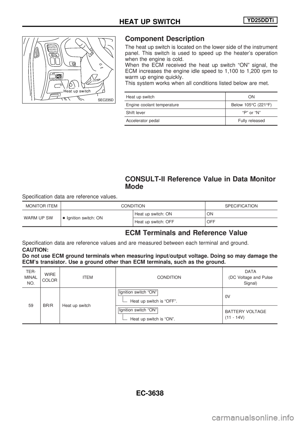
The heat up switch is located on the lower side of the instrument
panel. This switch is used to speed up the heater's operation
when the engine is cold.
When the ECM received the heat up switch ªONº signal, the
ECM increases the engine idle speed to 1,100 to 1,200 rpm to
warm up engine quickly.
This system works when all conditions listed below are met.
Heat up switch ON
Engine coolant temperature Below 105ÉC (221ÉF)
Shift lever ªPº or ªNº
Accelerator pedal Fully released
CONSULT-II Reference Value in Data Monitor
Mode
Specification data are reference values.
MONITOR ITEM CONDITION SPECIFICATION
WARM UP SW+Ignition switch: ONHeat up switch: ON ON
Heat up switch: OFF OFF
ECM Terminals and Reference Value
Specification data are reference values and are measured between each terminal and ground.
CAUTION:
Do not use ECM ground terminals when measuring input/output voltage. Doing so may damage the
ECM's transistor. Use a ground other than ECM terminals, such as the ground.
TER-
MINAL
NO.WIRE
COLORITEM CONDITIONDATA
(DC Voltage and Pulse
Signal)
59 BR/R Heat up switchIgnition switch ªONº
Heat up switch is ªOFFº.0V
Ignition switch ªONº
Heat up switch is ªONº.BATTERY VOLTAGE
(11 - 14V)
SEC235D
HEAT UP SWITCHYD25DDTi
EC-3638
Page 869 of 1306

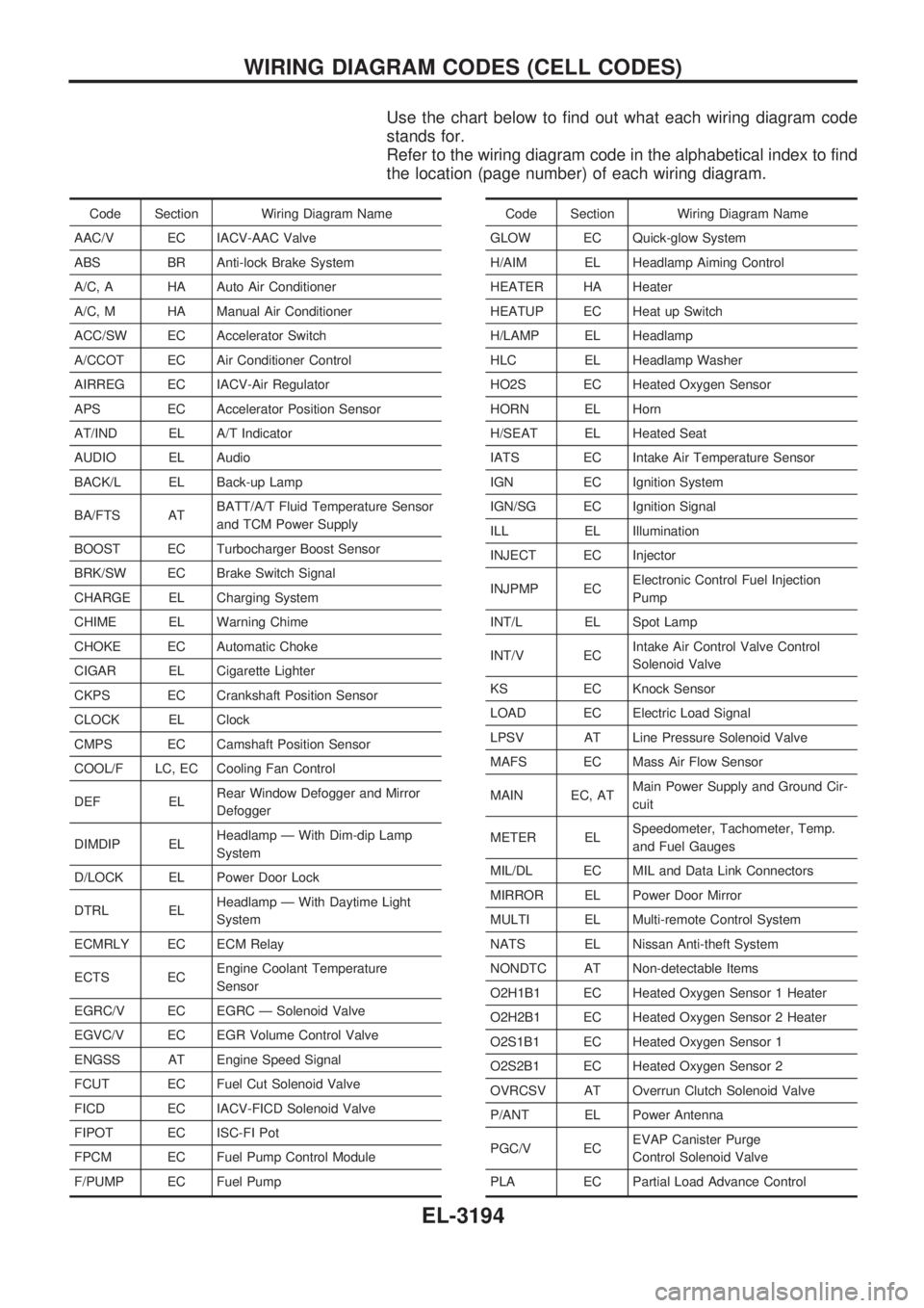
Use the chart below to find out what each wiring diagram code
stands for.
Refer to the wiring diagram code in the alphabetical index to find
the location (page number) of each wiring diagram.
Code Section Wiring Diagram Name
AAC/V EC IACV-AAC Valve
ABS BR Anti-lock Brake System
A/C, A HA Auto Air Conditioner
A/C, M HA Manual Air Conditioner
ACC/SW EC Accelerator Switch
A/CCOT EC Air Conditioner Control
AIRREG EC IACV-Air Regulator
APS EC Accelerator Position Sensor
AT/IND EL A/T Indicator
AUDIO EL Audio
BACK/L EL Back-up Lamp
BA/FTS ATBATT/A/T Fluid Temperature Sensor
and TCM Power Supply
BOOST EC Turbocharger Boost Sensor
BRK/SW EC Brake Switch Signal
CHARGE EL Charging System
CHIME EL Warning Chime
CHOKE EC Automatic Choke
CIGAR EL Cigarette Lighter
CKPS EC Crankshaft Position Sensor
CLOCK EL Clock
CMPS EC Camshaft Position Sensor
COOL/F LC, EC Cooling Fan Control
DEF ELRear Window Defogger and Mirror
Defogger
DIMDIP ELHeadlamp Ð With Dim-dip Lamp
System
D/LOCK EL Power Door Lock
DTRL ELHeadlamp Ð With Daytime Light
System
ECMRLY EC ECM Relay
ECTS ECEngine Coolant Temperature
Sensor
EGRC/V EC EGRC Ð Solenoid Valve
EGVC/V EC EGR Volume Control Valve
ENGSS AT Engine Speed Signal
FCUT EC Fuel Cut Solenoid Valve
FICD EC IACV-FICD Solenoid Valve
FIPOT EC ISC-FI Pot
FPCM EC Fuel Pump Control Module
F/PUMP EC Fuel PumpCode Section Wiring Diagram Name
GLOW EC Quick-glow System
H/AIM EL Headlamp Aiming Control
HEATER HA Heater
HEATUP EC Heat up Switch
H/LAMP EL Headlamp
HLC EL Headlamp Washer
HO2S EC Heated Oxygen Sensor
HORN EL Horn
H/SEAT EL Heated Seat
IATS EC Intake Air Temperature Sensor
IGN EC Ignition System
IGN/SG EC Ignition Signal
ILL EL Illumination
INJECT EC Injector
INJPMP ECElectronic Control Fuel Injection
Pump
INT/L EL Spot Lamp
INT/V ECIntake Air Control Valve Control
Solenoid Valve
KS EC Knock Sensor
LOAD EC Electric Load Signal
LPSV AT Line Pressure Solenoid Valve
MAFS EC Mass Air Flow Sensor
MAIN EC, ATMain Power Supply and Ground Cir-
cuit
METER ELSpeedometer, Tachometer, Temp.
and Fuel Gauges
MIL/DL EC MIL and Data Link Connectors
MIRROR EL Power Door Mirror
MULTI EL Multi-remote Control System
NATS EL Nissan Anti-theft System
NONDTC AT Non-detectable Items
O2H1B1 EC Heated Oxygen Sensor 1 Heater
O2H2B1 EC Heated Oxygen Sensor 2 Heater
O2S1B1 EC Heated Oxygen Sensor 1
O2S2B1 EC Heated Oxygen Sensor 2
OVRCSV AT Overrun Clutch Solenoid Valve
P/ANT EL Power Antenna
PGC/V ECEVAP Canister Purge
Control Solenoid Valve
PLA EC Partial Load Advance Control
WIRING DIAGRAM CODES (CELL CODES)
EL-3194