2001 NISSAN PICK-UP heater
[x] Cancel search: heaterPage 975 of 1306
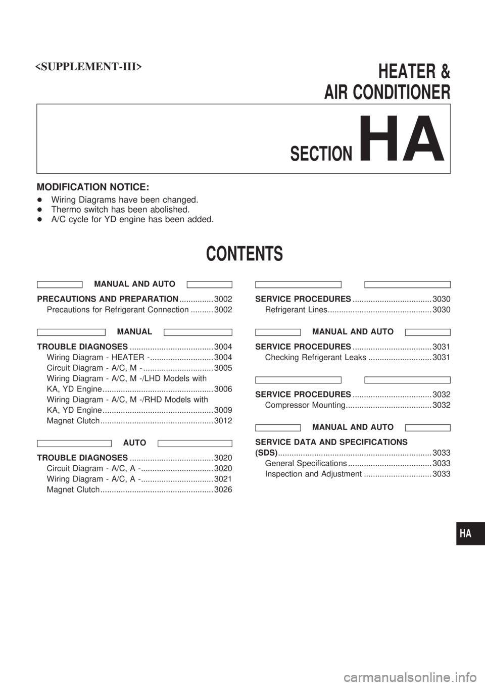
HEATER &
AIR CONDITIONER
SECTION
HA
MODIFICATION NOTICE:
+Wiring Diagrams have been changed.
+Thermo switch has been abolished.
+A/C cycle for YD engine has been added.
CONTENTS
MANUAL AND AUTO
PRECAUTIONS AND PREPARATION............... 3002
Precautions for Refrigerant Connection .......... 3002
MANUAL
TROUBLE DIAGNOSES..................................... 3004
Wiring Diagram - HEATER -............................ 3004
Circuit Diagram - A/C, M - ............................... 3005
Wiring Diagram - A/C, M -/LHD Models with
KA, YD Engine ................................................. 3006
Wiring Diagram - A/C, M -/RHD Models with
KA, YD Engine ................................................. 3009
Magnet Clutch .................................................. 3012
AUTO
TROUBLE DIAGNOSES..................................... 3020
Circuit Diagram - A/C, A -................................ 3020
Wiring Diagram - A/C, A -................................ 3021
Magnet Clutch .................................................. 3026
SERVICE PROCEDURES................................... 3030
Refrigerant Lines.............................................. 3030
MANUAL AND AUTO
SERVICE PROCEDURES................................... 3031
Checking Refrigerant Leaks ............................ 3031
SERVICE PROCEDURES................................... 3032
Compressor Mounting...................................... 3032
MANUAL AND AUTO
SERVICE DATA AND SPECIFICATIONS
(SDS).................................................................... 3033
General Specifications ..................................... 3033
Inspection and Adjustment .............................. 3033
HA
Page 978 of 1306

Wiring Diagram Ð HEATER Ð
GHA018A
TROUBLE DIAGNOSESMANUAL
HA-3004
Page 1005 of 1306
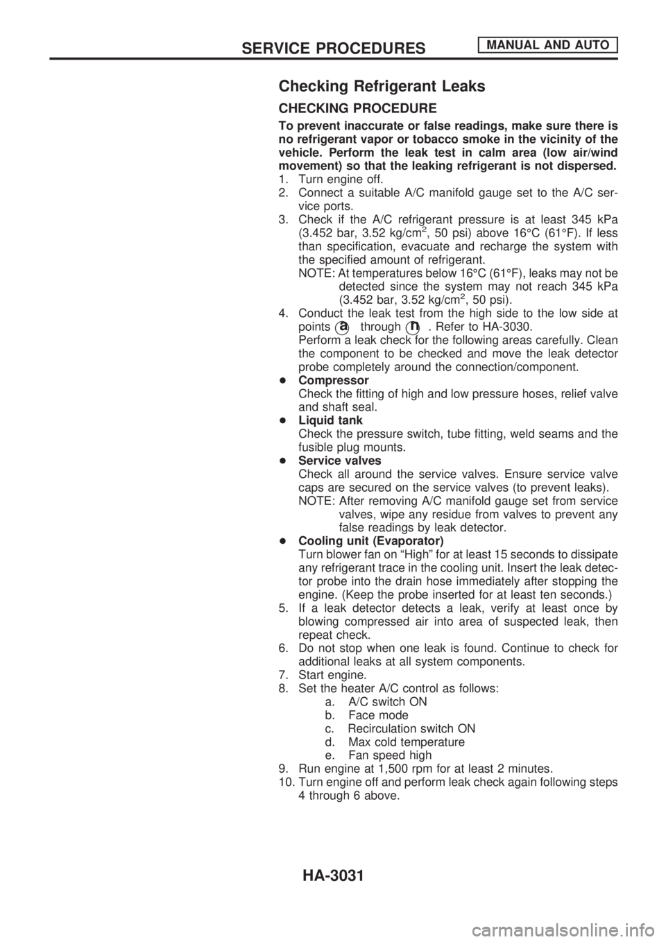
Checking Refrigerant Leaks
CHECKING PROCEDURE
To prevent inaccurate or false readings, make sure there is
no refrigerant vapor or tobacco smoke in the vicinity of the
vehicle. Perform the leak test in calm area (low air/wind
movement) so that the leaking refrigerant is not dispersed.
1. Turn engine off.
2. Connect a suitable A/C manifold gauge set to the A/C ser-
vice ports.
3. Check if the A/C refrigerant pressure is at least 345 kPa
(3.452 bar, 3.52 kg/cm
2, 50 psi) above 16ÉC (61ÉF). If less
than specification, evacuate and recharge the system with
the specified amount of refrigerant.
NOTE: At temperatures below 16ÉC (61ÉF), leaks may not be
detected since the system may not reach 345 kPa
(3.452 bar, 3.52 kg/cm
2, 50 psi).
4. Conduct the leak test from the high side to the low side at
points
jathroughjn. Refer to HA-3030.
Perform a leak check for the following areas carefully. Clean
the component to be checked and move the leak detector
probe completely around the connection/component.
+Compressor
Check the fitting of high and low pressure hoses, relief valve
and shaft seal.
+Liquid tank
Check the pressure switch, tube fitting, weld seams and the
fusible plug mounts.
+Service valves
Check all around the service valves. Ensure service valve
caps are secured on the service valves (to prevent leaks).
NOTE: After removing A/C manifold gauge set from service
valves, wipe any residue from valves to prevent any
false readings by leak detector.
+Cooling unit (Evaporator)
Turn blower fan on ªHighº for at least 15 seconds to dissipate
any refrigerant trace in the cooling unit. Insert the leak detec-
tor probe into the drain hose immediately after stopping the
engine. (Keep the probe inserted for at least ten seconds.)
5. If a leak detector detects a leak, verify at least once by
blowing compressed air into area of suspected leak, then
repeat check.
6. Do not stop when one leak is found. Continue to check for
additional leaks at all system components.
7. Start engine.
8. Set the heater A/C control as follows:
a. A/C switch ON
b. Face mode
c. Recirculation switch ON
d. Max cold temperature
e. Fan speed high
9. Run engine at 1,500 rpm for at least 2 minutes.
10. Turn engine off and perform leak check again following steps
4 through 6 above.
SERVICE PROCEDURESMANUAL AND AUTO
HA-3031
Page 1038 of 1306
10. Warm up engine, and check for sound of coolant flow while
running engine from idle up to 3,000 rpm with heater tem-
perature controller set at several positions between COOL
and HOT.
+Sound may be noticeable at heater water cock.
11. If sound is heard, bleed air from cooling system by repeat-
ing steps 4 through 7 until coolant level no longer drops
+Clean excess coolant from engine.
Ð FLUSHING COOLING SYSTEM Ð
1. Fill radiator and reservoir tank with water and reinstall radia-
tor cap.
2. Run engine and warm it up to normal operating temperature.
3. Rev engine two or three times under no-load.
4. Stop engine and wait until it cools down.
5. Drain water.
6. Repeat steps 1 through 5 until clear water begins to drain
from radiator.
Checking Cooling System
WARNING:
Never remove the radiator cap when the engine is hot; seri-
ous burns could be caused by high pressure fluid escaping
from the radiator.
Wrap a thick cloth around the cap and carefully remove it by
turning it a quarter turn to allow built-up pressure to escape
and then turn the cap all the way off.
CHECKING COOLING SYSTEM HOSES AND CLAMPS
Check hoses and clamps for improper attachment, leaks, cracks,
damage, loose connections, chafing and deterioration.
CHECKING RADIATOR
Check radiator for mud or clogging. If necessary, clean radiator
as follows.
+Be careful not to bend or damage the radiator fins.
+When radiator is cleaned without removal, remove all sur-
rounding parts such as cooling fan, radiator shroud and
horns. Then tape the harness and connectors to prevent
water from entering.
1. Apply water by hose to the back side of the radiator core
vertically downward.
2. Apply water again to all radiator core surfaces once per
minute.
3. Stop washing if any stains no longer flow out from the radia-
tor.
4. Blow air into the back side of radiator core vertically down-
ward.
+Use compressed air lower than 490 kPa (4.9 bar, 5 kg/cm
2,
71 psi) and keep distance more than 30 cm (11.8 in).
5. Blow air again into all the radiator core surfaces once per
minute until no water sprays out.
ENGINE MAINTENANCEYD25DDTi
Changing Engine Coolant (Cont'd)
MA-3016
Page 1048 of 1306
Oil Filter Bracket
REMOVAL
1. Remove oil filter. Refer to ªChanging Oil Filterº in MA section.
2. Loosen mounting bolts of oil filter bracket to drain the oil.
+Catch the oil with a pan or cloth.
3. Remove oil filter bracket.
INSTALLATION
1. Completely remove all foreign objects adhering to mounting
surfaces (cylinder block and bracket sides).
2. Install oil filter bracket with new gasket.
3. Install oil filter. Refer to ªChanging Oil Filterº in MA section.
OIL FILTER
The oil filter is an element type. Refer to ªChanging Oil Filterº in
MA section.
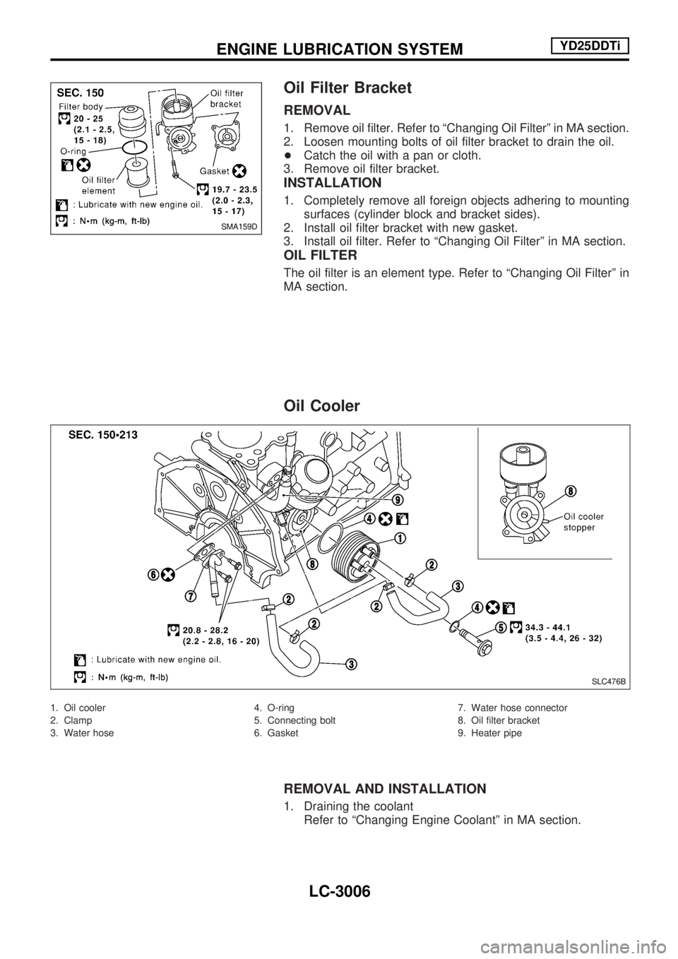
Oil Cooler
1. Oil cooler
2. Clamp
3. Water hose4. O-ring
5. Connecting bolt
6. Gasket7. Water hose connector
8. Oil filter bracket
9. Heater pipe
REMOVAL AND INSTALLATION
1. Draining the coolant
Refer to ªChanging Engine Coolantº in MA section.
SMA159D
SLC476B
ENGINE LUBRICATION SYSTEMYD25DDTi
LC-3006
Page 1063 of 1306
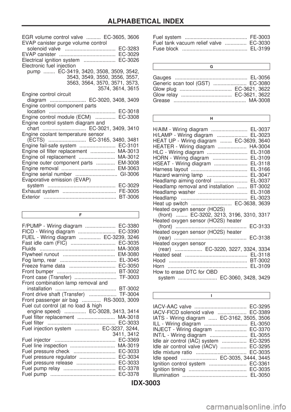
EGR volume control valve .......... EC-3605, 3606
EVAP canister purge volume control
solenoid valve ................................... EC-3283
EVAP canister ....................................... EC-3029
Electrical ignition system ...................... EC-3026
Electronic fuel injection
pump ........ EC-3419, 3420, 3508, 3509, 3542,
3543, 3549, 3550, 3556, 3557,
3563, 3564, 3570, 3571, 3573,
3574, 3614, 3615
Engine control circuit
diagram ......................... EC-3020, 3408, 3409
Engine control component parts
location .............................................. EC-3018
Engine control module (ECM) .............. EC-3308
Engine control system diagram and
chart .............................. EC-3021, 3409, 3410
Engine coolant temperature sensor
(ECTS) .......................... EC-3165, 3480, 3481
Engine fail-safe system ......................... EC-3101
Engine oil filter replacement ................. MA-3013
Engine oil replacement ......................... MA-3012
Engine outer component parts ............. EM-3008
Engine removal ..................................... EM-3063
Engine serial number ............................. GI-3006
Evaporative emission (EVAP)
system ............................................... EC-3029
Exhaust system ..................................... FE-3005
Exterior .................................................. BT-3006
F
F/PUMP - Wiring diagram ..................... EC-3380
FICD - Wiring diagram .......................... EC-3390
FUEL - Wiring diagram ............... EC-3239, 3246
Fast idle cam (FIC) ............................... EC-3035
Fluids .................................................... MA-3008
Flywheel runout .................................... EM-3080
Fog lamp, rear ....................................... EL-3045
Freeze frame data ................................ EC-3050
Front bumper ......................................... BT-3002
Front case (Transfer) ............................. TF-3003
Front combination lamp removal and
installation .......................................... BT-3002
Front drive shaft (Transfer) ................... TF-3004
Front passenger air bag ............. RS-3003, 3009
Fuel cut control (at no load & high
engine speed) ............... EC-3028, 3413, 3414
Fuel filter replacement .......................... MA-3018
Fuel filter ............................................... EC-3033
Fuel injection system ................. EC-3237, 3244,
3411, 3412
Fuel injector .......................................... EC-3369
Fuel line inspection ............................... MA-3019
Fuel pressure check ............................. EC-3033
Fuel pressure regulator ......................... EC-3034
Fuel pressure release ........................... EC-3033
Fuel pump relay .................................... EC-3378
Fuel pump ............................................. EC-3378Fuel system ........................................... FE-3003
Fuel tank vacuum relief valve ............... EC-3030
Fuse block ............................................. EL-3199
G
Gauges .................................................. EL-3056
Generic scan tool (GST) ....................... EC-3080
Glow plug .................................... EC-3621, 3622
Glow relay ................................... EC-3621, 3622
Grease .................................................. MA-3008
H
H/AIM - Wiring diagram ......................... EL-3037
H/LAMP - Wiring diagram ..................... EL-3023
HEAT UP - Wiring diagram ........ EC-3639, 3640
HEATER - Wiring diagram .................... HA-3004
HLC - Wiring diagram ............................ EL-3108
HORN - Wiring diagram ........................ EL-3109
HSEAT - Wiring diagram ....................... EL-3118
Harness layout ....................................... EL-3166
Hazard warning lamp ............................ EL-3047
Headlamp aiming control ....................... EL-3037
Headlamp removal and installation ....... BT-3002
Headlamp washer .................................. EL-3108
Headlamp .............................................. EL-3023
Heat up switch ............................ EC-3638, 3639
Heated oxygen sensor (HO2S)
(front) ........ EC-3202, 3213, 3196, 3310, 3317
Heated oxygen sensor (HO2S) heater
(front) ................................................. EC-3133
Heated oxygen sensor (HO2S) heater
(rear) .................................................. EC-3138
Heated oxygen sensor
(rear) ................... EC-3220, 3227, 3324, 3334
Heated seat ........................................... EL-3118
Hood ...................................................... BT-3002
Horn ....................................................... EL-3109
How to erase DTC for OBD
system ........................... EC-3060, 3428, 3429
I
IACV-AAC valve .................................... EC-3295
IACV-FICD solenoid valve .................... EC-3389
IATS - Wiring diagram ...... EC-3162, 3505, 3506
ILL - Wiring diagram .............................. EL-3050
INJECT - Wiring diagram ...................... EC-3370
INT/L - Wiring diagram .......................... EL-3055
Idle air control (IAC) system ................. EC-3295
Idle air control valve (IACV) .................. EC-3295
Idle mixture ratio ................................... EC-3035
Idle speed ......................... EC-3035, 3444, 3445
Ignition control system .......................... EC-3361
Ignition timing ........................................ EC-3035
Illumination ............................................. EL-3050
ALPHABETICAL INDEX
IDX-3003
Page 1305 of 1306
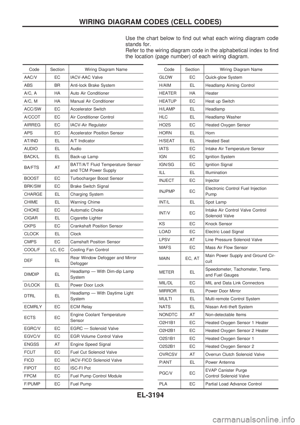
Use the chart below to find out what each wiring diagram code
stands for.
Refer to the wiring diagram code in the alphabetical index to find
the location (page number) of each wiring diagram.
Code Section Wiring Diagram Name
AAC/V EC IACV-AAC Valve
ABS BR Anti-lock Brake System
A/C, A HA Auto Air Conditioner
A/C, M HA Manual Air Conditioner
ACC/SW EC Accelerator Switch
A/CCOT EC Air Conditioner Control
AIRREG EC IACV-Air Regulator
APS EC Accelerator Position Sensor
AT/IND EL A/T Indicator
AUDIO EL Audio
BACK/L EL Back-up Lamp
BA/FTS ATBATT/A/T Fluid Temperature Sensor
and TCM Power Supply
BOOST EC Turbocharger Boost Sensor
BRK/SW EC Brake Switch Signal
CHARGE EL Charging System
CHIME EL Warning Chime
CHOKE EC Automatic Choke
CIGAR EL Cigarette Lighter
CKPS EC Crankshaft Position Sensor
CLOCK EL Clock
CMPS EC Camshaft Position Sensor
COOL/F LC, EC Cooling Fan Control
DEF ELRear Window Defogger and Mirror
Defogger
DIMDIP ELHeadlamp Ð With Dim-dip Lamp
System
D/LOCK EL Power Door Lock
DTRL ELHeadlamp Ð With Daytime Light
System
ECMRLY EC ECM Relay
ECTS ECEngine Coolant Temperature
Sensor
EGRC/V EC EGRC Ð Solenoid Valve
EGVC/V EC EGR Volume Control Valve
ENGSS AT Engine Speed Signal
FCUT EC Fuel Cut Solenoid Valve
FICD EC IACV-FICD Solenoid Valve
FIPOT EC ISC-FI Pot
FPCM EC Fuel Pump Control Module
F/PUMP EC Fuel PumpCode Section Wiring Diagram Name
GLOW EC Quick-glow System
H/AIM EL Headlamp Aiming Control
HEATER HA Heater
HEATUP EC Heat up Switch
H/LAMP EL Headlamp
HLC EL Headlamp Washer
HO2S EC Heated Oxygen Sensor
HORN EL Horn
H/SEAT EL Heated Seat
IATS EC Intake Air Temperature Sensor
IGN EC Ignition System
IGN/SG EC Ignition Signal
ILL EL Illumination
INJECT EC Injector
INJPMP ECElectronic Control Fuel Injection
Pump
INT/L EL Spot Lamp
INT/V ECIntake Air Control Valve Control
Solenoid Valve
KS EC Knock Sensor
LOAD EC Electric Load Signal
LPSV AT Line Pressure Solenoid Valve
MAFS EC Mass Air Flow Sensor
MAIN EC, ATMain Power Supply and Ground Cir-
cuit
METER ELSpeedometer, Tachometer, Temp.
and Fuel Gauges
MIL/DL EC MIL and Data Link Connectors
MIRROR EL Power Door Mirror
MULTI EL Multi-remote Control System
NATS EL Nissan Anti-theft System
NONDTC AT Non-detectable Items
O2H1B1 EC Heated Oxygen Sensor 1 Heater
O2H2B1 EC Heated Oxygen Sensor 2 Heater
O2S1B1 EC Heated Oxygen Sensor 1
O2S2B1 EC Heated Oxygen Sensor 2
OVRCSV AT Overrun Clutch Solenoid Valve
P/ANT EL Power Antenna
PGC/V ECEVAP Canister Purge
Control Solenoid Valve
PLA EC Partial Load Advance Control
WIRING DIAGRAM CODES (CELL CODES)
EL-3194