2001 NISSAN PICK-UP change wheel
[x] Cancel search: change wheelPage 574 of 1306
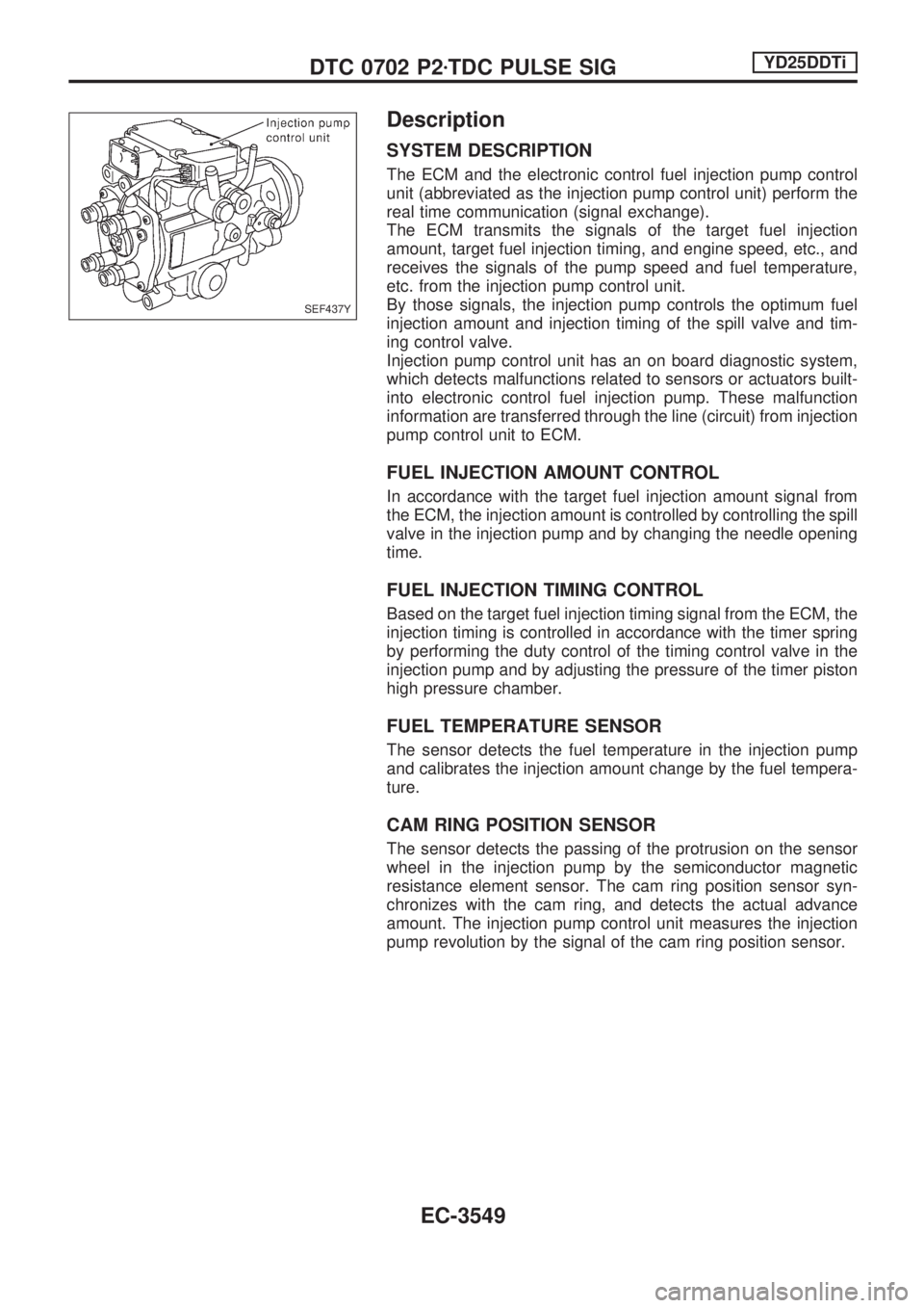
Description
SYSTEM DESCRIPTION
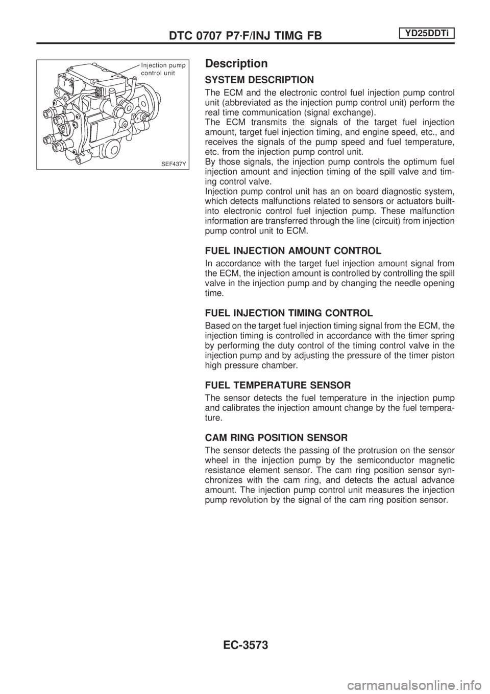
The ECM and the electronic control fuel injection pump control
unit (abbreviated as the injection pump control unit) perform the
real time communication (signal exchange).
The ECM transmits the signals of the target fuel injection
amount, target fuel injection timing, and engine speed, etc., and
receives the signals of the pump speed and fuel temperature,
etc. from the injection pump control unit.
By those signals, the injection pump controls the optimum fuel
injection amount and injection timing of the spill valve and tim-
ing control valve.
Injection pump control unit has an on board diagnostic system,
which detects malfunctions related to sensors or actuators built-
into electronic control fuel injection pump. These malfunction
information are transferred through the line (circuit) from injection
pump control unit to ECM.
FUEL INJECTION AMOUNT CONTROL
In accordance with the target fuel injection amount signal from
the ECM, the injection amount is controlled by controlling the spill
valve in the injection pump and by changing the needle opening
time.
FUEL INJECTION TIMING CONTROL
Based on the target fuel injection timing signal from the ECM, the
injection timing is controlled in accordance with the timer spring
by performing the duty control of the timing control valve in the
injection pump and by adjusting the pressure of the timer piston
high pressure chamber.
FUEL TEMPERATURE SENSOR
The sensor detects the fuel temperature in the injection pump
and calibrates the injection amount change by the fuel tempera-
ture.
CAM RING POSITION SENSOR
The sensor detects the passing of the protrusion on the sensor
wheel in the injection pump by the semiconductor magnetic
resistance element sensor. The cam ring position sensor syn-
chronizes with the cam ring, and detects the actual advance
amount. The injection pump control unit measures the injection
pump revolution by the signal of the cam ring position sensor.
SEF437Y
DTC 0702 P2zTDC PULSE SIGYD25DDTi
EC-3549
Page 581 of 1306
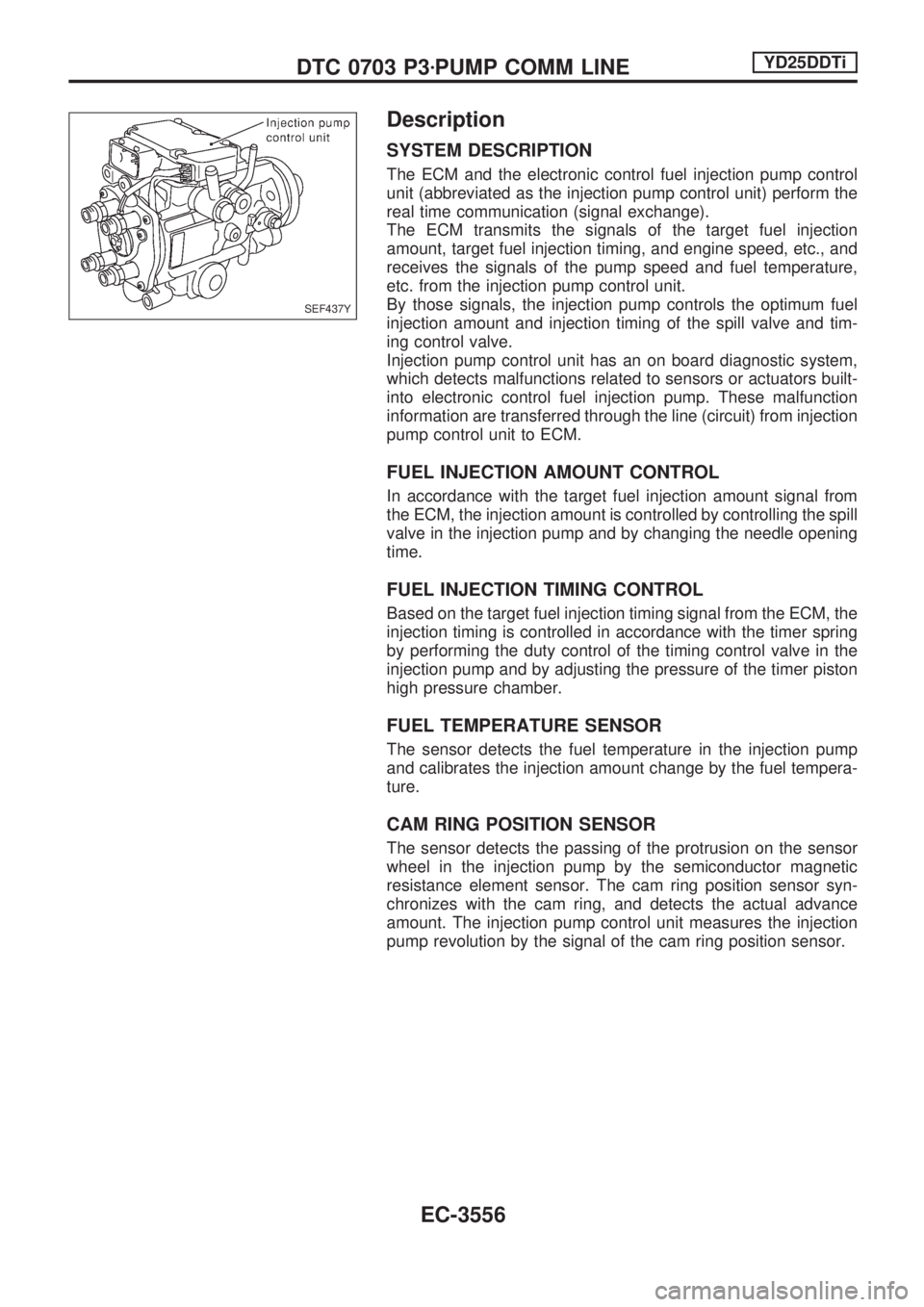
Description
SYSTEM DESCRIPTION
The ECM and the electronic control fuel injection pump control
unit (abbreviated as the injection pump control unit) perform the
real time communication (signal exchange).
The ECM transmits the signals of the target fuel injection
amount, target fuel injection timing, and engine speed, etc., and
receives the signals of the pump speed and fuel temperature,
etc. from the injection pump control unit.
By those signals, the injection pump controls the optimum fuel
injection amount and injection timing of the spill valve and tim-
ing control valve.
Injection pump control unit has an on board diagnostic system,
which detects malfunctions related to sensors or actuators built-
into electronic control fuel injection pump. These malfunction
information are transferred through the line (circuit) from injection
pump control unit to ECM.
FUEL INJECTION AMOUNT CONTROL
In accordance with the target fuel injection amount signal from
the ECM, the injection amount is controlled by controlling the spill
valve in the injection pump and by changing the needle opening
time.
FUEL INJECTION TIMING CONTROL
Based on the target fuel injection timing signal from the ECM, the
injection timing is controlled in accordance with the timer spring
by performing the duty control of the timing control valve in the
injection pump and by adjusting the pressure of the timer piston
high pressure chamber.
FUEL TEMPERATURE SENSOR
The sensor detects the fuel temperature in the injection pump
and calibrates the injection amount change by the fuel tempera-
ture.
CAM RING POSITION SENSOR
The sensor detects the passing of the protrusion on the sensor
wheel in the injection pump by the semiconductor magnetic
resistance element sensor. The cam ring position sensor syn-
chronizes with the cam ring, and detects the actual advance
amount. The injection pump control unit measures the injection
pump revolution by the signal of the cam ring position sensor.
SEF437Y
DTC 0703 P3zPUMP COMM LINEYD25DDTi
EC-3556
Page 588 of 1306
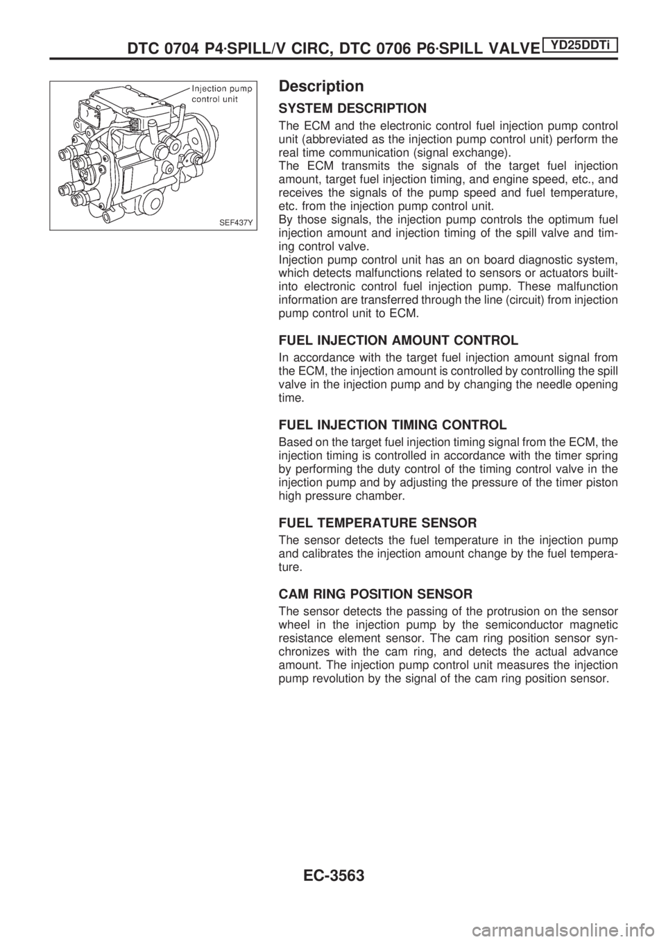
Description
SYSTEM DESCRIPTION
The ECM and the electronic control fuel injection pump control
unit (abbreviated as the injection pump control unit) perform the
real time communication (signal exchange).
The ECM transmits the signals of the target fuel injection
amount, target fuel injection timing, and engine speed, etc., and
receives the signals of the pump speed and fuel temperature,
etc. from the injection pump control unit.
By those signals, the injection pump controls the optimum fuel
injection amount and injection timing of the spill valve and tim-
ing control valve.
Injection pump control unit has an on board diagnostic system,
which detects malfunctions related to sensors or actuators built-
into electronic control fuel injection pump. These malfunction
information are transferred through the line (circuit) from injection
pump control unit to ECM.
FUEL INJECTION AMOUNT CONTROL
In accordance with the target fuel injection amount signal from
the ECM, the injection amount is controlled by controlling the spill
valve in the injection pump and by changing the needle opening
time.
FUEL INJECTION TIMING CONTROL
Based on the target fuel injection timing signal from the ECM, the
injection timing is controlled in accordance with the timer spring
by performing the duty control of the timing control valve in the
injection pump and by adjusting the pressure of the timer piston
high pressure chamber.
FUEL TEMPERATURE SENSOR
The sensor detects the fuel temperature in the injection pump
and calibrates the injection amount change by the fuel tempera-
ture.
CAM RING POSITION SENSOR
The sensor detects the passing of the protrusion on the sensor
wheel in the injection pump by the semiconductor magnetic
resistance element sensor. The cam ring position sensor syn-
chronizes with the cam ring, and detects the actual advance
amount. The injection pump control unit measures the injection
pump revolution by the signal of the cam ring position sensor.
SEF437Y
DTC 0704 P4zSPILL/V CIRC, DTC 0706 P6zSPILL VALVEYD25DDTi
EC-3563
Page 595 of 1306
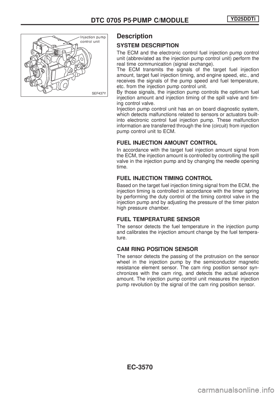
Description
SYSTEM DESCRIPTION
The ECM and the electronic control fuel injection pump control
unit (abbreviated as the injection pump control unit) perform the
real time communication (signal exchange).
The ECM transmits the signals of the target fuel injection
amount, target fuel injection timing, and engine speed, etc., and
receives the signals of the pump speed and fuel temperature,
etc. from the injection pump control unit.
By those signals, the injection pump controls the optimum fuel
injection amount and injection timing of the spill valve and tim-
ing control valve.
Injection pump control unit has an on board diagnostic system,
which detects malfunctions related to sensors or actuators built-
into electronic control fuel injection pump. These malfunction
information are transferred through the line (circuit) from injection
pump control unit to ECM.
FUEL INJECTION AMOUNT CONTROL
In accordance with the target fuel injection amount signal from
the ECM, the injection amount is controlled by controlling the spill
valve in the injection pump and by changing the needle opening
time.
FUEL INJECTION TIMING CONTROL
Based on the target fuel injection timing signal from the ECM, the
injection timing is controlled in accordance with the timer spring
by performing the duty control of the timing control valve in the
injection pump and by adjusting the pressure of the timer piston
high pressure chamber.
FUEL TEMPERATURE SENSOR
The sensor detects the fuel temperature in the injection pump
and calibrates the injection amount change by the fuel tempera-
ture.
CAM RING POSITION SENSOR
The sensor detects the passing of the protrusion on the sensor
wheel in the injection pump by the semiconductor magnetic
resistance element sensor. The cam ring position sensor syn-
chronizes with the cam ring, and detects the actual advance
amount. The injection pump control unit measures the injection
pump revolution by the signal of the cam ring position sensor.
SEF437Y
DTC 0705 P5zPUMP C/MODULEYD25DDTi
EC-3570
Page 598 of 1306
Description
SYSTEM DESCRIPTION
The ECM and the electronic control fuel injection pump control
unit (abbreviated as the injection pump control unit) perform the
real time communication (signal exchange).
The ECM transmits the signals of the target fuel injection
amount, target fuel injection timing, and engine speed, etc., and
receives the signals of the pump speed and fuel temperature,
etc. from the injection pump control unit.
By those signals, the injection pump controls the optimum fuel
injection amount and injection timing of the spill valve and tim-
ing control valve.
Injection pump control unit has an on board diagnostic system,
which detects malfunctions related to sensors or actuators built-
into electronic control fuel injection pump. These malfunction
information are transferred through the line (circuit) from injection
pump control unit to ECM.
FUEL INJECTION AMOUNT CONTROL
In accordance with the target fuel injection amount signal from
the ECM, the injection amount is controlled by controlling the spill
valve in the injection pump and by changing the needle opening
time.
FUEL INJECTION TIMING CONTROL
Based on the target fuel injection timing signal from the ECM, the
injection timing is controlled in accordance with the timer spring
by performing the duty control of the timing control valve in the
injection pump and by adjusting the pressure of the timer piston
high pressure chamber.
FUEL TEMPERATURE SENSOR
The sensor detects the fuel temperature in the injection pump
and calibrates the injection amount change by the fuel tempera-
ture.
CAM RING POSITION SENSOR
The sensor detects the passing of the protrusion on the sensor
wheel in the injection pump by the semiconductor magnetic
resistance element sensor. The cam ring position sensor syn-
chronizes with the cam ring, and detects the actual advance
amount. The injection pump control unit measures the injection
pump revolution by the signal of the cam ring position sensor.
SEF437Y
DTC 0707 P7zF/INJ TIMG FBYD25DDTi
EC-3573
Page 639 of 1306
Description
SYSTEM DESCRIPTION
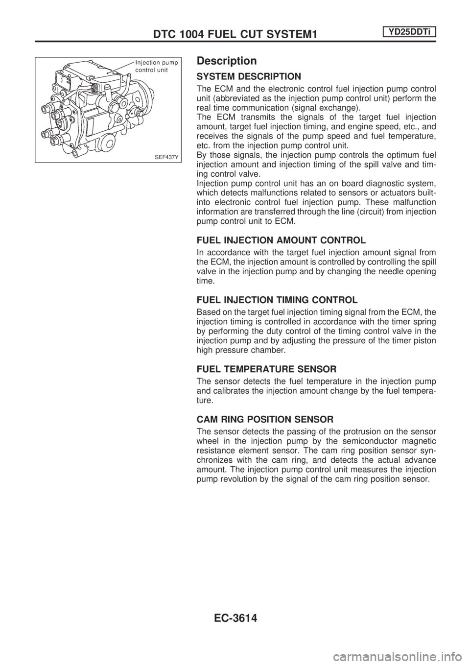
The ECM and the electronic control fuel injection pump control
unit (abbreviated as the injection pump control unit) perform the
real time communication (signal exchange).
The ECM transmits the signals of the target fuel injection
amount, target fuel injection timing, and engine speed, etc., and
receives the signals of the pump speed and fuel temperature,
etc. from the injection pump control unit.
By those signals, the injection pump controls the optimum fuel
injection amount and injection timing of the spill valve and tim-
ing control valve.
Injection pump control unit has an on board diagnostic system,
which detects malfunctions related to sensors or actuators built-
into electronic control fuel injection pump. These malfunction
information are transferred through the line (circuit) from injection
pump control unit to ECM.
FUEL INJECTION AMOUNT CONTROL
In accordance with the target fuel injection amount signal from
the ECM, the injection amount is controlled by controlling the spill
valve in the injection pump and by changing the needle opening
time.
FUEL INJECTION TIMING CONTROL
Based on the target fuel injection timing signal from the ECM, the
injection timing is controlled in accordance with the timer spring
by performing the duty control of the timing control valve in the
injection pump and by adjusting the pressure of the timer piston
high pressure chamber.
FUEL TEMPERATURE SENSOR
The sensor detects the fuel temperature in the injection pump
and calibrates the injection amount change by the fuel tempera-
ture.
CAM RING POSITION SENSOR
The sensor detects the passing of the protrusion on the sensor
wheel in the injection pump by the semiconductor magnetic
resistance element sensor. The cam ring position sensor syn-
chronizes with the cam ring, and detects the actual advance
amount. The injection pump control unit measures the injection
pump revolution by the signal of the cam ring position sensor.
SEF437Y
DTC 1004 FUEL CUT SYSTEM1YD25DDTi
EC-3614
Page 1008 of 1306
GENERAL INFORMATION
SECTION
GI
MODIFICATION NOTICE:
+YD25DDTi engine has been adopted.
+KA24E engine has been replaced with KA24DE engine.
+The appearance design has been changed.
CONTENTS
CONSULT-II CHECKING SYSTEM..................... 3002
Function and System Application .................... 3002
Nickel Metal Hydride Battery Replacement ..... 3002
Checking Equipment ........................................ 3003
CONSULT-II Data Link Connector (DLC)
Circuit ............................................................... 3003IDENTIFICATION INFORMATION...................... 3004
Model Variation ................................................ 3004
Identification Number ....................................... 3005
Wheels and Tires ............................................. 3007
Dimensions ...................................................... 3007
This modification has been included in production starting with the following vehicle identification numbers
(Chassis number):
JN1APGD22U0050001
JN1BPGD22U0030001
JN1APUD22U0030001
JN1BPUD22U0070001
JN1CPUD22U0070001
JN1ADGD22U0020001
JN1BDGD22U0030001
JN1BDUD22U0030001
JN1CDUD22U0030001
JN1CPGD22U0040001
JN1CPGD22U0740101
JN1CDUD22U0740101
JN1CPUD22U0765101
GI
Page 1064 of 1306
Injection nozzle ........................... EC-3415, 3416
Injector removal and installation ........... EC-3034
Intake air temperature
sensor ................. EC-3160, 3193, 3503, 3504
Intake manifold ..................................... EM-3008
Interior lamp ........................................... EL-3054
K
KS - Wiring diagram ............................. EC-3261
Keyless entry system - See Multi-re-
mote control system .......................... EL-3136
Knock sensor (KS) ...................... EC-3260, 3261
L
License lampEL148Parking lamp .......... EL-3039
Liquid gasket application ...................... EM-3003
Location of electrical units ..................... EL-3163
Lubricants ............................................. MA-3008
Lubrication circuit (engine) .................... LC-3003
M
M/T removal and installation ................ MT-3002
MAFS - Wiring diagram .............. EC-3146, 3154
MAIN - Wiring diagram ..... EC-3124, 3470, 3471
METER - Wiring diagram ...................... EL-3062
MIL & Data link connectors circuit ........ EC-3396
MIL/DL - Wiring diagram .. EC-3396, 3646, 3647
MIRROR - Wiring diagram .................... EL-3116
MULTI - Wiring diagram ........................ EL-3137
Main gear (Transfer) .............................. TF-3004
Mainshaft (Transfer) .............................. TF-3004
Maintenance (engine) ................. MA-3010, 3011
Malfunction indicator lamp
(MIL) ........................................ EC-3429, 3430
Manifold tightening torque (intake &
exhaust) ............................................ MA-3011
Mass air flow sensor
(MAFS) .................... DT-3143, EC-3143, 3151
Meter ...................................................... EL-3056
Misfire .................................................... EC-3251
Model variation ....................................... GI-3004
Mud guard - See Exterior ...................... BT-3006
Multi-remote control system .................. EL-3136
Multiport fuel injection (MFI) system ..... EC-3024
N
NATS (Nissan Anti-theft System) .......... EL-3143
NATS - Wiring diagram ......................... EL-3146
Neutral position switch .......................... EC-3355
O
Oil change (capacity) ............................ MA-3008
Oil cooler (engine) ................................. LC-3006
Oil pan (engine) .................................... EM-3015
Oil pressure (engine) ............................. LC-3004
Oil pump (engine) .................................. LC-3004
Oil pump regulator valve (engine) ......... LC-3005
On board diagnostic
system ........................... EC-3049, 3428, 3429
P
P/ANT - Wiring diagram ........................ EL-3115
PCV (positive crankcase
ventilation) ..................... EC-3032, 3414, 3415
PCV filter replacement ......................... MA-3010
PGC/V - Wiring diagram ....................... EC-3286
PNP/SW - Wiring diagram .................... EC-3358
POWER - Wiring diagram ..................... EL-3006
PST/SW - Wiring diagram .................... EC-3386
Park/Neutral position
switch ............................ EC-3355, 3633, 3634
Parking lamp .......................................... EL-3039
Piston assembly ................................... EM-3081
Piston pin inspection ............................ EM-3071
Piston ring inspection ........................... EM-3071
Piston to bore clearance ...................... EM-3073
Power door mirror .................................. EL-3116
Power steering oil pressure switch ....... EC-3385
Power supply routing ............................. EL-3005
Power transistor & ignition coil ............. EC-3361
Power window ....................................... EL-3120
Priming pump .............................. EC-3444, 3445
Q
Quick-glow system ...................... EC-3621, 3622
R
R/FOG - Wiring diagram ....................... EL-3045
ROOM/L - Wiring diagram ..................... EL-3054
Radiator fan - See Cooling fan ............. LC-3016
Radiator ................................................. LC-3015
Rear case (Transfer) ............................. TF-3003
Rear fog lamp ........................................ EL-3045
Rear window defogger .......................... EL-3112
Refrigerant connection precaution ........ HA-3002
Refrigerant lines .................................... HA-3030
Road wheel size ..................................... GI-3007
Room lamp ............................................ EL-3054
ALPHABETICAL INDEX
IDX-3004